forged check valve 800 lbs ( 312-313-314-318-319-358-359 ) - Saga
forged check valve 800 lbs ( 312-313-314-318-319-358-359 ) - Saga
forged check valve 800 lbs ( 312-313-314-318-319-358-359 ) - Saga

Create successful ePaper yourself
Turn your PDF publications into a flip-book with our unique Google optimized e-Paper software.
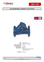
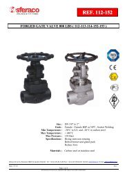
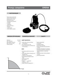
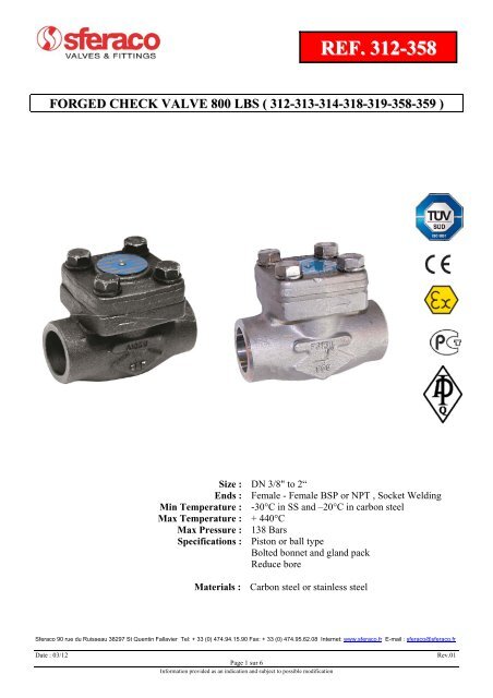
REF. <strong>312</strong>-<strong>358</strong>FORGED CHECK VALVE <strong>800</strong> LBS ( <strong>312</strong>-<strong>313</strong>-<strong>314</strong>-<strong>318</strong>-<strong>319</strong>-<strong>358</strong>-<strong>359</strong> )SPECIFICATIONS : Reduce bore Piston type (with spring) or ball type (without srping) Horizontal position only (respect the flow direction indicated by the arrow ) Bolted bonnet Forged carbon steel or stainless steel ½ stellite ( Trim 8 ) for carbon steel types Trim 10 standard inox 316 for stainless steel types <strong>800</strong> <strong>lbs</strong>USE : For common fluids Min and max Temperature Ts : - 30°C to + 440°C for stainlees steel types Ref.<strong>358</strong>/<strong>359</strong> Min and max Temperature Ts : - 20°C to + 440°C for carbon steel types Ref. <strong>312</strong>/<strong>313</strong>/<strong>314</strong>/<strong>318</strong>/<strong>319</strong> Max Pressure PN : 138 bars ( see graph )FLOW COEFFICIENT Kv ( M3 / h ) :DN 3/8“ 1/2“ 3/4“ 1“ 1“1/4 1“1/2 2“Kv ( m3/h ) 0.95 0.86 2.4 5.2 8.2 9.5 15.6PRESSURE / TEMPERATURE GRAPH :FOR CARBON STEEL TYPES ( Ref. <strong>312</strong>-<strong>313</strong>-<strong>314</strong>-<strong>318</strong>-<strong>319</strong> ) FOR STAINLESS STEEL TYPES ( Ref. <strong>358</strong>-<strong>359</strong> )Pressure ( Bar ) Pressure ( Bar )OPENING PRESSURE :Opening pressure between 300 and 600 mbarSferaco 90 rue du Ruisseau 38297 St Quentin Fallavier Tel: + 33 (0) 474.94.15.90 Fax: + 33 (0) 474.95.62.08 Internet: www.sferaco.fr E-mail : sferaco@sferaco.frDate : 03/12Page 2 sur 6Information provided as an indication and subject to possible modificationRev.01
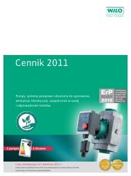
REF. <strong>312</strong>-<strong>358</strong>FORGED CHECK VALVE <strong>800</strong> LBS ( <strong>312</strong>-<strong>313</strong>-<strong>314</strong>-<strong>318</strong>-<strong>319</strong>-<strong>358</strong>-<strong>359</strong> )RANGE : Carbon steel piston type with spring Socket Welding ends Ref. <strong>312</strong> DN 10 to DN 50 Carbon steel piston type with spring threaded NPT cylindric Ref.<strong>313</strong> DN 3/8“ to DN 2“ Carbon steel piston type with spring threaded BSP cylindric Ref.<strong>314</strong> DN 3/8“ to DN 2“ Carbon steel ball type without spring Socket Welding ends Ref.<strong>318</strong> DN 10 to DN 50 Carbon steel ball type without spring threaded NPT cylindric Ref.<strong>319</strong> DN 3/8“ to DN 2“ Stainless steel ball type without spring Socket Welding ends Ref.<strong>358</strong> DN 10 to DN 50 Stainless steel ball type without spring threaded NPT cylindric Ref.<strong>359</strong> DN 3/8“ to DN 2“MATERIALS:Piston typesBall typesItem Designation Materials <strong>312</strong>/<strong>313</strong>/<strong>314</strong>/<strong>318</strong>/<strong>319</strong> Materials <strong>358</strong>/<strong>359</strong>1 Body ASTM A105 N ASTM A182 F3162 Bonnet ASTM A105 N ASTM A182 F3163 Ball ( or piston ) ASTM A276 type 410 ASTM A479 type 3164 Seat ASTM A276 TYPE 410+STELLITE GR.6’ ASTM A479 type 3165 Gasket SS 316 + graphite spiral wound SS 316 + graphite spiral wound6 Ball guide ASTM A276 type 410 ASTM A479 type 3167 Bolts ASTM A193 B7 ASTM A193 B88 Rivet Carbon steel Carbon steel9 Nameplate Aluminium Aluminium10 Spring ( for piston ) SS 302 -Sferaco 90 rue du Ruisseau 38297 St Quentin Fallavier Tel: + 33 (0) 474.94.15.90 Fax: + 33 (0) 474.95.62.08 Internet: www.sferaco.fr E-mail : sferaco@sferaco.frDate : 03/12Page 3 sur 6Information provided as an indication and subject to possible modificationRev.01
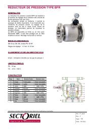
REF. <strong>312</strong>-<strong>358</strong>FORGED CHECK VALVE <strong>800</strong> LBS ( <strong>312</strong>-<strong>313</strong>-<strong>314</strong>-<strong>318</strong>-<strong>319</strong>-<strong>358</strong>-<strong>359</strong> )SIZE ( in mm ) :REF. DN 3/8" 1/2" 3/4" 1" 1"1/4 1"1/2 2"<strong>312</strong>/<strong>313</strong>/<strong>314</strong> Ø D 7 9 13 17.5 22.5 29.5 35<strong>318</strong>/<strong>319</strong> L 80 80 90 110 127 155 170<strong>358</strong>/<strong>359</strong> H 53 53 60 73 80 98 118<strong>313</strong>/<strong>314</strong>/<strong>319</strong>/<strong>359</strong> L1 13 15 18 19 20 21 21<strong>312</strong>/<strong>318</strong>/<strong>358</strong>E ( SW ) 11.1 12.7 14.5 16 17.5 19 22Ø F ( SW ) 17.6 21.72 27.05 33.78 42.54 48.64 61.11<strong>312</strong>/<strong>313</strong>/<strong>314</strong>/<strong>318</strong>/<strong>319</strong> Weight ( Kg ) 1.3 1.2 1.4 2.4 3.6 5.4 8<strong>358</strong>/<strong>359</strong> Weight ( Kg ) 1.3 1.2 1.48 2.5 3.7 5.63 8.3Sferaco 90 rue du Ruisseau 38297 St Quentin Fallavier Tel: + 33 (0) 474.94.15.90 Fax: + 33 (0) 474.95.62.08 Internet: www.sferaco.fr E-mail : sferaco@sferaco.frDate : 03/12Page 4 sur 6Information provided as an indication and subject to possible modificationRev.01
REF. <strong>312</strong>-<strong>358</strong>FORGED CHECK VALVE <strong>800</strong> LBS ( <strong>312</strong>-<strong>313</strong>-<strong>314</strong>-<strong>318</strong>-<strong>319</strong>-<strong>358</strong>-<strong>359</strong> )STANDARDS : Fabrication according to ISO 9001 : 2008 DIRECTIVE 97/23/CE : CE N° 0036Risk category III module HConception according to API 6D Tests according to API 598Approval certificate Russian Federation GOST-R Check <strong>valve</strong>s approved by the main oil industries ( certificates on request ) ATEX Group II Category 2 G/2D Zone 1 & 21 Zone 2 &22 ( optional marking )INSTALLATION POSITION :Horizontal positionADVICE : Our opinion and our advice are not guaranteed and SFERACO shall not be liable for the consequences of damages.The customer must <strong>check</strong> the right choice of the products with the real service conditions.Sferaco 90 rue du Ruisseau 38297 St Quentin Fallavier Tel: + 33 (0) 474.94.15.90 Fax: + 33 (0) 474.95.62.08 Internet: www.sferaco.fr E-mail : sferaco@sferaco.frDate : 03/12Page 5 sur 6Information provided as an indication and subject to possible modificationRev.01
REF. <strong>312</strong>-<strong>358</strong>FORGED CHECK VALVE <strong>800</strong> LBS ( <strong>312</strong>-<strong>313</strong>-<strong>314</strong>-<strong>318</strong>-<strong>319</strong>-<strong>358</strong>-<strong>359</strong> )INSTALLATION INSTRUCTIONSGENERAL GUIDELINES :Ensure that the <strong>check</strong> <strong>valve</strong>s to be used are appropriate for the conditions of the installation (type offluid,pressure and temperature).Be sure to have enough <strong>valve</strong>s to be able to isolate the sections of piping as well as the appropriateequipment for maintenance and repair.Ensure that the <strong>check</strong> <strong>valve</strong>s to be installed are of correct strenght to be able to support the capacity oftheir usage.Installation of all circuits should ensure that their function can be automatically tested on a regularbasis (at least two times a year).INSTALLATION INSTRUCTIONS :Before installing the <strong>check</strong> <strong>valve</strong>s, clean and remove any objects from the pipes (in particular bits ofsealing and metal) which could obstruct and block the <strong>check</strong> <strong>valve</strong>s.Ensure that both connecting pipes either side of the <strong>check</strong> <strong>valve</strong> (upstream and downstream) arealigned (if they’re not,the <strong>valve</strong>s may not work correctly).Make sure that the two sections of the pipe (upstream and downstream) match, the <strong>check</strong> <strong>valve</strong> unitwill not absorb any gaps. Any distortions in the pipes may affect the thightness of the connection,the working of the <strong>check</strong> <strong>valve</strong> and can even cause a rupture. To be sure, place the kit in position toensure the assembling will work.During welding operation, for S.W. types be sure to not exceed 350-400°CIf sections of piping do not have their final support in place, they should be temporarily fixed. Thisis to avoid unnecessary strain on the <strong>check</strong> <strong>valve</strong>. Fluids in the <strong>check</strong> <strong>valve</strong> must not contain solid objects ( it could damaged the seat ).If there is a direction changing or if there’s another material, it’s better to take away the <strong>check</strong> <strong>valve</strong> so thatit is outside the turbulence area ( between 3 and 5 times the ND before and after ).After a pump please refer to norm NF CR 13932 to install the <strong>check</strong> <strong>valve</strong>.Sferaco 90 rue du Ruisseau 38297 St Quentin Fallavier Tel: + 33 (0) 474.94.15.90 Fax: + 33 (0) 474.95.62.08 Internet: www.sferaco.fr E-mail : sferaco@sferaco.frDate : 03/12Page 6 sur 6Information provided as an indication and subject to possible modificationRev.01