
Create successful ePaper yourself
Turn your PDF publications into a flip-book with our unique Google optimized e-Paper software.
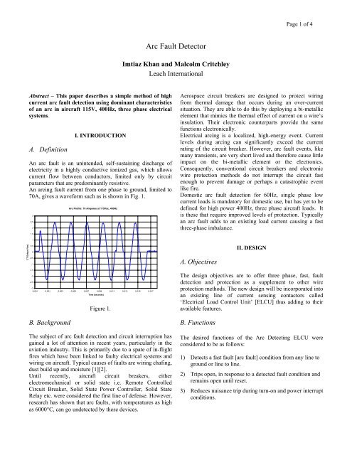
Page 1 of 4<strong>Arc</strong> <strong>Fault</strong> <strong>Detector</strong>Imtiaz Khan and Malcolm CritchleyLeach InternationalAbstract – This paper describes a simple method of highcurrent arc fault detection using dominant characteristicsof an arc in aircraft 115V, 400Hz, three phase electricalsystems.A. DefinitionI. INTRODUCTIONAn arc fault is an unintended, self-sustaining discharge ofelectricity in a highly conductive ionized gas, which allowscurrent flow between conductors, limited only by circuitparameters that are predominantly resistive.An arcing fault current from one phase to ground, limited to70A, gives a waveform such as is shown in Fig. 1.32. 521. 5<strong>Arc</strong> Profile: 70 Amperes at 115Vac, 400HzAerospace circuit breakers are designed to protect wiringfrom thermal damage that occurs during an over-currentsituation. They are able to do this by deploying a bi-metallicelement that mimics the thermal effect of current on a wire’sinsulation. Their electronic counterparts provide the samefunctions electronically.Electrical arcing is a localized, high-energy event. Currentlevels during arcing can significantly exceed the currentrating of the circuit breaker. However, arc fault events, likemany transients, are very short lived and therefore cause littleimpact on the bi-metallic element or the electronics.Consequently, conventional circuit breakers and electronicwire protection methods do not interrupt the circuit fastenough to prevent damage or perhaps a catastrophic eventlike fire.Domestic arc fault detection for 60Hz, single phase lowcurrent loads is mandatory for domestic use, but has yet to bedefined for high power 400Hz, three phase aircraft loads. Itis these that require improved levels of protection. Typicallyan arc fault adds to an existing load current causing a fastthree-phase imbalance.1CT Output (Vac)0. 50-0.5-1A. ObjectivesII. DESIGN-1.5-2-2.5-3-0.001 0.001 0.003 0.005 0.007 0.009 0.011 0.013 0.015 0.017Time (seconds)Figure 1.The design objectives are to offer three phase, fast, faultdetection and protection as a supplement to other wireprotection methods. The new design will be incorporated intoan existing line of current sensing contactors called‘Electrical Load Control Unit’ [ELCU] thus adding to theiravailable features.B. BackgroundThe subject of arc fault detection and circuit interruption hasgained a lot of attention in recent years, particularly in theaviation industry. This is primarily due to a spate of in-flightfires which have been linked to faulty electrical systems andwiring on aircraft. Typical causes of faults are wiring chafing,dust build up and moisture [1][2].Until recently, aircraft circuit breakers, eitherelectromechanical or solid state i.e. Remote ControlledCircuit Breaker, Solid State Power Controller, Solid StateRelay etc. were considered the first line of defense. However,research has shown that arc faults, with temperatures as highas 6000°C, can go undetected by these devices.B. FunctionsThe desired functions of the <strong>Arc</strong> Detecting ELCU wereconsidered to be as follows:1) Detects a fast fault [arc fault] condition from any line toground or line to line.2) Trips open, in response to a detected fault condition andremains open until reset.3) Reduces nuisance trip during turn-on and power interruptconditions.
Page 3 of 4This device is intended to limit the duration of fast occurringdamage, typically due to an arc, which is below the instanttrip and before the I 2 t trip levels as shown in Fig. 3.2) Logical comparison of signals to ensure a stable signalsource.3) Setting of level related thresholds.10000.060A ELCU Trip Curve4) Setting of time related thresholds.Instant Trip Region5) Coil disconnection when a fast fault is detected.1000.0Current(Amps rms)I 2 t Maximum Trip Limit6) Latching the fault detected condition until powerremoved.100.0Fast Trip RegionI 2 t Minimum Trip10.00.01 0.1 1 10 100 1000 10000Trip Time (seconds)Figure 3.B. Physical RequirementsThe physical requirements include form; fit and function toenable direct replacement of existing products.The available space envelope for some applications may beable to be increased but the mounting footprint is maintainedthe same as the unprotected device to provide a directreplacement.There is also a weight increase of 5% due to the addedcomponents and increase in height.C. Physical ImplementationA minimal increase in overall volume was required for themodule be fully integrated and connected into the basicassembly.A single layer PCB is used to hold all additional components.The prototype has an external physical difference of anincrease of 1.0 inches in height, which may be seen as ahousing extension in Fig.4.The circuit may be integrated within the existing envelope.D. Circuit DescriptionFig.2 is a block diagram of the model ZE ELCU contactorwith the addition of the <strong>Arc</strong> Detecting, or fast trip, modulecircuitry.Existing circuit functions are employed with the addition oflogic, filtering and integration functions.The major functions of the circuit of Fig.2 are:-1) Filtering of the incoming signals to remove noise.A. TestsFigure 4.IV. PERFORMANCEThe <strong>Arc</strong> Detecting ELCU was tested with both a manuallyoperated chaotic arc generator and an electronicallycontrolled arc generator. The electronically controlled highcurrent arc generator was designed to provide the equivalentof repeatable but programmable arc faults with timingconsistent with testing proposed for lower level single-phasearc detecting devices. The ELCU was also tested on arepresentative aircraft power panel, in a power systemlaboratory, with a representative system load.B. Test Results1) The ELCU tripped to arc faults induced using a manualarc fault generator, both in the laboratory and in the powerpanel configuration. Typical individual arc waveformssuperimposed on the load current are shown in Figs. 6 and 7.2) The ELCU tripped to varying configurations of partialsine arc fault where each fault configuration provided greaterthan the minimum setting levels within the preset timeperiods.
Page 4 of 4<strong>Arc</strong> Generator Transient Current PulseSwitch Position 1 (S1 up, S2 down, S3 up, S4 up)<strong>Arc</strong> Generator Pulse Switch Position 7Current (Amperes X 36.25)Each minor tick mark = 7.25 Amperes76543210Current (Amperes)76543210-1-1-2-0.0025 -0.002 -0.0015 -0.001 -0.0005 0 0.0005 0.001 0.0015 0.002 0.0025Time (seconds)Figure 6.-2-0.0025 -0.002 -0.0015 -0.001 -0.0005 0 0.0005 0.001 0.0015 0.002 0.0025Time (seconds)Figure 7.V. CONCLUSIONAircraft safety can be improved by preventing arc faults fromleading to catastrophic events. The <strong>Arc</strong> Detecting ELCU iscapable of opening an electrical circuit in response to thedetection of high-level arc faults. The existing performancecharacteristics are maintained.REFERENCES[1] “No-<strong>Fault</strong> Design” by Rick DeMeis, Design NewsSept.4, 2000.[2] FAA Aging Transport Non-Structural Systems Plan, July1998.ACKNOWLEDGMENTSThe work of I.Ghahramani in the design of the <strong>Arc</strong> <strong>Fault</strong>Generator, D.Sinclair in the design of the manual <strong>Arc</strong>Generator and of J.F.Bent, in the construction of theprototypes, is gratefully acknowledged.