CFRP Strand Application on Penobscot Narrows Cable Stayed Bridge
CFRP Strand Application on Penobscot Narrows Cable Stayed Bridge
CFRP Strand Application on Penobscot Narrows Cable Stayed Bridge

You also want an ePaper? Increase the reach of your titles
YUMPU automatically turns print PDFs into web optimized ePapers that Google loves.
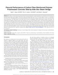
Rohleder, Jr., P.E., S.E., W. Jay Page 11FIGURE 10 – Permanent Anchor Chair with <str<strong>on</strong>g>CFRP</str<strong>on</strong>g> Load Cell and M<strong>on</strong>itoring Lead Wires.The reference strands from stays 2, 10 and 17 over the western (observatory) pyl<strong>on</strong> were replaced. Final loadslocked into the <str<strong>on</strong>g>CFRP</str<strong>on</strong>g> strands varied from 21.05 kips to 25.27 kips depending <strong>on</strong> strand locati<strong>on</strong>. Table 2 belowc<strong>on</strong>tains a full descripti<strong>on</strong> of the permanent initial loadings placed <strong>on</strong> the carb<strong>on</strong> fiber strands.Locati<strong>on</strong>Length from Jacking ChairBack Face to Pyl<strong>on</strong> Face(Length of <str<strong>on</strong>g>CFRP</str<strong>on</strong>g> <str<strong>on</strong>g>Strand</str<strong>on</strong>g>)(feet)Adjacent Steel <str<strong>on</strong>g>Strand</str<strong>on</strong>g>Force at Time of <str<strong>on</strong>g>CFRP</str<strong>on</strong>g><str<strong>on</strong>g>Strand</str<strong>on</strong>g> Stressing(kips)Actual <str<strong>on</strong>g>CFRP</str<strong>on</strong>g> <str<strong>on</strong>g>Strand</str<strong>on</strong>g>Lock-offStressing Force(kips)Stay 02 Back Span 134 25.20 25.27Stay 02 Main Span 149 22.20 22.02Stay 10 Back Span 303 22.00 21.05Stay 10 Main Span 346 21.10 21.66Stay 17 Back Span 459 22.20 21.66Stay 17 Main Span 526 21.30 20.58TABLE 2 – Carb<strong>on</strong> Fiber <str<strong>on</strong>g>Strand</str<strong>on</strong>g> Stressing Results.Other than an underestimati<strong>on</strong> of initial length needed to take out slack in the cable as it was threaded intothe stay, and the additi<strong>on</strong>al stretch of the cable within the pyl<strong>on</strong> (approximately 3 inches at all locati<strong>on</strong>s), theel<strong>on</strong>gati<strong>on</strong>s as pre-calculated were within expected tolerance of actual installati<strong>on</strong> values.