CFRP Strand Application on Penobscot Narrows Cable Stayed Bridge
CFRP Strand Application on Penobscot Narrows Cable Stayed Bridge
CFRP Strand Application on Penobscot Narrows Cable Stayed Bridge

Create successful ePaper yourself
Turn your PDF publications into a flip-book with our unique Google optimized e-Paper software.
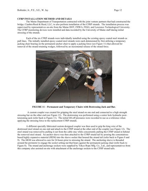
Rohleder, Jr., P.E., S.E., W. Jay Page 12<str<strong>on</strong>g>CFRP</str<strong>on</strong>g> INSTALLATION METHOD AND DETAILSThe Maine Department of Transportati<strong>on</strong> c<strong>on</strong>tracted with the joint venture partners that had c<strong>on</strong>structed thebridge, Cianbro/Reed & Reed, LLC, to also perform installati<strong>on</strong> of the <str<strong>on</strong>g>CFRP</str<strong>on</strong>g> strands. The installati<strong>on</strong> process wassupervised by representatives <strong>on</strong>-site from the Maine DOT, FHWA, FIGG, and Lawrence Technological University.The <str<strong>on</strong>g>CFRP</str<strong>on</strong>g> m<strong>on</strong>itoring devices were installed and data recorded by the University of Maine staff during initialstressing of the strands.Each of the six <str<strong>on</strong>g>CFRP</str<strong>on</strong>g> strands were individually installed using the existing epoxy coated steel strands aspull lines. The initially installed epoxy coated steel strands were each detensi<strong>on</strong>ed by first utilizing a temporaryjacking chair bearing <strong>on</strong> the permanent anchor chair to apply a jacking force (see Figure 11) that allowed forremoval of the strand retaining wedges, followed by an incremental release of the strand force.FIGURE 11 – Permanent and Temporary Chairs with Destressing Jack and Bar.A custom coupler was created for gripping the steel strand <strong>on</strong> <strong>on</strong>e end and c<strong>on</strong>nected to a high strengthstressing bar <strong>on</strong> the other end (see Figure 12). The destressing was performed using a center hole hydraulic posttensi<strong>on</strong>ingjack (refer back to Figure 11). The initial lift-off pressures were recorded to use as a reference whenapplying the stressing force to the replacement <str<strong>on</strong>g>CFRP</str<strong>on</strong>g> strands.A different specially fabricated custom designed coupler was then used to grip the king wire of thedestressed steel strand <strong>on</strong> <strong>on</strong>e end and attach to the <str<strong>on</strong>g>CFRP</str<strong>on</strong>g> strand at the other end of the coupler (see Figure 12). Thesteel strand was removed by pulling it out from the cable stay while c<strong>on</strong>currently pulling the <str<strong>on</strong>g>CFRP</str<strong>on</strong>g> strand in behindthe removed steel strand. An anchor sleeve was then attached to the <str<strong>on</strong>g>CFRP</str<strong>on</strong>g> strand tail by pouring the cementatiousbased highly expansive material (HEM) into the sleeve socket that housed the strand tail (refer back to Figure 8 and9). The HEM was allowed to cure for 24 hours prior to stressing the strand. The anchoring sleeve is threadedaround the perimeter to engage the socket setting nut that bears against the permanent jacking chair (refer back toFigure 8). The strand and anchorage sockets were supplied by Tokyo Rope Mfg. Co., Ltd., and representatives fromthis company also assisted <strong>on</strong>-site with attachment of the anchorage sockets to the <str<strong>on</strong>g>CFRP</str<strong>on</strong>g> strand tails.