Pipistrel Virus Aircraft Operating Instruction - Salsa Aviation
Pipistrel Virus Aircraft Operating Instruction - Salsa Aviation
Pipistrel Virus Aircraft Operating Instruction - Salsa Aviation

You also want an ePaper? Increase the reach of your titles
YUMPU automatically turns print PDFs into web optimized ePapers that Google loves.
AIRCRAFT OPERATING INSTRUCTIONS<strong>Pipistrel</strong> <strong>Virus</strong> 912 S-LSA GliderPIPISTREL LSA s.r.l.Via Aquileia 7534170 Gorizia, Italy, EUSERIAL NUMBER: 0359REGISTRATION: N66PV4/25/2011
AIRCRAFT OPERATING INSTRUCTIONS – VIRUS 912 S-LSA GLIDERTABLE OF CONTENTSPG1. Purpose: 52. General Information: 52.1 Read this before your first flight! 52.2 Manufacturer. 52.3 Warnings, cautions, and notes. 52.4 Revision tracking, filing, and identifying. 62.5 Online updates, service notice tracking. 62.6 Schematics of <strong>Virus</strong> 212 S-LSA Glider. 83. <strong>Aircraft</strong> and Systems Descriptions: 93.1 <strong>Operating</strong> weights and loading (occupants, baggage, fuel, ballast). 93.2 Propeller. 103.3 Fuel and fuel capacity. 103.4 Oil. 103.5 Engine. 104. <strong>Operating</strong> Limitations: 114.1 Stalling speeds at maximum takeoff weight (VS, VS0, and VS1). 114.2 Flap extended speed range (VS0 to VFE). 114.3 Maximum maneuvering speed (VA). 114.4 Never exceed speed (VNE). 114.5 Maximum aerotow speed (VT). 114.6 Maximum winch tow speed (VW). 114.7 Maximum landing gear extended operating speed (VLO). 114.8 Never exceed speed (VNE). 114.9 Crosswind and wind limitations for takeoff and landing. 114.10 Load factors. 11Page 1
AIRCRAFT OPERATING INSTRUCTIONS – VIRUS 912 S-LSA GLIDER4.11 Prohibited maneuvers. 115. Weight and Balance Information: 125.1 Installed equipment list. 125.2 Center of gravity (CG) range and determination. 136. Performance: 146.1 Gliders: 146.1.1 Crosswind and wind limitations for takeoff and landing. 146.2 Powered Gliders: 146.2.1 Takeoff distances. 146.2.2 Rate of climb. 146.2.3 Climbing speeds. 146.2.4 Maximum RPM. 146.2.5 Time limit for the use of takeoff power. 146.2.6 Fuel consumption and total usable fuel volume. 146.2.7 Crosswind and wind limitations for takeoff and landing. 146.2.8 Speeds for extracting and retracting powerplant. 147. Emergency Procedures: 157.1 Engine Failure: 157.1.1 Engine failure during takeoff run. 157.1.2 Engine failure immediately after takeoff. 157.1.3 Engine failure in flight (forced landing). 157.2 In-flight start. 167.3 Smoke and Fire: 167.3.1 Fire on the ground. 167.3.2 Fire during takeoff. 167.3.3 Fire in flight. 16Page 2
AIRCRAFT OPERATING INSTRUCTIONS – VIRUS 912 S-LSA GLIDER7.3.4 Smoke in Cockpit. 177.4 Landing emergencies: 177.4.1 Emergency landing (landing out). 177.4.2 Precautionary landing. 177.4.3 Landing with a flat tire. 177.4.4 Landing with defective landing gear. 177.4.5 Water landing (ditching). 187.5 Spin Recovery. 187.6 Other Emergencies. 187.6.1 Stall Recovery. 187.6.2 Vibration. 187.6.3 Carburetor icing. 197.6.4 Icing, pneumatic instrument failure. 197.6.5 Bird strike. 197.6.6 Structural failure. 197.6.7 Electric failure. 197.6.8 Use of GRS whole plane rescue system. 208. Normal Procedures: 208.1 Preflight check. 208.2 Powered glider normal procedures: 278.2.1 Ground engine starting. 278.2.2 Taxiing. 288.2.3 Normal takeoff. 298.2.4 Engine extraction and retraction. 318.2.5 Best rate of climb speed (VY). 318.2.6 In-flight starting of engine. 31Page 3
AIRCRAFT OPERATING INSTRUCTIONS – VIRUS 912 S-LSA GLIDER8.2.7 In-flight shutdown of engine. 318.2.8 Ground shutdown of engine. 328.3 Cruise. 328.4 Approach 328.5 Normal landing. 338.6 Information on stalls, spins, and any other useful pilot information. 349. <strong>Aircraft</strong> Ground Handling and Servicing: 389.1 Servicing fuel, oil, and coolant. 389.2 Towing and tie-down instructions. 3910. Required Placards and Markings: 4210.1 Airspeed indicator range markings. 4210.2 <strong>Operating</strong> limitations on instrument panel, if applicable. 4210.3 Passenger Warning—“This aircraft was manufactured in accordance 42with Light Sport <strong>Aircraft</strong> airworthiness standards and does not conform to standardcategory airworthiness requirements.”10.4 “NO INTENTIONAL SPINS,” if applicable. 4210.5 Empty weight. 4210.6 Maximum takeoff weight. 4210.7 Maximum and minimum weight of crew. 4310.8 Seat for solo operations of two seated gliders. 4310.9 Allowable baggage weight. 4310.10 Placards. 4411. Supplementary Information: 4511.1 Familiarization flight procedures. 4511.2 Pilot operating advisories. 4712 Maintenance Manual—Maintenance manuals containing routine, inspection, and repair maintenanceprocedures for the aircraft, engine, and propeller, are provided under separate cover.Page 4
AIRCRAFT OPERATING INSTRUCTIONS – VIRUS 912 S-LSA GLIDER1. PURPOSE. To provide a standard instruction for the safe and efficient use of this <strong>Pipistrel</strong> <strong>Aircraft</strong>. Bycombining a comprehensive instruction which describes Systems, Performance, Procedures, andLimitations, this <strong>Instruction</strong> will provide the owner/pilot with the knowledge required to safely share thepassion of flight for many years.This aircraft was built In accordance with the specifications of ASTMs F 2564, 2279, 2295, 2316, and 2483.Additionally, we have used a power plant which complies with ASTM F 2339. Every <strong>Pipistrel</strong> LSA Glider isaccompanied by an <strong>Aircraft</strong> <strong>Operating</strong> <strong>Instruction</strong> (AOI). The content and format herewith is defined byF 2564. Additions to F 2564 standards format are included wherever necessary to adequately describethe safe operation of the aircraft. All flight speeds are given in terms of calibrated airspeeds (CAS),unless otherwise noted. All specifications and limitations are determined from the specification F 2564.Capacities, Dimensions, and Performance Measures are framed in terms commonly used in the AmericanMarket. Although US temperatures are normally measured in degrees Fahrenheit, this instruction willuse degrees Centigrade, now commonly used in the US, to avoid confusion with instruments that displaytemperatures in degrees Celsius/Centigrade.2. GENERAL INFORMATION.2.1 Read this before your first flight! Every pilot must understand the capabilities andlimitations of this light sport glider. The AOI must be read thoroughly. Pay attention to the preflightand daily checks. Maintenance instructions for the aircraft are given in a separateMaintenance Manual. For maintenance of the Rotax® engine, emergency parachute system andother installed equipment refer to the original manufacturer´s manuals. Flying the <strong>Virus</strong>, like anyother motor glider, must include planning for a safe landing due to the possible loss of the enginepower at any time.This <strong>Pipistrel</strong> <strong>Virus</strong> is designed for and capable of day and night VFR flight. Because of its cruisingspeed and range, flight into vastly different weather patterns and meteorological conditions canoccur. The entry into bad weather with IFR conditions with VFR aircraft is extremely dangerous.As the owner or operator of an aircraft you are responsible for the safety of your passenger andyourself. Do not attempt to operate your <strong>Virus</strong> in any manner that would endanger the aircraft,the occupants, or persons on ground.2.2 Manufacturer.PIPISTREL LSA s.r.l.Via Aquileia 7534170 Gorizia, Italy, EU2.3 Warnings, Cautions, and Notes. WARNING!Disregarding the following instructions leads to severe deterioration of flight safety andhazardous situations, including such resulting in injury and loss of life. CAUTION!Disregarding the following instructions leads to serious deterioration of flight safety.Page 5
AIRCRAFT OPERATING INSTRUCTIONS – VIRUS 912 S-LSA GLIDER NOTE:An operating procedure, technique, etc., which is considered essential to emphasize.2.4 Revision tracking, filing, and identifying. Pages to be removed or replaced in the <strong>Aircraft</strong><strong>Operating</strong> <strong>Instruction</strong>s are determined by the Log of Effective pages located in this section. Thislog contains the page number and revision level for each page within the AOI. As revisions to theAOI occur, the revision level on the effected pages is updated. When two pages display the samepage number, the page with the latest revision shall be used in the AOI. The revision level on theLog Of Effective Pages shall also agree with the revision level of the page in question. Alternativeto removing and/or replacing individual pages, the owner can also print out a whole new manualin its current form, which is always available from www.pipistrel.eu. Revised material is markedwith a vertical double-bar that will extend the full length of deleted, new, or revised text addedto new or previously existing pages. This marker will be located adjacent to the applicable text inthe marking on the outer side of the page. The same system is in place when the header, figure,or any other element inside this AOI was revised. Next to the double-bar, there is also a numberindicative to which revision the change occurred in. A list of revisions is located in section 2.5below.2.5 Online updates, service notice tracking. To log into the Owner’s section, receive relevantupdates and information relevant to Service/Airworthiness, go to: www.pipistrel.eu and log inthe top right corner of the page with:Username: owner1Password: ab2008Index of revisionsThe table below indicated the Revisions, which were made from the original release to this date.Always check with your registration authority, <strong>Pipistrel</strong> USA (www.pipistrel-usa.com) or <strong>Pipistrel</strong>LSA s.r.l (www.pipistrel.eu) that you are familiar with the current release of the operationrelevantdocumentation, which includes this POH.Designation Reason for Revision Release date Affected pages IssuerOriginal / 25 October, 2010 /Tomazic,<strong>Pipistrel</strong> LSAs.r.l.Page 6
AIRCRAFT OPERATING INSTRUCTIONS – VIRUS 912 S-LSA GLIDERPage 7
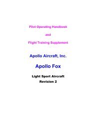
43.3 ”13.4 ”43.1 ”39.4 ”18 ’ 9.6 ”11 ‘ 0.7 ”63.4 ”46.1 ”22.4”71.7 ”9 ‘ 1.5 ”AIRCRAFT OPERATING INSTRUCTIONS – VIRUS 912 S-LSA GLIDER2.6 Schematics of <strong>Virus</strong> 912 S-LSA Glider. (dimensions in feet or inches)24.8”36.2 ”60 ”21’ 3.7”40’ 10.6”43.3”44.5”64.6”68.6”68.6”10.4”10’ 6.4”29.1”Page 8
AIRCRAFT OPERATING INSTRUCTIONS – VIRUS 912 S-LSA GLIDER3. AIRCRAFT SYSTEMS AND DESCRIPTIONS.<strong>Pipistrel</strong> <strong>Virus</strong> S-LSA Glider is intended for recreational, sport, cross-country, and training; but it is notapproved for aerobatic operation.The <strong>Virus</strong> is a single engine, carbon, Kevlar, and glass aircraft with two side-by-side seats. It is equippedwith a tricycle gear undercarriage with a steerable nose wheel and toe brakes. The fuselage is a carbonshell with carbon/Kevlar seats integrated. The wing is a mono-spar construction with a sandwich skincomposed of two layers of fiberglass with a foam core. Control surfaces are of the same construction.The aircraft is controlled by a dual push-pull control system. The ailerons and elevator are controlled bythe control sticks located between the pilot's and co-pilot’s legs. The rudder is controlled by the rudderpedals, flaps and spoilers are operated by control levers located between the pilots.3.1 <strong>Operating</strong> weights and loading SN: 359.empty weight702.5 lbs (319.3 kg)max. takeoff weight (MTOM)1210 lbs (550 kg)fuel capacity (full) 2 x 13 gal = 26 US gal (100 L)fuel capacity (usable) 24.5 US gal (93 L)max. fuel weight allowable167 lbs (76 kg)maximum useful load508 lbs (231.1 kg)minimum combined cockpit crew weight119 lbs (54 kg)maximum combined cockpit crew weight519 lbs (227.3 kg)luggage weight55 lbs (25 kg) (80 lbs (40 kg) if GRS is removed)WARNING! Should any of the above-listed values be exceeded, the others MUST be reduced in order tokeep MTOM below 1210 lbs (550 kg). Pay special attention to luggage weight as this is the only applicablePage 9
AIRCRAFT OPERATING INSTRUCTIONS – VIRUS 912 S-LSA GLIDERmass on the airframe that can cause the center of gravity to move out of range. Exceeding baggageweight limits can shift the aircraft’s balance to the point where the flight may become uncontrollable!NOTE: Weight and Balance information is found in paragraph 5 below.3.2 Propeller. The Propeller, made by <strong>Pipistrel</strong>, is a fixed pitch, auto-feathering, twobladed design, which is optimized for safe and efficient operation of your <strong>Pipistrel</strong> Touring(Self Launch) Motor Glider. See Maintenance Manual for inspection, adjustment, andservicing instructions.3.3 Fuel and fuel capacity. Automotive Unleaded per ASTM D 4814, minimum octane 89fuel may be used if it does not contain ethanol or special additives. 100LL may also be used.For questions about additives, see Rotax Operators Manual.Fuel is contained in two, extended range tanks, each with 13 gallon capacity (total 26 gallons)of which 24.5 gallons useable.Recommended fuelAlso approved fuelunleaded super, 89 octane, without ethanol or additivesleaded or AVGAS 100LL** Use of leaded or even low-lead fuels may reduce engine life and oil and oil filter changes atleast every 50 hours becomes crucial for proper care of your engine.WARNING! Use of fuel with alcohol content and/or other additives is not permitted.3.4 Oil. API SJ SAE, 10W-50. Rotax 912 engine oil capacity is 3 quarts. For suitable oil types refer to theoriginal Rotax Operator’s Manual.3.5 Engine.Engine model: ROTAX 912 UL (80 HP) mfg: Bombardier-RotaxCylinder Head Temperature (CHT) oC : Minimum / Working / 80 / 110 / 120HighestExhaust Gas Temperature (EGT) : Normal Range / Highest 650-885 / 900Max EGT difference 30Radiator water temperature range oC : lowest / highest 50 / 120Engine Oil Temp oC : minimum / normal range / highest 50 / 90-110 / 140Oil Pressure psi : minimum / maximum 14.5 / 87.0Max RPM (5 min) 5800Max Continuous power RPM 5500Ignition - Magneto Check RPM 4000Max single magneto drop RPM 300NOTE: This data is relevant for the pilot. Consult Rotax engine manual for all other engine details.Warning! Should the engine reading be outside of these parameters: do not take off; if in the air, land assoon as possible! Always be prepared to respond to an engine failure.Page 10
AIRCRAFT OPERATING INSTRUCTIONS – VIRUS 912 S-LSA GLIDER4. <strong>Operating</strong> Limitations4.1 Stall Speeds4.2 Flap extended speed range (VSO and VFE): 36 kts – 70 kts4.3 Maximum maneuvering speed (VA): 76 kts4.4 Never exceed speed (VNE): 120 kts4.5 Maximum aerotow speed (VT): N/A4.6 Maximum winch tow speed (VW): N/A4.7 Maximum landing gear extended operating speed (VLO): N/A4.8 Never exceed speed computation (VNE): 120 kts4.9 Crosswind and wind limitations for takeoff and landing: 15 kts4.10 Load factors.Maximum positive wing loading:Maximum negative wing loading:+ 4G- 2GNOTE: These values correspond to ASTM standards for LSAs. All parts have been tested to a safetypositive G factor of 1.875, meaning they were subjected to at least a load of plus 7.5 G4.11 Prohibited maneuvers. Aerobatics Fully developed spins Take off with less than 1.3 gallons of useable fuel Flight with both cabin doors removed Flight into known icing conditions Flight into IMCPage 11
AIRCRAFT OPERATING INSTRUCTIONS – VIRUS 912 S-LSA GLIDER5. WEIGHT AND BALANCE INFORMATION.5.1 Installed equipment list. Nose wheel, steerable Long Range Fuel Tanks, 26 gallons Large Instrument Panel Solid Luggage Compartment Side baggage door Ballistic Rescue System Airspeed Indicator Altimeter Dynon 180 EFIS Garmin GTX 327 Transponder Variometer LS 160 Oil Check door Auto feathering propeller Pedal mounted toe brakes pilot & copilot Fast mount engine cover screws Leather interior Tan and Dark Red Wings prepared plumbed for night lightingPage 12
AIRCRAFT OPERATING INSTRUCTIONS – VIRUS 912 S-LSA GLIDER5.2 Center of gravity (CG) range and determination.46”55 lbsmaxN66PVa = 40.15”<strong>Virus</strong> 912 S-LSA SN:0359c = 60”Wfr = 107.2 lbsWm = 595.3 lbsEmpty WeightWtot = 702.5 lbsDatumleading edge of wing at rootMAC 35.75 inches Length of the Line which represents the position of the wing's average (aerodynamically) cordMAC offset 1.1 inches Forward most point of the MAC begins 1.1 inch aft of the leading edge of the wing at the rootMAC fwd CG 20% design limitMAC aft CG 38% design limitFwd CG limit 8.3 inches Calculated: (20% * 35.75 + 1.1)Aft CG limit 14.7 inches Calculated: (38% * 35.75 + 1.1)a 40.15 inches Horizontal distance from center of nosewheel to leading edge of wingc 60 inches Horizontal distance from center of nosewheel to line thru center of main gearFuel arm 4 inches Fuel wt is slightly forward of the CG range, therefore full fuel results in a forward CGCrew arm 11.5 inches This arm puts the pilot and passenger on center of the CG range, so minimum crew wt results in most extreme CGsEmpty wt (EW) 702.5 lbs Weighed at Factory - fully configuredEmpty wt CG 10.7 inches Calculated: (Wt main gear / Wt main + nose )* c - a (595 / 702) * 60 - 40.15Min pilot wt 119 lbs Limited by Design - but I am not sure whyMax Crew wt (P) 500 lbs (MTOW limited - with min fuel on board)Full Fuel wt (F) 167 lbs Maximum fuel weight - 26 gal AVGAS (mogas weighs slightly less)Max Baggage (B) 55 lbs Limited by DesignerBaggage Arm 46 inches Assumes a distributed load throughout the compartmentMTOW 1210 lbs Limited by DesignMax Fuel Payload 341 lbs Maximum combined weight of passengers and baggage if full fuel is carriedCG X inches Measured from leading edge of wing at root - must be between 8.3" and 14.7"CG Formula:X =(EW*10.7) +(P*11.5) +(F*4)+(B*46)(EW + P + F + B)Forwardmost CG = 9.66 Inches Computed with light pilot, full fuel, and no baggage(there is no way to load the <strong>Virus</strong> with CG too far forward)Rearmost CG = 13.02 Inches Computed with light pilot, no fuel, and 55 lbs of baggage(even with up to 100 lbs of baggage, the CG will remain within range)EW = empty weightP = pilot & co-pilot weightF = weight of fuel on boardB = weight of baggageX = CG in inches aft of datumCG Range ( 8.3” < X < 14.7” )Page 13
AIRCRAFT OPERATING INSTRUCTIONS – VIRUS 912 S-LSA GLIDER6. PERFORMANCE.6.1 Gliders. This <strong>Virus</strong> S-LSA 912 is designed with the ability to sustain flight using lift fromnatural sources, i.e., thermals, ridge, and wave lift; therefore, it is a Glider.6.2 Powered gliders. Power can be categorized as sustainment requiring winch or towlaunch, and Self-Launch which can include touring motor gliders that provide efficient crosscountry cruise as well as efficient thermal, ridge or wave soaring. The <strong>Virus</strong> S-LSA falls intothis latter category.6.2.1 Takeoff/Landing distances in feet: ground roll over 50’ obsTake-off Grass 600’ 925’Take-off Paved 500’ 825’Landing Grass 500’ 885’Landing Paved 500’ 885’6.2.2 Rate of climb: 1080 fpm at Sea Level, MTOW and V Y6.2.3 Climbing speeds: V Y = 70 kts; V X = 52 kts6.2.4 Maximum RPM:5800 rpm for not longer than 5 minutes5800 rpm takeoff power (5 min max)5500 maximum continuous power5000 75% cruise power setting6.2.5 Time limit for the use of takeoff power: 5 minutes maximum as long as allengine temperature and pressure readings stay in the green.6.2.6 Fuel consumption and total usable fuel volume.3.3 gph at 75% cruise power setting24.5 gallons usable fuel6.2.7 Crosswind and wind limitations for takeoff and landing. Maximum allowedcrosswind speed on takeoff and landing with flaps is 15 kts. The runwaylength required is increased by 10 % for every 5 kts of crosswind component.Even if crosswind component is below 15 kts, discontinue flight shouldsurface winds be gusty or exceed 25 kts.6.2.8 Speeds for extracting and retracting powerplant. N/APage 14
AIRCRAFT OPERATING INSTRUCTIONS – VIRUS 912 S-LSA GLIDER7. EMERGENCY PROCEDURES.7.1 Engine failure7.1.1 Engine failure during take-off run.1. Apply Brakes2. Pull Throttle to Idle3. Ignition off7.1.2 Engine failure immediately after take-off.1. Fly the aircraft2. Lower nose to maintain best L/D 59 kts3. Under 100’ AGL, land straight ahead using airbrakeas required to select safest touchdown point4. 100’-200’ AGL, consider up to 90 degree turn to best landing site.If in doubt, choose the best off field area to your front. Useairbrake as required to pinpoint your touchdown location.5. Over 200’ AGL, turn into the direction of crosswindcomponent using 45 degree bank. Use airbrake once youhave the field made. Use radio to announce intentions.6. Fuel Off7. Ignition Off8. Master Off9. Land avoiding obstacles10. If terrain and obstacles cannot be avoided. DeployEmergency Rescue Chute.7.1.3 Engine failure in flight (Forced landing)1. Fly the aircraft2. Establish best L/D 59 kts3. Determine if you have enough altitude to glide to nearestairfield. If yes, consider effects of winds. If no, choosebest alternative landing site.4. Establish heading toward landing site.5. Attempt re-start.6. Make radio call to inform any other aircraft in the area.7. Use airbrake as required to touch down on chosen landingsite.8. Fuel valves Off9. Ignition Off10. Master Off11. Land avoiding obstacles12. If terrain and obstacles cannot be avoided. DeployEmergency Rescue Chute, over an open area if possible.Page 15
AIRCRAFT OPERATING INSTRUCTIONS – VIRUS 912 S-LSA GLIDER7.2 In-Flight start.1. Maintain airspeed at or below 50 kts2. Check altitude, and determine landing site if restart should fail3. Master on4. Fuel on5. Choke as needed6. Throttle closed7. Avionics Off8. Fuel pump on9. Ignition on10. Start engine11. Fuel pump off7.3 Smoke and fire.7.3.1 Fire on ground.1. Fuel valves OFF2. Throttle full open3. Master OFF4. Magnetos OFF5. Disconnect the battery from the circuit (pull battery disc. ring on the switchcolumn) 3b. Keep avionics ON and master ON as required, on approach set bothOFF.6. Perform emergency landing out procedure.7. Abandon aircraft8. Extinguish if possible or call fire department7.3.2 Fire during take-off1. Fuel valves OFF2. Throttle full open3. Master OFF4. Magnetos OFF5. Maintain 52-59 kts6. Set ventilation for adequate breathing. Keep in mind that oxygen intensifies fire.7. Perform side-slip (crab) maneuver in direction opposite the fire.8. Ignition OFF9. Land and brake10. Abandon aircraft11. Extinguish if possible or call fire department7.3.3 Fire in Flight.1. Fuel valves OFF2. Throttle full open3. Master OFF4. Magnetos OFF5. Maintain 52-59 kts6. Set ventilation for adequate breathing. Keep in mind that oxygen intensifies fire.7. Perform side-slip (crab) maneuver in direction opposite the fire.8. Ignition OFFPage 16
AIRCRAFT OPERATING INSTRUCTIONS – VIRUS 912 S-LSA GLIDER9. Land and brake10. Abandon aircraft11. Extinguish if possible or call fire department7.3.4 Smoke in Cockpit. Smoke in cockpit is usually a consequence of electrical wiringmalfunction. As it is most likely caused by a short circuit, the pilot must react as follows:1. Master switch to I (key in central position). This enables unobstructed engineoperation while at the same time disconnects all other electrical devices from thecircuit. Verify that the 12 V and optional Pitot heat are OFF as well.2. Disconnect the battery from the circuit (pull battery disconnection ring on theinstrument panel’s switch column).3. Land as soon as possible.WARNING! In case you have trouble breathing or the visibility out of the cockpit hasdegraded severely due to the smoke, open the cabin door and leave it hanging freely.Flying with the door open, do not, under any circumstances exceed 60 kts (110 km/h).7.4 Landing emergencies.7.4.1 Emergency landing (landing out).1. Select airfield if possible, if not, choose the most open area within range.2. If hazardous terrain or weather should preclude safe landing options/locations, planfor use of GRS rescue system (see 7.6.8 below)3. Shut both fuel valves.4. Master switch OFF.5. Use air brake to descend to landing point without gaining airspeed6. Approach and land with extreme caution, maintaining normal final approachairspeed.7. After having landed, leave the aircraft immediately and use cell phone to requestassistance.WARNING! The landing off airport maneuver MUST be performed in accordance with allnormal flight parameters/procedures.7.4.2 Precautionary landing. Landing under power at a field of your choice is alwayspreferable to an Emergency landing. Some reasons to consider a precautionary landing:1. Engine temp or pressure parameters out of range2. Low fuel3. Engine running rough4. Winds or weather5. Pilot illness or fatigue6. You hear strange noises (or even strange voices)7. You are lost7.4.3 Landing with a flat tire.7.4.4 Landing with defective landing gear.Page 17
AIRCRAFT OPERATING INSTRUCTIONS – VIRUS 912 S-LSA GLIDER7.4.5 Water landing (ditching). Should you be forced to land in a body of water, use thesame emergency procedure as above for the “Emergency landing / Landing out” case. Inaddition, make sure to open both doors fully before hitting the water, disconnect thebattery from the circuit (pull ring on electrical panel). Touch the water with the slowestpossible speed, if possible in a nose-high flare attitude.7.5 Spin recovery. <strong>Virus</strong> 912 LSA is constructed in such manner that it is difficult to beflown into a spin, and then, only at aft center of gravity loading. However, once spinning,either intentionally or unintentionally, react as follows:1. Set throttle to idle (lever in full back position).2. Apply full rudder deflection in the direction opposite the spin.3. Lower the nose towards the ground to build speed (stick forward).4. As the aircraft stops spinning neutralize rudder deflection.5. Slowly pull up and regain horizontal flight.NOTE: <strong>Virus</strong> 912 LSA tends to reestablish normal flight by itself usually after having spunfor a mere 45°-90°.WARNING! Keep the control stick centered along its lateral axis (no aileron deflectionsthroughout the recovery phase! Do not attempt to stop the aircraft from spinning usingailerons instead of rudder!WARNING! After having stopped spinning, recovering from the dive must be performedusing gentle stick movements (pull), rather than overstressing the aircraft. However, VNEmust not be exceeded during this maneuver. When the aircraft wings are level, resumehorizontal flight and add throttle to resume normal flight.7.6 Other Emergencies.7.6.1 Stall recovery. First reduce angle of attack by pushing the control stick forward, thenAdd full power (throttle lever in full forward position) while maintaining wings level. Thenresume horizontal flight while maintaining appropriate airspeed.7.6.2 Vibration or Flutter. Flutter is defined as the oscillation of control surfaces. It is, inmost cases, caused by abrupt control deflections at speeds in excess of V NE . As it occurs,the ailerons, elevator or even the whole aircraft start to vibrate violently. Should flutteroccur, increase angle of attack (pull stick back) and reduce throttle immediately in order toreduce speed and increase load (damping) on the structure.WARNING! Fluttering of ailerons or tail surfaces may cause permanent structural damageand/or inability to control the aircraft. After having landed safely, the aircraft MUSTundergo a series of check-ups performed by authorized service personnel to verifyairworthiness.Should the VNE be exceeded, whether or not associated with flutter, reduce airspeedslowly with backpressure on the stick and reducing throttle. Continue flying using gentlecontrol deflections. Land safely as soon as possible and have the aircraft verified forairworthiness by authorized service personnel.Page 18
AIRCRAFT OPERATING INSTRUCTIONS – VIRUS 912 S-LSA GLIDER7.6.3 Carburetor Ice. First noticeable signs of carburetor icing are rough engine runningand gradual loss of power. Carburetor icing may occur even at temperatures as high as50°F (10°C) , provided the air humidity is increased. The carburetor air-intake in the <strong>Virus</strong>912 LSA is preheated, running over the water cooling radiator before entering thecarburetors. Therefore, you are unlikely to experience Carburetor icing in your <strong>Pipistrel</strong>.Should you suspect carburetor ice, descend immediately into warmer and/or less humidair! In case of complete power loss, perform emergency landing procedure.7.6.4 Icing, pneumatic instrument failure. Maintain VFR flight!1. Turn back or change altitude to exit icing conditions. Consider lateral or verticalpath reversal to return to last “known good” flight conditions.2. Set cabin heating ON and Pitot heat (optional) ON.3. Watch for signs of icing on the pitot tube.4. In case of pneumatic instrument failures, use the GPS (optional) information toreference to approximate ground speed.5. Plan the landing at the nearest airport, or a suitable off airport landing site incase of an extremely rapid ice build-up.6. Maneuver the airplane gently and leave the wing flaps retracted. (When ice isbuilt up at the horizontal stabilizer, the change of pitching moment due to flapsextension may result of loss of elevator control.)7. Approach at elevated speeds (70 kts, also if using the GPS as a reference).WARNING! Failure to act quickly may result in an unrecoverable icing encounter.7.6.5 Bird strike. Reduce speed, land at nearest airfield to assess damage. If prop may bedamaged, reduce throttle to idle and prepare for emergency landing. Decide to useGRS chute if aircraft cannot be controlled to a safe landing site.7.6.6 Structural failure. Structural damage to an aircraft may be caused by several factors:Collision with another aircraft, or a birdFlutterOver stressing – either positive or negative g’sControl surface failure due to improper inspection or maintenanceRegardless of cause, check airspeed, assess controllability and land immediately ifyou are able to control the aircraft. If aircraft is uncontrollable, deploy GRS rescuechute (see 7.6.8 below).WARNING! At low altitude, there may not be time to fully assess your situation. In thiscase when there is no place to land straight ahead, pull activation handle for GRS rescuesystem.7.6.7 Electrical Failure. The engine will continue to function due to the onboard alternatorand battery. In case of battery failure, be aware that the engine can keep running, howevera re-start will not be possible. In event of alternator failure, the battery will support theonboard avionics. In event of double power source failure, use analogue on-boardinstruments and land normally.Page 19
AIRCRAFT OPERATING INSTRUCTIONS – VIRUS 912 S-LSA GLIDER7.6.8 Deployment of GRS rescue system.System descriptionThe GRS rocket charged parachute rescue system provides you with a chanceto rescue yourself from an unexpected situation. The system is placed inside adurable cylinder mounted on the right hand side of the baggagecompartment. Inside this cylinder is the parachute which stored inside adeployment bag with a rocket engine underneath. This brand new designdeploys a canopy that is not gradually drawn from the container, exposed todistortion by air currents, but it is safely open after 0,4 to 0,7 seconds indistance of 15-18 meters above the aircraft. It is carried there in a specialdeployment bag, which decreases the risk of aircraft debris fouling thecanopy. The parachute rescue system is activated manually, by pulling theactivation handle mounted on the back wall above. After being fired, the mancanopy is open and fully inflated in about 3.2 seconds.WARNING! Activation handle safety pin should be inserted when the aircraft is parked orhangared to prevent accidental deployment. However, the instant pilot boards the aircraft,safety pin MUST be removed!Use of parachute rescue systemTypical situations for use of the parachute rescue system are:structural failuremid-air collisionloss of control over aircraftengine failure over hostile terrainpilot incapacitation (incl. heart attack, stroke, temp. blindness, disorientation...)Prior to firing the system, provided time allows:1. shut down the engine and set master switch to OFF (key in full left position)2. shut both fuel valves3. fasten safety harnesses tightly4. protect your face and body.To deploy the parachute jerk the activation handle hard to a length of at least 1 foottowards the instrument panel.Once you have pulled the handle and the rocket is deployed, it will be about two secondsbefore you feel the impact produced by two forces. The first force is produced by astretching of the system risers. The second force follows from the inflation of thecanopy. It will seem to you that the aircraft is pulled backwards briefly. The airspeed isreduced to zero, and the aircraft now starts to descend underneath the canopy.As the pilot, this is likely a new experience, and you should know that the phase followingparachute deployment will be a great adventure for the crew. You will be in a situationfor the first time, where a proper landing and the determination of the landing site areout of your control.Page 20
AIRCRAFT OPERATING INSTRUCTIONS – VIRUS 912 S-LSA GLIDERCAUTION! Should you end up in power lines (carrying electrical current), DO NOT underany circumstances touch any metal parts inside or outside the cockpit. This also applies toanyone attempting to help or rescue you. Be aware that anyone touching any part of theaircraft while standing on the ground will probably suffer major injury or death fromelectrocution. Therefore, you are strongly encouraged to confine your movements untilqualified rescue personnel arrive at the site to assist you.After the parachute rescue system has been used or if you suspect any possible damage tothe system, do not hesitate and immediately contact the manufacturer!Handling and maintenancePrior to every flight all visible parts of the system must be checked for proper condition.Special attention should be paid to corrosion on the activation handle inside the cockpit.Also, main fastening straps on the outside of the fuselage must be undamaged at all times.Furthermore, neither system, nor any of its parts should be exposed to moisture, vibrationand UV radiation for long periods of time to ensure proper system operation and life.CAUTION! It is strongly recommenced to thoroughly inspect and grease the activationhandle, preferably using silicon spray, every 50 flight hours. All major repairs and damagerepairs MUST be done by the manufacturer or authorized service personnel.For all details concerning the GRS rescue system, please see the “GRS - Galaxy RescueSystem Manual for Assembly and Use”.8. NORMAL PROCEDURES.8.1 Pre-Flight Inspection.WARNING! Every single inspection mentioned in this chapter must be performed prior to EVERYFLIGHT, regardless of when the previous flight took place!The person responsible for the preflight inspection is the pilot, who is required to perform thecheck-up in the utmost thorough and precise manner. Provided the status of any of the partsand/or operations does not comply with conditions stated in this chapter, the damage MUST berepaired prior to engine start-up. Disobeying this instruction may result in serious furtherdamage to the plane and crew, including injury and loss of life!Page 21
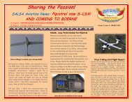
Schematic of preflight inspectionAIRCRAFT OPERATING INSTRUCTIONS – VIRUS 912 S-LSA GLIDER1 Engine, engine cover 8 Right wing - trailingedge15 Hor. tail surfaces(left)2 Gascolator 9 Right air brake 16Fuselage, continued(left)3 Spinner, Nose wheel 10 Fuselage (RH side) 17 Fuselage (LH side)4 Propeller 11Fuselage, continued(right)18 Left air brake56Undercarriage, RHwheelRight wing - leadingedge12 Hor. tail surfaces (right) 19Left wing - trailingedge13 Vert. tail surfaces (right) 20 Left wingtip, lights7 Right wingtip, lights 14 Vert. tail surfaces (left) 2122Left wing - leadingedgeUndercarriage, LHwheelEngine, engine cover Cooling fluid level: half way to the top Oil quantity: within designated limits Throttle, choke and oil pump wires: no mechanical damage, smooth and unobstructedmovement Radiators and hoses: no mechanical damage and/or leakage, air filters clean andintact Exhaust pipes and muffler: firmly in position, no cracks, springs intact and inPage 22
AIRCRAFT OPERATING INSTRUCTIONS – VIRUS 912 S-LSA GLIDERposition, rubber dumpers intact Fuel and/or oil leakage: no fluid on hoses, engine housing or engine cover Reduction gearbox: check for eventual oil leakage, all bolts and plugs attached firmly Fasteners and engine cover screws: tightened, engine cover undamagedGascolator Drain approximately 1 cup of fuel and check for contamination.Spinner Prop: no mechanical damage (e.g. cracks, impact spots), screws tight bolts and nuts:secured Nose wheel: grab aircraft’s propeller and push it towards the ground to verify propernose wheel suspension operation. Then lift the nose wheel off the ground and check for nose leg strut free play. Bolts: fastened Tire: no cracks, adequate pressure Wheel fairing: undamaged, firmlyattached, clean (e.g. no mud or grass on the inside)Propeller Hub and blades: no mechanical damage (e.g. cracks), both immaculately clean Bolts and nuts: secured Auto-feathering mechanism (optional): smooth travel of propeller pitch, adequate spring tensionUndercarriage, wheelsPage 23
AIRCRAFT OPERATING INSTRUCTIONS – VIRUS 912 S-LSA GLIDER Bolts: fastened Landing gear strut: no mechanical damage (e.g. cracks), clean Wheel: no mechanical damage (e.g. cracks), clean Wheel axle and nut: fastened Oil line (hydraulic brakes): no mechanical damage and/or leakage Tire: no cracks, adequate pressure Wheel fairing: undamaged, firmly attached, clean (e.g. no mud or grass on the inside)Wings’ leading edge Surface condition: pristine, no cracks, impact spots, no paint and/or edge separations Pitot tube: firmly attached, no mechanical damage or bending. Remove protection coverand make sure it is not blocked or full of water. Wing drain holes: make sure they are not blocked and clean accordingly.Wingtip, lights Surface condition: pristine, no cracks, impact spots or bumps, no paint separationsWings’ trailing edge Surface condition: pristine, no cracks, impact spots, no paint and/or edge separationsPage 24
AIRCRAFT OPERATING INSTRUCTIONS – VIRUS 912 S-LSA GLIDER Mylar sealing tape between wing and aileron: undamaged and in position Aileron: pristine surface, no cracks and/or impact spots, no paint abnormalities and edgeseparations, no vertical or horizontal free play, smooth and unobstructed deflectionsAirbrakes, fuel reservoir cap Air brakes: firm, smooth, equal and unobstructed extension, tightly fitted whenretracted, springs stiff and intact. Fuel reservoir cap: fastened. Make sure the vent pipe is completely clean.Fuselage, antenna, rescue parachute cover Self-adhesive tape: in position, no separations Controls’ cap, antenna: firmly attached. Station 17 - optional side access door to the cargo compartment: closed and lockedPage 25
AIRCRAFT OPERATING INSTRUCTIONS – VIRUS 912 S-LSA GLIDERFuselage, continued Surface condition: pristine, no cracks, impact spots or bumps, no paint separationsHorizontal tail surfaces Surface condition: pristine, no cracks, impact spots or bumps, no paint and/or edgeseparations Hinges: no free play in any direction Central securing screw on top of the horizontal stabilizer: fastened and secured Self-adhesive tape covering the gap between horizontal and vertical tail surfaces: inposition Elevator: smooth and unobstructed up-down movement, no side-to-side free playVertical tail surfaces Vertical fin bottom part: no cracks, impact spots or paint separations along main chord Surface condition: pristine, no cracks, impact spots or bumps, no paint separations Hinges: no free play in any direction Rudder cable endings: intact, bolts in positionPage 26
AIRCRAFT OPERATING INSTRUCTIONS – VIRUS 912 S-LSA GLIDERCAUTION! Preflight inspection should be performed by completing all stations 1 through 22!8.2 Powered Glider Normal Procedures. To enter the cabin, first lift the door all the way to thebottom wing surface. The silver knob will grab and secure the door in position. Sit on the cabin’s edgeand support your body by placing hands onto this same cabin edge. Drag yourself into the seat lifting firstonly one leg over the stick for best position. Upon assuming a comfortable seating position, check rudderpedals’ position to suit your size and needs. To lower the door DO NOT attempt to grab and pull door’shandle but gently pull the silver knob instead. To close the door securely, rotate the handle so that itlocks and verify that all three closing points are secured. Fasten the safety harnesses according to yoursize. Adjust the rudder pedals according to your required legroom. The aircraft is equipped with in-flightadjustable rudder pedals, which adjust as follows: Sit inside the cockpit and release the pressure off thepedals. Pull the black knob in front of the control stick to bring the pedals closer to you. To move thepedals further away, first release the pressure of the pedals, then pull on the knob slightly (this willrelease the lock in the mechanism). Now push the pedals forward using with your feet, while keeping theblack adjustment knob in your hand.WARNING! The safety harness must hold you in your seat securely. This is especially important whenflying in rough air, as otherwise you may bump into the tubes and/or spars overhead. Make sure youtighten the bottom straps first, then the shoulder straps8.2.1 Ground Engine Starting.Before engine start-upCAUTION! To ensure proper and safe use of aircraft it is essential for one to familiarize yourselfwith engine’s limitations and engine manufacturer’s safety warnings. Before engine start-upmake sure the area in front of the aircraft is clear. It is recommended to start-up the engine withaircraft’s nose pointing against the wind.Make sure the fuel quantity is sufficient for the planned flight duration. Make sure the pitot tubeis uncovered and rescue parachute safety pin removed. Engage wheel brakes. If equipped withthe parking brake, engage parking brake.Page 27
Engine start-upAIRCRAFT OPERATING INSTRUCTIONS – VIRUS 912 S-LSA GLIDERMake sure both fuel valves are open and master switch in OFF position (key full left).Should theengine be cold, apply choke (lever full back). Set master switch ON (key in full right position). Setboth magneto switches ON. Avionics OFF. Engage engine starter and keep it engaged until theengine starts. Set throttle to 2500 RPM. Slide the choke lever forward gradually.CAUTION! When the engine is very cold, the engine may refuse to start. Should this occur, movethe choke handle fully backwards and hold it there for some 20 seconds to make mixture richer.Engine warm-up procedureThe engine should be warmed-up at 2500 RPM up to the point working temperature is reached.Warming-up the engine you should:1 Point aircraft’s nose into the wind.2 Verify the enginetemperature ranges within operational limits.CAUTION! Avoid engine warm-up at idle throttle as this causes the spark plugs to turn dirty andthe engine to overheat.With wheel brakes engaged and control stick in full back position, first set engine power to 4000RPM in order to perform the ignition check. Set the ignition switches OFF and back ON one byone to verify RPM drop of not more than 300 RPM. When the ignition check has been completed,add full power (throttle lever full forward) and monitor engine’s RPM. Make sure they rangebetween maximum recommended and maximum allowable RPM limits.Note that engine does not reach 5800 RPM on ground. Engines are factory set to reach maximumground RPM of 5300 - 5500 at sea level at 68° F. Maximum ground RPM may vary depending onthe season and service elevation.CAUTION! Should engine’s RPM be lower than the recommended on ground amount (min. 5100RPM) or in excess of maximum allowable RPM on ground (5800) during this maneuver, checkengine and wiring for correct installation.8.2.2 Taxiing.Release parking brake. Taxing technique does not differ from other aircraft equipped with asteerable nose wheel. Prior to taxiing it is essential to check wheel brakes for proper brakingaction. Should you expect to taxi a long way, take engine warm-up time into account and begintaxiing immediately after engine start-up. Warm-up the engine during taxiing so as not to causethe engine to overheat, as prolonged ground operation are likely to do on warm days.Holding point - Make sure the temperatures at full power range are within operational limits.Make sure the safety harnesses are fastened and doors closed and secured at all three closingpoints. Set flaps to 2nd position (flap handle full up). Power to idle.CAUTION! Should the engine start to overheat because of long taxi and holding, shut down theengine and wait for the engine temperatures drop to reasonable values. If possible, point theaircraft’s nose into the wind. This will provide radiators with airflow to cool down the enginefaster.Page 28
AIRCRAFT OPERATING INSTRUCTIONS – VIRUS 912 S-LSA GLIDER8.2.3 Normal Takeoff.Before lining up, verify the following:Parking brake (if applicable): disengaged (full forward). Air brakes (if applicable): retracted andsecured. Fuel valves: fully open. Fuel quantity: sufficient. Safety harnesses: fastened. Cabindoors: closed securely Trim handle: in neutral position or slightly forward. Flap handle: 2ndposition (flap handle full up) Runway: clear - Release brakes, line up and apply full power. Verifyengine for sufficient RPM at full throttle (min 5100 RPM).CAUTION! Keep adding power gradually.WARNING! Should engine RPM not reach more than 5000 RPM when at full throttle, ABORTTAKE-OFF IMMEDIATELY, come to a standstill and verify that the propeller is at minimum pitchsetting .Start the takeoff roll pulling the control stick one third backward and lift the nose wheel off theground as you accelerate. Reaching 40-43 kts, gently pull on the stick to get the aircraft airborne.CAUTION! Crosswind (max 15 kts) takeoff should be performed with the control stick pointedinto the wind. Special attention should be paid to maintaining runway heading!Initial climbWhen airborne, engage brakes momentarily to prevent in-flight wheel spinning. Accelerate atfull power and later maintain proper climbing speed. As you reach 50 kts (90 km/h) at above 150ft (50 m), set flaps to 1st stage, reaching 60 kts (110 km/h) at 300 ft (100 m) set flaps to neutralposition. Reduce RPM by 10% or below 5500 RPM and continue climbing at 70 kts (130 km/h).Adjust the trim to neutralize the stick force if necessary. Remember to keep the temperaturesand RPM within operational limits during climb out.CAUTION! Reduce power and lower the nose to increase speed in order to cool the engine downif necessary.Should you be climbing for a cross-country flight, consider climbing at 100 kts (185 km/h) as thiswill greatly increase your overall travelling speed. Reaching cruise altitude, establish horizontalflight and set engine power to cruise (5300 RPM).CruiseWhen horizontal flight has been established, verify on-board fuel quantity again. Keep theaircraft balanced while maintaining desired flight parameters. Should you desire to cruise at lowspeed (up to 80 kts (150 km/h)), set flaps to neutral position other-wise flaps should be set tonegative position (flap handle full down).Check engine operation and flight parameters regularly! Recommended cruise is at 5300 RPM,with a fuel burn of 3.3 US gal per hour.Page 29
AIRCRAFT OPERATING INSTRUCTIONS – VIRUS 912 S-LSA GLIDERCAUTION! It is not recommended to fly the aircraft at speeds exceeding 80 kts (150 km/h) usingflap setting other than negative.CAUTION! Check fuel upon establishment of cruise attitude. Because of the fuel system design,the fuel tends to gradually cross-flow from the right tank to the left. To prevent this, shut theright fuel valve and open it again when the fuel level inside left tank has lowered.CAUTION! If the fuel quantity in a fuel tank is low, it is possible that the engine starts to suck airinto the fuel system. To prevent this and consequent engine failure, always close the fuel valve ofthe tank where the fuel quantity is very low.Cruising in rough conditions. Should you experience turbulence, reduce airspeed to V A , 76 kts,and continue flying with flaps set to neutral position.CAUTION! In rough air, reduce engine power if necessary to keep airspeed below V A .Descent and final approachDescend at speeds at or below V A and flaps in negative stage. To expedite descents, useairbrakes (if applicable) and keep airspeed below VAE. For approach, reduce speed to 70 kts (130km/h) and set flaps to 1st position only after turning to base leg. Adjust engine power tomaintain proper airspeed. Set trim to neutralize stick force if necessary. During the descentmonitor temperatures and keep within operational limits.CAUTION! During the descent, engine power MUST be reduced. Should you be forced todescend at idle power, make sure you keep adding throttle for short periods of time, this willhelp to keep spark plugs clean.CAUTION! With flaps in 2nd position, no more than half of the available aileron deflection ispermitted.On final, set flaps to 2nd position. Align with the runway and reduce power to idle. Extendairbrakes (as required) and maintain an airspeed of 55 kts (102 km/h). Instead of throttle useairbrakes to control your descent glide path. Otherwise, control your attitude and crab or slip asnecessary.CAUTION! Crosswind landings require higher final approach speeds to ensure aircraft’s safemaneuverability. Increase the approach speed by 1 kts for every 1 kts of crosswind componente.g. in case of 5 kts crosswind component, increase the approach speed by 5 kts.Roundout and touchdownCAUTION! See chapter “Performance” for landing performance.Roundout and touchdown (flare) occurs at following airspeeds:CAUTION! Land the aircraft in such a manner that the two main wheels touch the ground first,allow the nose-wheel touchdown only after speed has been reduced below 25 kts. Whenlowering the nose wheel to the runway, rudder MUST NOT be deflected in any direction (rudderpedals centered).Page 30
AIRCRAFT OPERATING INSTRUCTIONS – VIRUS 912 S-LSA GLIDERWhen on ground, start braking action holding the control stick in full back position. Steer theaircraft using brakes and rudder only. Provided the runway length is sufficient, come to acomplete standstill without engaging the brakes holding the control stick slightly backwards asyou decelerate.WARNING! After touchdown, DO NOT retract airbrakes immediately, as this causes sudden liftincrease and the aircraft may rebound off the ground. Should this occur, hold the elevatorsteady; under no circumstances attempt to follow aircraft’s movement with elevator movements,for <strong>Virus</strong> 912 LSA tends to stabilize rebounding by itself. However, it is important to maintain runwayheading using the rudder at all times. Retract air brakes only after the aircraft has come to acomplete standstill.CAUTION! Should you be performing the touch-and-go maneuver, retract air brakes care-fullybefore re-applying full power.Crosswind approach and roundoutCAUTION! Crosswinds prolong landing runway length due to elevated airspeed that should beused, see previous page.Performing a crosswind landing, the wing-low method should be used. When using the wing-lowmethod it is necessary to gradually increase the deflection of the rudder and aileron to maintainthe proper amount of drift correction.WARNING! If the crab method of drift correction has been used throughout the final approachand roundout, the crab must be recovered the before touchdown by applying rudder to align theaircraft’s longitudinal axis with its direction of movement.8.2.4 Engine extraction and retraction. N/A8.2.5 Best Rate of Climb Speed. V Y = 70 kts; V X = 52 kts. Speeds greater than 70 ktsmay be preferable on warm days as rate of climb remains strong at speeds beyond 90 kts.8.2.6 In-Flight Starting the Engine. V ES is the Maximum velocity for engine restart inflight 50 kts. This is applicable only for the auto-feathering propeller version! Do not restart theengine in flight beyond this speed.NOTE: This procedure applies only for stopping and restarting the engine following anintentional unpowered flight. Reduce speed to 50 kts or below. Apply normal engine shut downor start-up procedure. Upon restart, should the engine cool down during unpowered flight, applychoke. Always start the engine at idle throttle.CAUTION! Do not add full power while the engine is still cool. Fly at lower airspeeds at low powerengine setting to warm it up instead (e.g. 50 kts (90 km/h) at 3000 RPM).8.2.7 In Flight Shutdown of Engine. This procedure applies only for stopping andrestarting the engine following an intentional unpowered flight. Reduce speed to 50 kts orPage 31
AIRCRAFT OPERATING INSTRUCTIONS – VIRUS 912 S-LSA GLIDERbelow. Apply normal engine shut down or start-up procedure. Upon restart, should the enginecool down during unpowered flight, apply choke. Always start the engine at idle throttle.8.2.8 Ground Shutdown.1. Engine speed - idling2. Instruments - engine instruments within limits3. COMM + intercom - off4. Ignition key - off5. Circuit breakers - off6. Master switch - offCome to a complete standstill by engaging brakes. Re-check RPM drop by switching ignition OFFand back ON, one by one. Leave the engine running at idle RPM for a minute in order to cool itdown. Set master switch and ignition switches in OFF position.Unlock air brakes (handle hanging down freely) and insert parachute rescue system handle’ssafety pin (if rescue system installed). Apply parking brake, if fitted. Open cabin door, unfastensafety harnesses and exit the cockpit (watch for the wheel fairings!). Block the wheels and securethe pitot tube by putting on a protection cover. Fit the tubes onto fuel tank vents so that fuel willnot spill onto the wing in event of full fuel tanks, temperature expansion of fuel and/or parkingon a slope. It is recommended to shut both fuel tank valves.CAUTION! Should the aircraft be parked on a slope it is recommended to shut one of the fuelvalves to prevent overflowing of the adjacent fuel tank.8.3 Cruise. <strong>Aircraft</strong> at MTOM, recommended cruise power of 5300 RPM at 15°C / 59°F at sealevel altitude, flaps set to negative position (-5 degrees): <strong>Virus</strong> 912 LSA - cruise airspeed 116 ktsBest economy cruising level is 7500 ft. There, cruise performance is equivalent or better than above dueto IAS-TAS relation, but fuel consumption is lower. At these parameters the fuel burn is 3.2 US gal (12.2l)per hour. For detailed fuel consumption determination for various cruising regimes consult the Rotax 912UL/ULS Operators manual.CAUTION! It is not recommended to fly the aircraft at speeds exceeding 80 kts (150 km/h) usingflap setting other than negative.CAUTION! If the fuel quantity in a fuel tank is low, it is possible that the engine starts to suck airinto the fuel system. To prevent this and consequent engine failure, always close the fuel valve ofthe tank where the fuel quantity is very low.Cruising in rough conditions:Should you experience turbulence, reduce airspeed and continue flying with flaps set to neutral position.CAUTION! In rough air, reduce engine power if necessary to keep airspeed below V A (76 kts).8.4 Approach. Descending with the <strong>Virus</strong> is the stage of flight where the most care should betaken. As the aircraft is essentially a glider, it is very slippery and builds up speed very fast.Start the descent by reducing throttle and keep your speed below V RA .During initial descent it is recommended you trim for a 10 kts lower speed than the one you decided todescent at. Do this for safety. In case you hit turbulence simply release forward pressure on the stick andthe aircraft will slow down. Also, keep in mind you need to begin your descent quite some time beforePage 32
AIRCRAFT OPERATING INSTRUCTIONS – VIRUS 912 S-LSA GLIDERdestination. A comfortable rate of descent is 500 fpm (2.5 m/s). So it takes you some 2 minutes for a1000 ft (300 m) drop. At 105 kts (200 km/h) this means 3.6 NM for each 1000 ft drop. Upon entering thetraffic pattern the aircraft should be slowing down. In order to do this, hold your altitude and reducethrottle to idle. When going below 80 kts (150 km/h), set flaps to neutral position. Set proper engineRPM to maintain speed of 70 kts (130 km/h). Trim the aircraft for comfortable stick forces. Beforeturning to base-leg, reduce power to idle and set flaps to 1st stage at 60 kts (110 km/h). Once out of theturn, reduce speed towards 55 kts (100 km/h). Power remains idle from the point of turning base all theway to touch-down. If you plan your approach this way, you will always be on the safe side - even if yourengine fails, you will still be able to safely reach the runway! Turn to final at 55 kts (100 km/h). When inrunway heading, set flaps to 2nd stage. Operate the air-brakes to obtain the desired descent path.How to determine how much airbrakes you need for a certain airspeed?Open them half-way and observe the runway. If the runway threshold is moving up, you are droppingtoo fast - retract the airbrakes a little. If the runway threshold is disappearing below your aircraft, youare dropping too slowly - extend airbrakes further. When working on airbrakes, it is important to keepthe airspeed/pitch angle constant throughout final all the way to flare! The airbrakes will not impact yourspeed, just rate (angle) of descent. For pilots who are not used to operating airbrakes but throttleinstead, keep in mind that airbrakes in <strong>Virus</strong> work just like throttle does: handle back equals less throttle,handle forward equals more throttle.CAUTION! Never drop the airbrakes handle when using them, keep holding the handle even if you arenot moving it!8.5 Landing. Roundout and touchdown (flare) occurs at following airspeeds:o Calm Air at MTOW: 40 ktso Rough Air (including cross-winds: 42 ktsCAUTION! Land the aircraft in such a manner that the two main wheels touch the ground first, allow thenose-wheel touchdown only after speed has been reduced below 25 kts. When lowering the nose wheelto the runway, rudder MUST NOT be deflected in any direction (rudder pedals centered).When on ground, start braking action holding the control stick in full back position. Steer the aircraftusing brakes and rudder only. Provided the runway length is sufficient, come to a complete standstillwithout engaging the brakes holding the control stick slightly backwards as you decelerate.WARNING! After touchdown, DO NOT retract airbrakes immediately, as this causes sudden lift increaseand the aircraft may rebound off the ground.Should this occur, hold the elevator steady; under no circumstances attempt to follow aircraft’smovement with elevator movements, for <strong>Virus</strong> 912 LSA tends to stabilize rebounding by itself. However,it is important to maintain run-way heading using the rudder at all times. Retract air brakes only after theaircraft has come to a complete standstill.CAUTION! Should you be performing the touch-and-go maneuver, retract air brakes care-fully before reapplyingfull power.Crosswind approach and roundoutPage 33
AIRCRAFT OPERATING INSTRUCTIONS – VIRUS 912 S-LSA GLIDERCAUTION! Crosswinds prolong landing runway length due to elevated airspeed that should be used, seeprevious page.Performing a crosswind landing, the wing-low method should be used. When using the wing-low methodit is necessary to gradually increase the deflection of the rudder and aileron to maintain the properamount of drift correction.WARNING! If the crab method of drift correction has been used throughout the final approach androundout, the crab must be undone before touchdown by applying rudder to align the aircraft’slongitudinal axis with its direction of movement.ParkingCome to a complete standstill by engaging brakes. Re-check RPM drop by switching ignition OFF and backON, one by one. Leave the engine running at idle RPM for a minute in order to cool it down. Set masterswitch and ignition switches to OFF. Unlock air brakes (handle hanging down freely) and insertparachute rescue system handle’s safety pin (if rescue system installed). Apply parking brake, if fitted.Open cabin door, unfasten safety harnesses and exit the cockpit (watch for the wheel fairings!). Block thewheels and secure the pitot tube by putting on a protection cover. Fit the tubes onto fuel tank vents sothat fuel will not spill onto the wing in event of full fuel tanks, temperature expansion of fuel and/orparking on a slope. It is recommended to shut both fuel tank valves.CAUTION! Should the aircraft be parked on a slope it is recommended to shut one of the fuel valves toprevent overflowing of the adjacent fuel tank.Stall recovery8.6 Information on Stalls, Spins, and other useful pilot information.1. First reduce angle of attack by pushing the control stick forward, then2. Add full power (throttle lever in full forward position)3. Resume horizontal flight.Spin recovery<strong>Virus</strong> 912 LSA is constructed in such manner that it is difficult to be flown into a spin, and even so, only ataft center of gravity positions. However, once in a spin, intentionally or unintentionally, react as follows:1 Set throttle to idle (lever in full back position).2 Apply full rudder deflection in the direction opposite the spin.3 Lower the nose towards the ground to build speed (stick forward).4 As the aircraft stops spinning neutralize rudder deflection.5 Slowly pull up and regain horizontal flight.NOTE: <strong>Virus</strong> 912 LSA tends to reestablish straight and level flight by itself usually after having spun for amere 45°-90°.WARNING! Keep the control stick centered along its lateral axis (no aileron deflections throughout therecovery phase! Do not attempt to stop the aircraft from spinning using ailerons instead of rudder!Page 34
AIRCRAFT OPERATING INSTRUCTIONS – VIRUS 912 S-LSA GLIDERWARNING! After having stopped spinning, recovering from the dive must be performed using gentle stickmovements (pull), rather than overstressing the aircraft. However, VNE must not be exceeded during thismaneuver.When the aircraft is wings-level and flies horizontally, add throttle and resume normal flight.Handling and maintenance of the GRS Rescue Parachute System.Prior to every flight all visible parts of the system must be checked for proper condition. Specialattention should be paid to corrosion on the activation handle inside the cockpit. Also, main fasteningstraps on the outside of the fuselage must be undamaged at all times. Furthermore, neither system, norany of its parts should be exposed to moisture, vibration and UV radiation for long periods of time toensure proper system operation and life.CAUTION! It is strongly recommenced to thoroughly inspect and grease the activation handle, preferablyusing silicon spray, every 50 flight hours. All major repairs and damage repairs MUST be done by themanufacturer or authorized service personnel.For all details concerning the GRS rescue system, please see the “GRS - Galaxy Rescue System Manual forAssembly and Use”.How fast is too fast?Based on two recent unfortunate events, where two pilots lost their newly acquired Sinus and <strong>Virus</strong>aircraft, the team of <strong>Pipistrel</strong>’s factory pilots decided to stress the importance of airspeed even more. Doread this passage thoroughly as everything mentioned below affects you as the pilot directly!The two eventsBoth the events took place during the first couple of hours pilots flew with their new aircraft. Thereforeit is clear that they had not become completely familiar with all the flight capabilities offered by the Sinusand <strong>Virus</strong>. The circumstances of both the events were remarkably similar. Soon after the pilots picked uptheir new aircraft at the distributor’s facility, the aircraft were severely damaged aloft. One accidentoccurred during the first home-bound cross country flight; and the other during the first flights at itsdomestic airfield. Please note that the distributor had independently tested both mentioned aircraft upto V NE at altitudes of 300 to 500 meters (900 to 1500 feet) without any problems. The new owner/pilots,it was learned, flew their aircraft at higher altitudes, and very high speeds. One of them deployedairbrakes (spoilers) at a speed of 285 km/h (155 kts) - where the V NE of the aircraft was only 225 km/h(122 kts), the other was flying at 3000 m (10.000 ft) at 270 km/h (145 kts) IAS - where the VNE of the aircraftwas 250 km/h (135 kts).They both encountered severe vibrations caused by flutter. As a result, one aircraft’s fuselage broke inhalf just behind the cabin (the crew was saved thanks to the parachute rescue system), the other aircraftsuffered less serious damage, as only the flaperon control tubes were broken. The pilot of the secondmachine then landed safely using elevator and rudder only. Fortunately both pilots survived the accidentwithout injury. Thanks to the Brauniger ALPHA Multifunction Display’s (MFD) integrated Flight DataRecorder, we were able to reconstruct the flights and reveal what had really happened. What was thereason for the flutter causing both accidents? Both pilots significantly exceeded VNE. With the IAS toTAS correction factor taken into consideration, they were both flying faster than 315 km/h (170 kts)!Page 35
AIRCRAFT OPERATING INSTRUCTIONS – VIRUS 912 S-LSA GLIDERYou might say: “Why did they not keep their speed within safe limits? How could they be so thoughtlessto afford themselves exceeding the V NE ?” Speaking with the two pilots they both confessed they wentover the line inadvertently. “Everything just happened so suddenly!” was what they both said. Thereforeit is of vital importance to be familiar to all factors that might influence your flying to the point ofaccidentally exceeding the V NE .Here is the relationship between the human factor and performance: The human body is not intendedto be travelling at 250 km/h (135 kts), nor is it built to fly. Therefore, in flight, the human body and itssignals should not be trusted. To determine the speed at which you are travelling, one normally reliesupon two senses – the hearing and sight. The faster the objects around are passing by, the faster one istravelling. True enough. The louder the noise caused by air rushing past the airframe, the faster onemust be cruising. True again. But let us confine ourselves to the scenarios associated with both of theseevents. At higher altitudes, human eye loses its ability to determine the speed of movement precisely.Because of that pilots, who are flying high up feel like they are flying very slowly. Additionally, it seemsthat at high speeds the air rushing past the airframe ought to cause a tremendous rushing noise. But thisis wrong! In fact, rushing air noise is caused by drag. Modern aircraft like Sinus and <strong>Virus</strong>, manufacturedof composite materials, have so little drag in cruise attitude, that they actually sound quieter than youwould expect. Especially if you are used to wearing a headset when flying you must not rely on your earas the instrument for determining speed. REMEMBER! When flying high, the only reliable tool todetermine airspeed is the cockpit instrument - the airspeed indicator!How to read and understand what the airspeed indicator tells you?Let us first familiarize with the terms used below:IAS: stands for Indicated Airspeed. This is the speed the airspeed indicator reads.CAS: stands for Calibrated Airspeed. This is IAS corrected by the factor of aircraft’s attitude. No pitot tube(device to measure pressure used to indicate airspeed) is positioned exactly parallel to the air flow;therefore the input speed – IAS – must be corrected to obtain proper airspeed readings. With Sinus and<strong>Virus</strong>, IAS to CAS correction factors range from 1.00 to 1.04 (not a big deal). Now for the critical variable-TAS: stands for True Airspeed. TAS is often regarded as the speed of air to which the aircraft’s air-frameis exposed. To obtain TAS you must have CAS as the input value and correct it by pressure altitude,temperature and air density variations. The maximum structural speed is linked to IAS. But light planes,manufactured of carbon reinforced plastics, with long, slick wings are more prone to flutter at highspeeds than to structural failure. So flutter, a function of TAS, is the main factor of determining VNE forus, and most other carbon-reinforced-plastic aircraft producers. Flutter speed is linked to TAS, as it isdirectly caused by small differences in speed of air circulating the airframe. Hence air density is not afactor. For all who still doubt this, here are two quotes from distinguished sources on flutter beingrelated to TAS: “Suffice to say that flutter relates to true airspeed (TAS) rather than equivalent air-speed(EAS), so aircraft that are operated at or beyond their VNE at altitude - where TAS increases for a givenEAS – are more susceptible to flutter...” New Zealand CAA’ Vector Magazine (full passage at page 5 ofhttp://www.caa.govt.nz/fulltext/vector/vec01-4.pdf). “The critical flutter speed depends on TAS, airdensity, and critical Mach number. The air density factor is almost canceled out by the TAS factor; andmost of us won’t fly fast enough for Mach number to be a factor. So TAS is what a pilot must be awareof!” Bob Cook, Flight Safety International. The airspeed indicator shows you the IAS, but this is sadlyNOT the speed of air to which the aircraft’s airframe is exposed. IAS and TAS are almost the same at sealevel but can greatly differ as the altitude increases. So flying at high altitudes, where the air is thinner,results in misinterpreting indicated airspeed. The indicated airspeed value may actually be much lowerthan speed of air to which the aircraft is exposed, the TAS. So is VNE related to IAS or TAS? Although theredline on our altimeter may imply that it is associated with IAS, in reality, for all gliders which arePage 36
AIRCRAFT OPERATING INSTRUCTIONS – VIRUS 912 S-LSA GLIDERinherently prone to flutter, V NE must be assumed to be a TAS reading. The two owners mentioned abovefound out the hard way that this is a fact.How much difference is there between IAS and TAS in practical terms?Data is for standard atmosphere. To obtain correct speeds for particular atmospheric conditions pleasetake advantage of the conversion tables which follow:The table below indicates how fast you may fly at a certain altitude to maintain constant True Air Speed(TAS).The table below indicates how TAS increases with altitude while keeping IAS constant.As you can see from the table above the differences between IAS and TAS are substantial at altitude, andMUST be respected at all times!REMEMBER!Do not trust your ears.Do not trust your eyes.Trust the instruments and be aware of the IAS to TAS relationship!Keep that in mind every time you go flying. <strong>Pipistrel</strong> wishes you happy landings!Myth: One can fully deflect the controls as long as he or she is flying below maneuvering speed.Page 37
AIRCRAFT OPERATING INSTRUCTIONS – VIRUS 912 S-LSA GLIDERThis is flat wrong! The wing structure in light planes is usually certified to take +3.8 G’s, -1.52 G’s (plus acertain safety factor). Put more load on the wing than that and you can lose a wing. But here is the nicepart: below a certain speed, the wing simply cannot put out a full 3.8 G’s of lift! It will stall first! Thisspeed is called Maneuvering Speed or V A . Maneuvering Speed is defined as the maximum speed theplane can be flying at and still stall before the wing breaks no matter how much you pull back on thestick. If you are going slower than the V A and you pull the stick all the way back, the wing will stall withoutbraking physically. If you are going faster than the V A and you pull the stick all the way back, the wing canput out so much lift that it can be expected to break. Therefore people think they can deflect the stick asmuch as they desire below Maneuvering Speed and stay alive. Right? No, wrong! This is a trick question.The Maneuvering Speed is based on pulling back on the stick, not pushing it forward! Note what wassaid above: The V A is defined as how fast you can fly and not be able to put out more than 3.8 G’s of lift.But while the plane is certified for positive 3.8 G’s, it is only certified for a negative G-load of 1.52 G’s! Inother words, you can fail the wing in the negative direction by pushing forward on the stick well belowthe V A ! Few pilots know this.Also, for airliners, certification basis require that the rudder can be fully deflected below ManeuveringSpeed, but only if the plane is not in a sideslip of any kind! (e.g. crab method of approach) Does this makesense at all? Why would you need to fully deflect the rudder if not to re-establish wings-level flight?In a wonderfully-timed accident shortly after Sept. 11th, 2001; which many first thought an act ofterrorism, an Airbus pilot stomped the rudder in wake turbulence while the plane was in a considerablesideslip. The combined loads of the sideslip and the deflected rudder took the vertical stabilizer to itscritical load. A very simple numerical analysis based on the black box confirmed this. The airplane lost itsvertical stabilizer in flight and you know the rest. Also, if you are at your maximum allowable g-limit (e.g.3.8) and you deflect the ailerons even slightly, you are actually asking for more lift from one wing thanthe allowable limit! Therefore combined elevator and aileron deflections can break the plane, even if theelevator is positive only!SO, WHEN YOU THINK THAT YOU CAN DO AS YOU PLEASE WITH THE CONTROLS BELOW MANEUVERINGSPEED, YOU ARE WRONG!9. AIRCRAFT GROUND HANDLING AND SERVICING.9.1 Ground Handling.Engine start-upMake sure both fuel valves are open and master switch in OFF position (key full left).Should theengine be cold, apply choke (lever full back). Set master switch ON (key in full right position). Setboth magneto switches ON. Avionics OFF. Engage engine starter and keep it engaged until theengine starts. Set throttle to 2500 RPM. Slide the choke lever forward gradually.CAUTION! When the engine is very cold, the engine may refuse to start. Should this occur, movethe choke handle fully backwards and hold it there for some 20 seconds to make mixture richer.Engine warm-up procedureThe engine should be warmed-up at 2500 RPM up to the point working temperature is reached.Warming-up the engine you should:1 Point aircraft’s nose into the wind.2 Verify the enginetemperature ranges within operational limits.CAUTION! Avoid engine warm-up at idle throttle as this causes the spark plugs to turn dirty andthe engine to overheat.Page 38
AIRCRAFT OPERATING INSTRUCTIONS – VIRUS 912 S-LSA GLIDERWith wheel brakes engaged and control stick in full back position, first set engine power to 4000RPM in order to perform the ignition check. Set the ignition switches OFF and back ON one byone to verify RPM drop of not more than 300 RPM. When the ignition check has been completed,add full power (throttle lever full forward) and monitor engine’s RPM. Make sure they rangebetween maximum recommended and maximum allowable RPM limits.NOTE: The engine should not reach 5800 RPM on the ground. Engines are factory set to reachmaximum ground RPM of 5300 - 5500 at sea level at 68° F. Maximum ground RPM may varydepending on the season and service elevation.CAUTION! Should engine’s RPM be lower than the recommended on ground amount (min. 5100RPM) or in excess of maximum allowable RPM on ground (5800) during this maneuver, checkengine and wiring for correct installation.TaxiRelease parking brake. Taxing technique does not differ from other aircraft equipped with asteerable nose wheel. Prior to taxiing it is essential to check wheel brakes for proper brakingaction. In the case you expect o taxi a long way, take engine warm-up time into account andbegin taxiing immediately after engine start-up. Warm-up the engine during taxi so as not tocause engine overheating because of prolonged ground operation.Holding pointMake sure the temperatures at full power range are within operational limits. Make sure thesafety harnesses are fastened and doors closed and secured at all three closing points. Set flapsto 2nd position (flap handle full up). Power reduced to idle.CAUTION! Should the engine start to overheat because of long taxi and holding, shut down theengine and wait for the engine temperatures drop to reasonable values. If possible, point theaircraft’s nose into the wind. This will provide radiators with airflow to cool down the enginefaster.9.2 Servicing.Tie downPoint the aircraft into the wind and retract flaps fully. Chock all three wheels. Remove the capscovering mounting holes on the bottom part of the wing (located 15 ft from the fuselage) andcarefully screw in the two screw-in rings provided. Secure tie-down ropes to the wing tie-downrings at an approximately 45-degree angle to the ground. When using rope of a non-syntheticmaterial, leave sufficient slack to avoid damage to the aircraft, should the ropes contract. To tiedown the tail, tie a rope through the tail skid and secure it to the ground. At the end, cover thepitot tube with a protection cover.Draining and refuelingPage 39
AIRCRAFT OPERATING INSTRUCTIONS – VIRUS 912 S-LSA GLIDERWhenever draining or refueling, make sure master switch is set to OFF (key in full left position).Draining the fuel system:The gascolator is located beneath the bottom engine cover on the left hand side of the fuselage.To drain the fuel system, open the drain valve on the gascolator. Drain approximately 1/2 cup offuel. Try to prevent ground pollution by collecting the fuel with a canister. To close the valve,simply turn it in the opposite direction. Do not use force or special tools!CAUTION! Always drain the fuel system before moving the aircraft. This ensures any water orparticles will be drained and not remixed and remain in the fuel tanks.RefuelingCAUTION! Before refueling, it is necessary to ground the aircraft!Refueling can be done by pouring fuel through the fuel tank openings on top of the wings or byusing the single point fueling valve on the lower firewall.Refueling using the electrical fuel pump: First, make sure the fuel hoses are connected to wingconnectors and that both fuel valves are open. Connect one end of the fuel pump to the valvebeneath the bottom engine cowl. Submerge the other end of the fuel pump, which has a filterattached, into the fuel container. Engage the fuel pump by engaging the 12 V socket switch onthe instrument panel. After refueling, it is recommended to prevent air pockets from forminginside the fuel system, that the pilot drains some fuel with both fuel valves fully open. Also,leave the engine running at idle power for a couple of minutes prior to taking-off, and test theengine at full power for a minimum of 30 seconds before takeoff roll begins.Should you be experiencing slow refueling with the electrical fuel pump, you should replace thefilter. You can use any fuel filter for this application. It is recommended to use additional plastictubes attached to the fuel tank vents and leading to the ground in order to avoid over-spills offuel onto the airframe when filling the tanks completely.CAUTION! Use authorized plastic containers to transport and store fuel only! Metal canisterscause water to condense on the inside, which may lead to engine failure.Engine lubrication systemRotax 912 is a four-stroke engine, equipped with a dry sump and lubricated centrally with use ofits own oil pump. All the oil needed is located inside an outer canister. When the engine isrunning, the oil cools by passing through a radiator, located on the left-hand side of the bottomengine cover. The oil quantity can be checked visually with the oil level bar. Make sure the oilquantity is sufficient (within marked limits) at all times.CAUTION! Oil temperature, pressure, and quality is precisely defined and must not, under anycircumstances, vary from the placards and standards.Page 40
AIRCRAFT OPERATING INSTRUCTIONS – VIRUS 912 S-LSA GLIDERSchematic of engine lubrication systemCleaning of aircraft including windscreen and windows.Use fresh water and a soft piece of cloth to clean the aircraft’s exterior. If you are unable toremove certain spots, consider using mild detergents. Afterwards, rinse the entire surfacethoroughly. Lexan glass surfaces are protected by an anti-scratch layer on the outside and ananti-fog coating on the inside of the cabin. Always use fresh water only to clean the glasssurfaces, not to damage these protection layers and coatings. To protect the aircraft’s surface(excluding glass surfaces) from the environmental contaminants, use best affordable car wax. Theinterior is to be cleaned with a vacuum cleaner.Page 41
AIRCRAFT OPERATING INSTRUCTIONS – VIRUS 912 S-LSA GLIDER10. Required Placards and Markings.10.1 Airspeed Indicator Markings. Airspeed indicator calibration (IAS to CAS) - Pitot tube’smounting point and construction makes IAS to CAS correction values insignificant. Thereforepilots should regard IAS to be same as CAS. IAS = CAS.MARKING IAS [kts] DefinitionWhiteband 36 -70Greenband 42 -76Full Flap <strong>Operating</strong> Range. Lower limit is themaximum weight VS0 in landing configuration. Upperlimit is maximum speed permissible with flapsextended.Normal <strong>Operating</strong> Range Lower end is maximumweight VS1 at most forward C.G. with flaps retracted.Upper limit is maximum structural cruising speed.Yellowband76 - 120 Maneuver the aircraft with caution in calm air only.Red line120Maximum speed for all operationsBlue line 70Best climb rate speed (VY)10.2 <strong>Operating</strong> Limitations on instrument panel.InstrumentRed line(minimum)Green arc(normal)Yellow arc(caution)Red line(maximum)Tachometer (RPM)16001600-55005500-58005800Oil temperatureCylinder head temp.50°C (122°F)90-110°C(194-230°F)110-140°C(230-284°F)110-120°C(230-248°F)140°C (284°F)120°C (248°F)Oil pressure1.0 bar (14.5 psi)6.0 bar (87.0 psi)10.3 Passenger warnings.Page 42
AIRCRAFT OPERATING INSTRUCTIONS – VIRUS 912 S-LSA GLIDER10.4 NO INTENTIONAL SPINS BEYOND ¼ TURN (90 o )10.5 Empty weight. 702.5 lbs10.6 Maximum takeoff weight. MTOW – 1210 lbs10.7 Max and min weight of crew. Max Crew Weight 519 lbs, Min Crew Weight 119 lbs.10.8 Seat for solo operations of two seated gliders. Solo pilot may fly in either left or right seat.10.9 Allowable baggage weight. 55 lbs (25 KG)NOTE: If GRS Recovery Chute System is removed, up to 88 lbs (40 KG) of baggage is allowable.Page 43
AIRCRAFT OPERATING INSTRUCTIONS – VIRUS 912 S-LSA GLIDERPlacardsQuantity=13 GallonsQuantity=13 GallonsPage 44
AIRCRAFT OPERATING INSTRUCTIONS – VIRUS 912 S-LSA GLIDER11. Supplementary information.11.1 Familiarization flight procedures. This chapter has been written to assistowners/pilots/instructors of <strong>Virus</strong> 912 LSA on their quest to learn how to safely and efficiently fly thisaircraft in addition to the information already assembled in the rest of this POH. This section will covermost operations the aircraft offers in an order established in section on Normal procedures andrecommended speeds. Please consider what follows as an add-on to that chapter.Engine start-upFirst and foremost make sure you have sufficient fuel quantity on board for the desired length of flight. Ifyou are not completely confident there is enough, step out of the aircraft and add more fuel into thetanks. There is an old aviators’ saying: “The only time you have too much fuel is when you are on fire.”When engaging the engine starter, wheel brakes MUST be engaged. To keep your propeller in perfectcondition, avoid starting up on areas where there are small stones on the ground. Those little stones caneasily be picked up by the propellers causing damage to the blades.Warming up must be conducted below 2500 RPM. When reaching safe operational engine temperatures,verify maximum engine ground RPM. Hold the stick back completely and slowly (!) add throttle to fullpower, then verify RPM.TaxiTaxiing with the <strong>Virus</strong> 912 LSA is rather simple considering the steerable nose wheel. For sharper turns onthe ground you can also use wheel brakes to assist yourself. It is recommended you taxi slow, up to 10km/s (5 kts), while holding the stick back fully to ease the pressure of the nose wheel.During taxiing, monitor engine temperatures. Due to low airflow around the radiators the CHT and Oiltemperature will rise during long taxi periods. If you are holding position, do not leave throttle at idle. It isbetter you have some 2500 RPM as this will provide some airflow from the propeller to the radiators andthe temperatures will not rise so quickly. Should you see engine temperatures exceed safe operationalvalues, shut off the engine, point the aircraft’s nose into the wind and wait for the temperatures toreduce.Take off and initial climbHaving checked and set all engine and aircraft parameters, you should be ready for take-off by now.Re-verify both fuel valves be open and the airbrakes retracted and locked (handle full up). Trim levershould be in the middle.Start the take-off roll gradually. Keep adding throttle slowly and smoothly full power. There are tworeasons for this. First, you change flight stage from zero movement to acceleration slowly; this pro-videsyou with time to react to conditions. Second, especially if taking-off from a gravel runway, this method ofadding full throttle will prevent the little stones on the runway from damaging the propeller. Extremelyshort runways are an exception. There you should line up the aircraft, set flaps to 2nd stage, step on thebrakes, apply full power and release the brakes. As you start to move, pull the stick 1/3 of elevator’sdeflection backwards to ease the pressure on the nose wheel and lift it off the runway slightly. Do not usefull back deflection as this will cause the aircraft’s tail to touch the ground.When the nose wheel has lifted off the ground, there is nothing else but to hold the same pitch attitudeand the aircraft will become airborne. Crosswind take-offs, depending on wind strength, require a littlebit of aileron deflection into the wind. Remember, wings must stay level throughout ground-roll, rotationPage 45
AIRCRAFT OPERATING INSTRUCTIONS – VIRUS 912 S-LSA GLIDERand initial climb! Having lifted off the ground, gently push the stick forward just a bit to accelerate. Atsome 90 km/ h (50 kts) set flaps to 1st stage, at 110 km/h (60 kts) set them to neutral.ClimbA comfortable setting for climb is flaps in neutral position, speed of 70 kts (130 km/h) at or slightly below5500 RPM. In summer time or when outside temperature exceeds 30°C you should consider climbing atsome 85 kts (160 km/h) to provide more airflow to the engine radiators. Trim the aircraft for comfortablestick forces.CruisePassing through 85 kts (160 km/h), set flaps to negative position (handle full down). A comfortable cruisesetting is 5300 engine RPM. As the <strong>Virus</strong> is sensitive to flap settings, especially when it comes to fuelefficiency, ALWAYS use negative stage of flaps beyond 85 kts (160 km/h) and neutral for level flight below70 kts (130 km/h).Cruising fast, do not kick-in rudder for turns! Above 85 kts (160 km/h) the rudder becomes almostinsignificant in comparison to aileron deflections when it comes to making a turn. Cruising fast, it isextremely important to fly coordinated (ball in the middle) as this increases efficiency and de-creasesside-pressure onto vertical tail surfaces. Also, pay attention to turbulence. If you hit turbulence at speedsgreater than VRA, reduce power immediately and pull the nose up to reduce speed. If flying a trafficpattern, keep flaps in neutral position and set engine power so that airspeed does not exceed 80 kts.DescentDescending with the <strong>Virus</strong> is the stage of flight where the most care should be taken. As the aircraft isessentially a glider, it is very slippery and builds up speed very fast. Start the descent by reducing throttleand keep your speed below V A . During initial descent it is recommended you trim for a 10 kts lowerspeed than the one you decided to descent at. Do this for safety. In case you hit turbulence simplyrelease forward pressure on the stick and the aircraft will slow down. Also, keep in mind that you needto begin your descent quite some time before reaching your destination. A comfortable rate of descentis 500 fpm (2.5 m/s). So it takes you some 2 minutes for a 1000 ft (300 m) drop. At 105 kts (200 km/h)this means 3.6 NM for each 1000 ft drop.Entering the traffic pattern the aircraft must be slowing down. In order to do this, hold your altitude andreduce throttle to idle. When going below 80 kts (150 km/h), set flaps to neutral position. Set properengine RPM to maintain speed of 70 kts (130 km/h). Trim the aircraft for comfortable stick forces. Beforeturning to base-leg, reduce power to idle and set flaps to 1st stage at 60 kts (110 km/h). Once out of theturn, reduce speed towards 55 kts (100 km/h). Power remains idle from the point of turning base all theway to touch-down. If you plan your approach this way, you will always be on the safe side - even if yourengine fails, you will still be able to safely reach the runway!Turn to final at 55 kts (100 km/h). When in runway heading, set flaps to 2nd stage. Operate the air-brakesto obtain the desired descent path (if applicable).How to determine how much airbrakes you need for a certain airspeed?Open them half-way and observe the runway. If the runway threshold is moving up, you are dropping toofast - retract the airbrakes a little. If the runway threshold is disappearing below your aircraft, you aredropping too slowly - extend airbrakes further. When working on airbrakes, it is important to keep theairspeed/pitch angle constant throughout final all the way to flare! The airbrakes will not impact yourspeed, just rate (angle) of descent. For pilots who are not used to operating airbrakes but throttlePage 46
AIRCRAFT OPERATING INSTRUCTIONS – VIRUS 912 S-LSA GLIDERinstead, keep in mind that airbrakes in <strong>Virus</strong> work just like throttle does: handle back equals less throttle,handle forward equals more throttle.CAUTION! Never drop the airbrakes handle when using them, keep holding the handle even if you arenot moving it!Roundout (Flare) and touchdownYour speed should be a constant 55 kts (100 km/h) throughout the final with the descent path constantas well. At a height of 10 meters (25 feet) start a gentle flare and approach the aircraft must touch downwith the main (back) wheels first, so that you will not bounce on the runway. After touchdown, operatethe rudder pedals if necessary to maintain runway heading and try to have the nose wheel off the groundfor as long as possible. When the nose wheel is to touch the ground, rudder pedals MUST be exactly inthe middle not to cause damage to the steering mechanism. While braking, hold the stick back fully!Once you have come to a standstill, retract flaps all the way to negative position (handle full down) andretract and lock the airbrakes - handle full up.Should you bounce off the runway after touch-down, do not, under any circumstances, push stickforward or retract airbrakes. Spoilers (airbrakes) stay fully extended, the stick goes backwards slightly.Bouncing tends to reduce by itself – just keep your aircraft pointed straight down the runway.Crosswind landings, depending on the wind speed, require some sort of drift correction. Most efficient isthe low-wing method, where you are to lower the wing into the wind slightly and maintain course byapplying appropriate rudder deflection. You can also try the crab method.Crosswind landings on paved runways (asphalt, concrete, tarmac...)In this case, special attention must be paid to straightening the aircraft before touchdown in order not todamage the undercarriage because of increased surface grip on impact. Should the crosswindcomponent be strong (8 kts and over), it is recommended to gently flare in such a manner, that one ofthe main wheels touches down an instant before the other (e.g. if there is crosswind from your left, theleft wheel should touch down just before the right wheel does). This way the undercarriage is less likelyto be damaged due to side forces.Landing in strong turbulence and/or gusty windsFirst of all, approach airspeed must be increased for half of the value of wind gusts (e.g. if the wind isgusting for 6 kts, add 3 kts to the final approach speed). In such conditions it is recommended to use onlythe 1st stage of flaps for increased maneuverability. In very strong winds (20 kts and more), use neutralflaps (0 deg.) for the complete approach and roundout.ParkingNothing special to add here. Taxi to the apron with flaps in negative position (minimum lift) and spoilersretracted. Again, taxi slowly for reasons mentioned under “Taxi.”. Come to a standstill, shut down theengine, insert the parachute rescue system activation handle’s safety pin, unlock and leave the airbrakeshandle hanging down freely (this reduces stress to airbrake plate’s springs and maintains their stiffness).It is recommended to shut both fuel valves for longer parking or when parked on a slope.11.2 Pilot operating advisories.Parachute rescue system: use, handling and maintenancePage 47
AIRCRAFT OPERATING INSTRUCTIONS – VIRUS 912 S-LSA GLIDERGRS System descriptionThe GRS rocket charged parachute rescue system provides you with a chance to rescue yourself from anunexpected situation. The system is placed inside a durable cylinder mounted on the right hand side ofthe baggage compartment. Inside this cylinder is the parachute which stored inside a deployment bagwith a rocket engine underneath. This brand new design deploys a canopy that is not gradually drawnfrom the container, exposed to distortion by air currents, but it is safely open after 0.4 to 0.7 seconds indistance of 15-18 meters above the aircraft. It is carried there in a special deployment bag, whichdecreases the risk of aircraft debris fouling the canopy. The parachute rescue system is activatedmanually, by pulling the activation handle mounted on the back wall above. After being fired, the mancanopy is open and fully inflated in about 3.2 seconds.WARNING! Activation handle safety pin should be inserted when the aircraft is parked or hangared toprevent accidental deployment. However, the instant pilot boards the aircraft, safety pin MUST beremoved!Typical situations for use of the parachute rescue system are:structural failuremid-air collisionloss of control over aircraftengine failure over hostile terrainpilot incapacitation (incl. heart attack, stroke, temp. blindness, disorientation...)Prior to firing the system, provided time allows:shut down the engine and set master switch to OFF (key in full left position)shut both fuel valvesfasten safety harnesses tightlyprotect your face and body.To deploy the parachute jerk the activation handle hard to a length of at least 1 foot towards theinstrument panel.Once you have pulled the handle and the rocked is deployed, it will be about two seconds before you feelthe impact produced by two forces. The first force is produced by stretching of all the sys-tem. Thesecond force follows after the inflation of the canopy from opening impact and it will seem to you thatthe aircraft is pulled backwards briefly. The airspeed is reduced instantly and the aircraft now starts todescent underneath the canopy.CAUTION! Should you end up in power lines (carrying electrical current), DO NOT under anycircumstances touch any metal parts inside or outside the cockpit. This also applies to anyone attemptingto help or rescue you. Be aware that anyone touching any part of the aircraft while standing on theground will probably suffer mayor injury or die of electrocution. Therefore, you are strongly encouragedto confine your movements until qualified rescue personal arrives at the site to assist you.After the parachute rescue system has been used or if you suspect any possible damage to the sys-tem,do not hesitate and immediately contact the manufacturer!Page 48
AIRCRAFT OPERATING INSTRUCTIONS – VIRUS 912 S-LSA GLIDERGRS Handling and maintenancePrior to every flight all visible parts of the system must be checked for proper condition. Special attentionshould be paid to corrosion on the activation handle inside the cockpit. Also, main fastening straps on theoutside of the fuselage must be undamaged at all times. Furthermore, neither system, nor any of its partsshould be exposed to moisture, vibration and UV radiation for long periods of time to ensure propersystem operation and life.CAUTION! It is strongly recommenced to thoroughly inspect and grease the activation handle, preferablyusing silicon spray, every 50 flight hours. All major repairs and damage repairs MUST be done by themanufacturer or authorized service personnel.For all details concerning the GRS rescue system, please see the “GRS - Galaxy Rescue System Manual forAssembly and Use”.12. MAINTENANCE MANUAL. (See separate document)Page 49