Reference Manual - LYNX Technik AG
Reference Manual - LYNX Technik AG
Reference Manual - LYNX Technik AG
You also want an ePaper? Increase the reach of your titles
YUMPU automatically turns print PDFs into web optimized ePapers that Google loves.
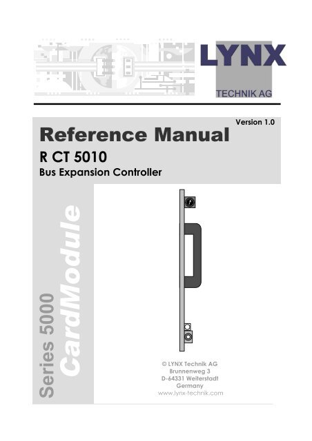
<strong>Reference</strong> <strong>Manual</strong>R CT 5010Bus Expansion ControllerVersion 1.0Series 5000CardModule© <strong>LYNX</strong> <strong>Technik</strong> <strong>AG</strong>Brunnenweg 3D-64331 WeiterstadtGermanywww.lynx-technik.com
<strong>Reference</strong> <strong>Manual</strong> R CT 5010 Version1.0Information in this document is subject to change withoutnotice. No part of this document may be reproduced ortransmitted in any form or by any means, electronic ormechanical for any purpose, without express written permissionof <strong>LYNX</strong> <strong>Technik</strong> <strong>AG</strong>.<strong>LYNX</strong> <strong>Technik</strong> <strong>AG</strong> may have patents, patent applications,trademarks, copyrights or other intellectual property rightscovering the subject matter in this document. Except asexpressly written by <strong>LYNX</strong> <strong>Technik</strong> <strong>AG</strong>, the furnishing of thisdocument does not give you any license to patents,trademarks, copyrights or other intellectual property of <strong>LYNX</strong><strong>Technik</strong> <strong>AG</strong> or any of its affiliates.© <strong>LYNX</strong> <strong>Technik</strong> <strong>AG</strong> 2002 all rights reservedPage 2
Warranty<strong>Reference</strong> <strong>Manual</strong> R CT 5010 Version1.0<strong>LYNX</strong> <strong>Technik</strong> <strong>AG</strong> warrants that the product will be free fromdefects in materials and workmanship for a period of two (2)year from the date of shipment. If this product proves defectiveduring the warranty period, <strong>LYNX</strong> <strong>Technik</strong> <strong>AG</strong> at its option willeither repair the defective product without charge for parts andlabor, or will provide a replacement in exchange for thedefective product.In order to obtain service under this warranty, customer mustnotify <strong>LYNX</strong> <strong>Technik</strong> of the defect before expiration of thewarranty period and make suitable arrangements for theperformance of service. Customer shall be responsible forpackaging and shipping the defective product to the servicecenter designated by <strong>LYNX</strong> <strong>Technik</strong>, with shipping chargesprepaid. <strong>LYNX</strong> <strong>Technik</strong> shall pay for the return of the product tothe customer if the shipment is within the country which the <strong>LYNX</strong><strong>Technik</strong> service center is located. Customer shall be responsiblefor payment of all shipping charges, duties, taxes and any othercharges for products returned to any other locations.This warranty shall not apply to any defect, failure, or damagecaused by improper use or improper or inadequatemaintenance and care. <strong>LYNX</strong> <strong>Technik</strong> shall not be obligated tofurnish service under this warranty a) to repair damage resultingfrom attempts by personnel other than <strong>LYNX</strong> <strong>Technik</strong>representatives to install, repair or service the product; b) torepair damage resulting from improper use or connection toincompatible equipment; c) to repair any damage ormalfunction caused by the use of non <strong>LYNX</strong> <strong>Technik</strong> supplies; ord) to service a product which has been modified or integratedwith other products when the effect of such modification orintegration increases the time or difficulty servicing the product.THIS WARRANTY IS GIVEN BY <strong>LYNX</strong> TECHNIK WITH RESPECT TO THISPRODUCT IN LIEU OF ANY OTHER WARRANTIES, EXPRESS ORIMPLIED. <strong>LYNX</strong> TECHNIK AND ITS VENDORS DISCLAIM ANY IMPLIEDWARRANTIES OF MERCHANTABILITY OR FITNESS FOR A PARTICULARPURPOSE. <strong>LYNX</strong> TECHNIK`S RESPONISIBILITY TO REPAIR ANDREPLACE DEFECTIVE PRODUCTS IS THE SOLE AND EXCLUSIVEREMEDY PROVIDED TO THE CUSTOMER FOR BREACH OF THISWARRANTY. <strong>LYNX</strong> TECHNIK AND ITS VENDORS WILL NOT BE LIABLEFOR ANY INDIRECT, SPECIAL, INCIDENTAL, OR CONSEQUENTALDAM<strong>AG</strong>ES IRRESPECTIVE OF WHETHER <strong>LYNX</strong> TECHNIK OR THEVENDOR HAS ADVANCE NOTICE OF THE POSSIBILITY OF SUCHDAM<strong>AG</strong>ES.Page 3
<strong>Reference</strong> <strong>Manual</strong> R CT 5010 Version1.0Regulatory informationEuropeDeclaration of ConformityWe<strong>LYNX</strong> <strong>Technik</strong> <strong>AG</strong>Brunnenweg 3D-64331 WeiterstadtGermanyDeclare under our sole responsibility that the productTYPE: R CT 5010To which this declaration relates is in conformity with the followingstandards (environments E1-E3):EN 55103-1 /1996EN 55103-2 /1996EN 60950 /2001Following the provisions of 89/336/EEC and 73/23/EEC directives.Winfried DeckelmannWeiterstadt, November 2003Place and date of issueLegal SignaturePage 4USAFCC 47 Part 15This device complies with part 15 of the FCC Rules. Operation issubject to the following two conditions: (1) This device may notcause harmful interference, and (2) this device must accept anyinterference received, including interference that may causeundesired operation.Note: This equipment has been tested and found to comply with thelimits for a Class A digital device, pursuant to the part 15 of the FCCRules. These limits are designed to provide reasonable protectionagainst harmful interference when the equipment is operated in acommercial environment. This equipment generates, uses, and canradiate radio frequency energy and, if not installed and used inaccordance with the instruction manual, may cause harmfulinterference to radio communications. Operation of this equipment ina residential area is likely to cause harmful interference in which casethe user will be required to correct the interference at his ownexpense
<strong>Reference</strong> <strong>Manual</strong> R CT 5010 Version1.0ContentsWarranty ..............................................................................................................3Regulatory information.......................................................................................4Europe................................................................................................................4Declaration of Conformity ........................................................................4USA .....................................................................................................................4FCC 47 Part 15.............................................................................................4Contents...............................................................................................................5Getting Started....................................................................................................7Packaging.........................................................................................................7Product Description .........................................................................................7Functional Diagram .........................................................................................9Module Layout ...............................................................................................10Control System Topology.................................................................................11System Connections ......................................................................................13Configuration Examples................................................................................14Single Controller System. .........................................................................14R CT 5010 used with R CT 5020................................................................15R CT 5010 used with R CT 5030................................................................16Installation .........................................................................................................17Settings and Control .........................................................................................18Rotary Switch Function..................................................................................18Factory Preset Condition.........................................................................18Alarm/LED Status Indicators.............................................................................19General Status LED ...................................................................................19Controller Removal...........................................................................................20<strong>LYNX</strong> Control Software .....................................................................................21Specifications (R CT 5010) ...............................................................................21Parts List..............................................................................................................21Service ...............................................................................................................22Contact Information .........................................................................................23Page 5
<strong>Reference</strong> <strong>Manual</strong> R CT 5010 Version1.0This page is intentionally left blankPage 6
<strong>Reference</strong> <strong>Manual</strong> R CT 5010 Version1.0Getting StartedPackagingThe shipping carton and packaging materialsprovide protection for the module during transit.Please retain the shipping cartons in casesubsequent shipping of the product becomesnecessary.Product DescriptionThe R CT 5010 is a controller option for the R FR 3010and R FR 5010 Rack Frame assemblies and providesremote control, status monitoring and errorreporting for all <strong>LYNX</strong> modules installed in the rack.This board is must be used with an R CT 5020 or R CT5030 controller in a host rack and is an economicalmethod for system expansion beyond a single rack.The basic function is to extend the reach of the RCT 5020 and R CT 5030 controllers into racks thatare in very close proximity to the host.The option consists of the controller hardware only.Software functionality is provided with the <strong>LYNX</strong>control software already supplied with the R CT5020 or R CT 5030 controllers.The R CT 5010 is one component in a scalable andmodular control system topology that can expandfrom a single rack to hundreds of racks located indifferent locations. Other options available are:R CT 5020. Rack Controller. This is the basic rackcontroller and is the first step in building a controlsystem. A Single rack with a RCT 5020 can beexpanded with the R CT 5010 and R CT 5030controllers to form a large integrated system. <strong>LYNX</strong>control software is supplied with this option.Page 7
<strong>Reference</strong> <strong>Manual</strong> R CT 5010 Version1.0R CT 5030. Master Controller. For larger systems, orfor systems requiring network connectivity weprovide the Master Controller. When used with theMaster Software control package this providesnetwork connectivity, a browser style interface andstandard TCP/IP communications. This option is alsorequired for the support of SNMP error reporting.The Master Control Software package is alsoequipped to take more advanced plug in controloptions <strong>LYNX</strong> has under development.Each control system is configured based on theapplication, connectivity requirements and thephysical location of the racks. Care should betaken when specifying the controller options forlarger systems. We can provide assistance in systemdesign if you have some concerns. Please Contactyour local dealer or a <strong>LYNX</strong> office for assistance.Page 8
<strong>Reference</strong> <strong>Manual</strong> R CT 5010 Version1.0Functional DiagramFigure 1 below is the basic functional diagram forthe R CT 5010 CardModule.General StatusRS 232DriverRS 422/485DriverEXTENDRotary Switch(Front ofPCB)ControllerGPI INGPO OUTOptoCouplerALARMSyncSeperatorRef inRef LoopFlashE PromFlashRamJT<strong>AG</strong>ControllerInternal Control BusNote. REFis notsupported onthe R FR 3010JT<strong>AG</strong> Controlleronly used in Series 5000RacksTo Modules (10)Figure 1- R CT 5010 Functional DiagramPage 9
<strong>Reference</strong> <strong>Manual</strong> R CT 5010 Version1.0Module LayoutFigure 2 (below) shows the physical layout of theR CT 5010 CardModule and the locations of thevarious controls / connections and indicators.PCB Front ViewRotary Switch5111Reset SwitchGeneral Status LEDPage 10
<strong>Reference</strong> <strong>Manual</strong> R CT 5010 Version1.0CautionUse static precautions when handling thePCB. Static discharge could result in seriousdamage to the module.Control System TopologyBefore using the R CT 5010 is it worthwhile tounderstand the control system topology andexpansion path to ensure the correct use of thecontroller.There are three hardware building blocks to a <strong>LYNX</strong>control system. The first step is to add the R CT 5020Controller to your system. This will provide remotecontrol / status monitoring and error reporting for allthe installed modules in the R FR 5010 Series 5000rack frame or the R FR 3010 Series 3000 rack frame.Expansion will involve adding R CT 5010 BusExpanders and R CT 5030 Master controllers wherenecessary. No two systems are alike and there aresome physical limitations that need to beconsidered when configuring a system. This ismainly in the area of interconnections that relatesdirectly to the physical location and proximity ofthe racks.When moving beyond a single rack there are twochoices. Add a R CT 5010 Bus Expander to thesecond rack or add a R CT 5030 Master Controller.If the two racks are in very close proximity(mounted on top of each other in the same rack)then the R CT 5010 is the most economical andpractical solution for expansion. Up to fouradditional racks can be daisy-chained onto asingle R CT 5010. We use a <strong>LYNX</strong> proprietary datalink between racks in this case.Page 11
<strong>Reference</strong> <strong>Manual</strong> R CT 5010 Version1.0If the distance between the racks is greater thenthe R CT 5030 Master Controller needs to be addedto the system in the next step. This will allow RS 485connectivity between the racks, A single Mastercontroller can support up to 15 x R CT 5020 Rackcontrollers. Total cable length for all connections is250mWe arrange the system into “control stacks”. Whichforms a logical expansion path. See below:Step 2Add Bus ExpandersStep 1Add Rack ControllerStep 3Add Additonal StacksUp to16"stacks"Page 12
<strong>Reference</strong> <strong>Manual</strong> R CT 5010 Version1.0System ConnectionsAll external connections to the controller are madethrough the integral termination panel in the rear ofthe R FR 5010 and R FR 3010 Rack Frames. Seebelow.FUSEFUSEThe R CT 5010 makes use of the EXTENDconnection. The CONTROL connection is not activein racks with the R CT 5010 fittedNote. More detail is available on all connectionsavailable on the termination panel on the R FR 5010and R FR 3010 reference manuals.Page 13
<strong>Reference</strong> <strong>Manual</strong> R CT 5010 Version1.0Configuration ExamplesBelow we have shown the connections that areused for the various stages of system expansion. Thisis provided to show examples on how to use andconfigure the controller’s external connectivity.Single Controller System.To control a single rack the R CT 5020 is needed.This is the first stage in adding control to a systemand simply involves connecting the CONTROL portto the serial port of the PC running the <strong>LYNX</strong> Controlsystem software application.RS 232/422FUSEFUSENote. The connection is a RS 232 connection that islimited in length (3m max). If greater distances arerequired between the host rack and PC, then thecontroller port should be configured to RS 422* anda RS 422 to RS 232 converter placed near the PC(not supplied)* Please refer to the switch settings section of the RCT 5020 manual for details on configuring the serialport.Page 14
<strong>Reference</strong> <strong>Manual</strong> R CT 5010 Version1.0R CT 5010 used with R CT 5020The next step in expanding the control systembeyond a single rack is to add the R CT 5010 BusExpander to the second rack. This is the mosteconomical solution.Host Rack with RCT 5020RS 232/422FUSEFUSENote. The interface used tointerconnect racks using the“Extend” connection is aproprietary interface. Please refer tothe R FR 5010 or R FR 3010 <strong>Manual</strong>sfor connection details.FUSEExpansion with RCT 5010FUSENote. Up to 4 racks with R CT 5010can be added by simply daisychain (parallel) connection of theExtend connection to each rack.!When using the R CT 5010 is it necessaryto have the racks in very close proximity[preferably stacked on top of eachother in the same 19” rack] as the maxlength of the cable to interconnect theracks is very limited. (1.5m) If largerdistances are required between racksthen the use of a R CT 50230 Mastercontroller and multiple R CT 5010 Rackcontrollers is recommended.Note. The R CT 5020 needs to be configured to workwith the R CT 5010 Bus Expander Please refer to theR CT 5020 manual for details.Page 15
<strong>Reference</strong> <strong>Manual</strong> R CT 5010 Version1.0R CT 5010 used with R CT 5030To expand the system beyond the five rackspossible in one “stack” using R CT 5010 BusExpanders it is necessary to add a R CT 5030 MasterController to the system.LANHost Rack with RCT 5030 RCT 5020RS485Up to 15R CT 5010FUSEFUSEFUSEFUSEFUSEFUSEFUSEFUSERCT 5010RCT 5010Up to 4 x R CT 5010 Up to 4 x R CT 5010Note. Maximum scale for a singleR CT 5030 is 15 x R CT 5010 RackControllers. Further expansion isachieved by adding a second RCT 5030 Master controller withconnecting into the LANNote Please refer to the R FR 3010 or R FR 5010 rack framemanuals for cable wiring information.Page 16
<strong>Reference</strong> <strong>Manual</strong> R CT 5010 Version1.0InstallationCautionThe CardModule is shipped in aprotective anti-static bag. Please takesuitable precautions to avoid staticdischarge onto any part of the PCB orcomponents when handling module orserious damage could result.The R FR 5010 Card frame and the R FR 3010 Cardframes both have a slot configured for the R CT5010 Controller and the card is simply plugged inwhere shown.Note. The RCT 5010 supports hot swapping so thereis no need to remove power from the system toinstall the card.R FR 5010 ControllerR FR 3010 Rack FrameR FR 5010 ControllerR FR 5010 Rack FramePage 17
<strong>Reference</strong> <strong>Manual</strong> R CT 5010 Version1.0Settings and ControlThe only switch which need to be set on the R CT5010 controller is a small rotary switch located onthe top edge of the PCBRotary Switch FunctionThere is a small 16 positionrotary switch located at thetop of the PCB. This is used toselect the controller’s physicaladdress. it is important for eachRCT 5010 controller in a singlestack to have a uniqueaddress. Switch is set with asmall flat screwdriver.RotarySwitch!IMPORTANT. Each RCT5020 in a system musthave a unique physicaladdress.Note. Although the switch has 16 positions onlysetting 1,2,3 and 4 are valid settings (as a maximumof four R CT 5010 controllers can be used in onestack) Please ensure one of the valid addresses isselected. (0 is not a valid address)Factory Preset ConditionThe R CT 5010 is delivered preset for address 1.Page 18
<strong>Reference</strong> <strong>Manual</strong> R CT 5010 Version1.0Alarm/LED Status IndicatorsThe R CT 5010 module has a single status indicatoron the lower edge of the PCBGeneral Status LEDGeneral Status LEDThere is single tri-color general status LED used toindicate the general status of the rack and theinstalled modules.LED ColorGreenYellowRedIndicationIndicates normal operationReserved for future useReserved for future usePage 19
<strong>Reference</strong> <strong>Manual</strong> R CT 5010 Version1.0Controller RemovalThe R CT 5010 Controller supports hot swapping.There is no need to remove power from the rack toexchange the controller (We recommend youobserve standard precautions to prevent staticdischarge onto the PCB while handling the unit asthis may result in damage)Removal and insertion of the controller will have noeffect on the normal operation of the installedCardModules, these will operate as previouslyconfigured before controller removal, and willresume this mode of operation when a new (anddifferent) controller is installed in its place. Allconfiguration settings are stored in the individualmodule flash ram storage.While the rack will operate normally, naturallycontrol of the rack will not be possible when thecontroller is removed. Any additional R CT 5010controllers connected in the “stack” will operatenormally if one R CT 5010 is removed.NOTE If hot swapping an R CT 5010 with a new unitwe suggest you check and set the address using onthe new unit before installation to ensure a problemfree exchange.When inserting the new R CT 5010 it willautomatically initialize and start running. After afew seconds the control software will detect thepresence of the new controller and all modulesattached will be accessible from the controlsystem.Page 20
<strong>Reference</strong> <strong>Manual</strong> R CT 5010 Version1.0<strong>LYNX</strong> Control SoftwareThe <strong>LYNX</strong> Control software is supplied as part of theR CT 5020 or R CT 5030 controller options. The R CT5010 appears as an additional controller in thefolder tree in the central control system. For detailson the control system software operation and useplease refer to the R CT 5020 or R CT 5030<strong>Reference</strong> manuals.Specifications (R CT 5010)Electrical SpecificationsOperating Voltage+ 5VDCPower Consumption Approx 3.0VASafety IEC 60950/ EN 60950/VDE 0805MechanicalSizeWeightAmbientTemperatureHumidity283mm x 78mmCard module 120g5°C to 40°C Maintaining specificationsMax 90% non condensingSupplied AccessoriesDocumentationR CT 5010 <strong>Reference</strong> <strong>Manual</strong>Parts ListDue to the very dense design and miniaturesurface mount technology the module is not fieldserviceable. The information for a replacementassembly is below.R CT 5010 CardModuleDescriptionBus ExpanderModel Number R CT 5010Part Number 6.155.003.250Page 21
<strong>Reference</strong> <strong>Manual</strong> R CT 5010 Version1.0ServiceIf you are experiencing problems, or have questionsconcerning your R CT 5010 CardModule pleasecontact your local distributor for assistance.We offer a fixed cost service exchange program fordefective Series 5000 CardModules out ofWarranty. Please contact your distributor or checkour web site for details on this program.More detailed information and product updatesmay be available on our web site:www.lynx-technik.comYou will also find links to contact us directly forassistance.Page 22
<strong>Reference</strong> <strong>Manual</strong> R CT 5010 Version1.0Contact InformationPlease contact your local distributor; this is yourlocal and fastest method for obtaining support andsales information.<strong>LYNX</strong> <strong>Technik</strong> can be contacted directly using theinformation below.Address<strong>LYNX</strong> <strong>Technik</strong> <strong>AG</strong>Brunnenweg 3D-64331 WeiterstadtGermany.Phone + 49 (0) 6150 1817 0Fax + 49 (0) 6150 1817 10WebsiteE-Mailwww.lynx-technik.cominfo@lynx-technik.com<strong>LYNX</strong> <strong>Technik</strong> manufactures a complete range ofhigh quality modular products for broadcast andProfessional markets, please contact your localrepresentative or visit our web site for more productinformation.Page 23
<strong>Reference</strong> <strong>Manual</strong> R CT 5010 Version1.0This page is intentionally left blankPage 24
<strong>Reference</strong> <strong>Manual</strong> R CT 5010 Version1.0NotesPage 25


