Collapsible Core - DME
Collapsible Core - DME
Collapsible Core - DME
You also want an ePaper? Increase the reach of your titles
YUMPU automatically turns print PDFs into web optimized ePapers that Google loves.
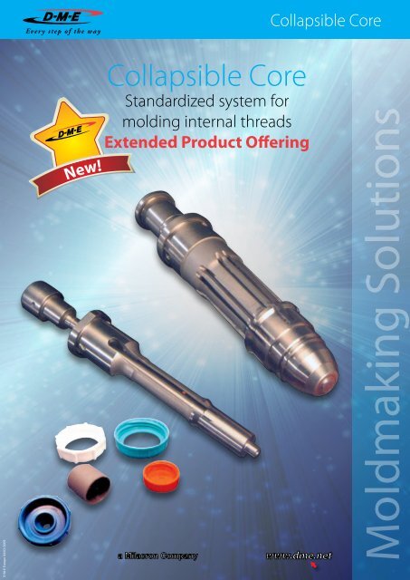
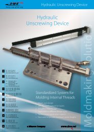
<strong>Collapsible</strong> <strong>Core</strong>D-M-E Europe 04/02/2009New!<strong>Collapsible</strong> <strong>Core</strong>Standardized system formolding internal threadsExtended Product OfferingMoldmaking Solutions
Info CCM-CCGeneral description of the <strong>Collapsible</strong> <strong>Core</strong>sIt is over 30 years since D-M-E first introduced the <strong>Collapsible</strong><strong>Core</strong> and today it still continues to be a major influence formolding plastic parts requiring internal threads, undercuts,cut-outs etc. During this time a lot of technical knowledgeand experience has been gained from many applicationstackled, some of which have been very complicated. This“Know how” has been constantly passed on to the user, eitherthrough new developments, application improvementsor suggestions for new applications. One such developmentis the new range smaller diameters which complete the seriesof <strong>Collapsible</strong> <strong>Core</strong>s. The <strong>Collapsible</strong> <strong>Core</strong>s now rangefrom 18 mm to 107 mm, for the outer diameters with thecorresponding inner diameter ranging from 16 mm to 85mm. The effective collapse ranges from 1.1 mm to 4,2 mmper side at the tip of the <strong>Core</strong>, depending on the diameterof the <strong>Core</strong>.OperationAfter cooling, the mold opens and the ejector plate assemblymoves forward as far as the stop. This causes the core sleeveto move away from the centre pin and the positive collapsedsleeve to engage, which ensures that all segments have collapsed.However, the molded part remains or hangs until thestripper plate is moved forward to eject the components.This is usually carried out by the activation of two doubleacting air cylinders mounted on the ejector plates and connectedto the stripper plate on the outside of the mold. Thestripper plate is then retracted using the two air cylindersbefore the mold is closed. When closing the mold, one has toensure that the ejector plates are returned before the mold isfully closed. This can be achieved by the use of early ejectorreturns. The core sleeve is returned to the molding positionthus preventing damage to the <strong>Collapsible</strong> <strong>Core</strong>s. When themold is fully closed the next cycle can begin. When using <strong>Collapsible</strong><strong>Core</strong>s the designer has a product which offers manyopportunities for producing many variations of molded caps.The result is a mold which functions reliably and economicallyirrespective of whether it concerns a single or multiplecavity mold. Parts with internal protrusions, dimples, interruptedthreads and cut-outs can be economically producedon a high or low volume basis. It should be noted that dueto the design of the Mini <strong>Collapsible</strong> <strong>Core</strong> only interruptedthreads and undercuts can be produced. The interruptionsconsist of three small slots with width “J” (See table), but inmost cases this does not imply any technical disadvantages.Design ProcedureThe following steps are used to determine if a part can bemolded on the Mini or Standard <strong>Collapsible</strong> <strong>Core</strong>:a) Calculate the expected actual shrinkage “S” = part Ø xshrinkage (%) “S1” = part length x shrinkage (%)b) Determine that the part minor diameter “A” is not less than“A min” (See table and Fig 1)c) Determine that the part major diameter “B” is not greaterthan “B max” (See table and Fig 1)d) Determine that thread depth or part undercut at “L”does not exceed the calculated dimension “C” (seeTable and Fig.1). The collapse available decreasesfrom the front of the core at a rate of 0,02 mm/mm.When the amount of collapse “C” of the Mini or Standard<strong>Collapsible</strong> <strong>Core</strong>s is insufficient, <strong>Collapsible</strong> <strong>Core</strong>s of thesame size but with a greater collapse can be obtained.TypeCCM-0001CCM-0002CCM-0003CC 125 PCCC 150 PCCC 175 PCCC 250 PCCK Max.1.45 mm/side1.60 mm/side1.80 mm/side0.80 mm/side1.07 mm/side1.20 mm/side1.20 mm/sidee) Determine that part depth “D” (Fig 1) doesnot exceed the value “D” given in the table.Dimension “K min” of the table must be equal to or largerthan “K min”.Material and hardnessTypeCC 252 PCCC 352 PCCC 402 PCCC 502 PCCC 602 PCCC 652 PCCC 702 PCa) The centre pin is manufactured from high quality alloysteel 1.2436, hardened to 60-65 HRC. Centre pins forStandard as well as for Mini <strong>Collapsible</strong> <strong>Core</strong>s are fittedto a specific core and cannot be interchanged. This is dueto the centre pin and core sleeve being assembled andground together.b) <strong>Core</strong> sleeves are manufactured in a 1.2363 steel (AISI01) and hardened to 55-60 HRC. All centre pins and coresleeves carry a serial number. Always verify the serialnumber prior to grinding or final assembly.c) The positive collapse sleeve is manufactured in tool steeland hardened to 55 ± 5 HRC. It is designed to functionwhen the <strong>Collapsible</strong> <strong>Core</strong> fails to collapse independentlyupon withdrawal of the centre pin. Its aim is an additionaland necessary safety factor.What materials can be molded?CK Max.1.60 mm/side2.10 mm/side2.65 mm/side3.20 mm/side3.75 mm/side4.06 mm/side4.32 mm/sideCK = Collapse per side at top of core.All commonly used thermoplastic molding resins. For manyyears filled and non-filled molding resins have been successfullymolded. Special requirements have to be taken intoconsideration when PVC is processed. When using the Minior Standard <strong>Collapsible</strong> <strong>Core</strong>s for processing this material itis recommended you contact D-M-E.www.dme.net
CCM<strong>Collapsible</strong> mini-coresMolded capShut-offCollapsingsegments (3)Non-collapsingcenter pin blades (3)Stripper platePositive collapsesleeve (included)<strong>Core</strong> sleeve with(3) collapsingsegmentsCenter pin with (3)non-collapsingbladesEjector plateassemblyCooling hole incenter pinAlignment flats on coresleeve and center pinREFA. PartMinor Ø(min.)B. PartMajor Ø(max.)C. Maximumpartundercutat LD. MaximumpartdepthE. Lengthof fittedsurfaceon coreF. Pin protrusion,min.G. Insidediametercollapsedcore nomH. Pindiameterat face(nominal)K. Stripperbushingshut-offJ. Width ofnon-collapsingR. Pin tipradiusS. MaterialshrinkageCCM 0001 10,80-S 16,38-SCCM 0002 14,22-S 20,45-SCCM 0003 18,03-S 24,51-S1,30-(0,02L+0,5S)1,45-(0,02L+0,5S)1,50-(0,02L+0,5S)21,60-S1-K 21,60 0,4 (0,8 max) 2,30 7,60 4,00 4 0,2021,60-S1-K 21,60 0,4 (0,8 max) 4,60 10,70 4,83 4 0,2025,40-S1-K 25,40 0,4 (0,8 max) 7,90 14,20 5,08 4 0,20S= Shrinkagefactor (%)x Part diameter(mm)S1= Shrinkagefactor (%)x Part length(mm)
Info CCM-CCPart design - special requirementsFor successful operation the design of the part must fulfil thefollowing requirements:a) In contrast with the Standard <strong>Collapsible</strong> <strong>Core</strong> it is not possibleto mold parts with full threads with the Mini <strong>Collapsible</strong><strong>Core</strong>. The three remaining “marks” on the part resultfrom the three interrupted areas with width “J” of the noncollapsingcentre pin blades. Make sure that the top of thecentre pin protrudes beyond the top of the core sleeve.b) The centre pin must protrude beyond the core face byat least the distance “F”. Protrusions down to “F min” areacceptable but “F max” is recommended. For “F min” and“F max” see Table or <strong>Collapsible</strong> <strong>Core</strong> dimensions leaflet.Radius “R” is most important. For “R min” and “R max” see<strong>Collapsible</strong> <strong>Core</strong> dimension drawing.c) There must be no undercuts on the face of the core segments.This will prevent the <strong>Collapsible</strong> <strong>Core</strong> from functioning.d) Undercuts on the face of the pin must not interfere withfull radial movement of the core. They must be located eitherforward of the core face or within a diameter smallerthan “G” (see Table, Fig 3; max 4 mm - see <strong>Collapsible</strong> <strong>Core</strong>dimension drawing). In no case should the undercutsbe so deep that they come close to the cooling lines inthe centre pin. For special requirements please contactD-M-E.e) The core face must have a draft of at least 3° starting nofurther than 0.8 mm from the top of the pin. A greaterdraft is desirable when “B” is near “B max” (ex. 4-5°).f) All undercuts should be drafted. A minimum draft of 5° isrequired (see Table, fig 3), more is recommended. Interruptedundercuts also require a side draft of at last 5°.g) Means must be provided for carrying the molded part offof the collapsed core at the completion of the ejectionstroke. This is normally done by providing a ring projection(0.25 x 0.25 mm) on the face of the stripper stroke. Thepart must not drag over the core (see detail Y on <strong>Collapsible</strong><strong>Core</strong> dimensions leaflet).h) As in conventional practice, sharp interior corners must beavoided to prevent stress concentration in the steel. Neverpermit a ground thread to run out through the face of thecore. This leaves a knife edge of steel that will break off intime.www.dme.net
Info CCM-CCContact us for more infoon our entire range ofmoldmaking productsNL ES FR UK SK CZDEExport BERO PLTel. : +32 15 21 50 21Fax : +32 15 40 51 21dme_benelux@dmeeu.comTel. : +32 15 21 50 17Fax : +32 15 40 51 17dme_export@dmeeu.comTel. : +49 (0)2351 437 00800 664 82 50 - Toll freeFax : +49 (0)2351 437 2200800 664 82 51 - Toll freedme_normalien@dmeeu.comTel.: 800 142 451 - 571 616 320Fax: 800 142 450 - 571 611 996dme_cz@dmeeu.comTel.: 0800 142 451 - +420 571 616 320Fax: 0800 142 450 - +420 571 611 996dme_cz@dmeeu.comTel.: +44 2071 3300 37Fax: +44 2071 3300 36dme_uk@dmeeu.comTel.: +33 1 49 93 92 23Fax: +33 1 49 93 92 22dme_france@dmeeu.comTel.: 900 900 342 - Toll freeFax: 900 900 343 - Toll freeexpulsores_girona@dmeeu.comTel. : +31 (0)2065 45 571Fax : +31 (0)2065 45 572dme_benelux@dmeeu.comMax. molded lengthincl. mold shut-off20,32 mmMax. molded lengthincl. mold shut-off21,59 mmTel. : +800 331 1312Fax : +800 331 1313dme_polska@dmeeu.comTel. : 0800 833 370 - Toll freeFax : 0800 833 371 - Toll freebogdan_nestor@dmeeu.comD-M-E Europe C.V.B.A. Industriepark Noord G1, B-2800 Mechelen , Belgium - Trade Register Mechelen, VAT BE 0456.932.455Prices in EURO per piece. Subject to change without prior notice. For conditions of sales and price info see www.dme.net.


