Download the brochure - UK EPR
Download the brochure - UK EPR
Download the brochure - UK EPR

Create successful ePaper yourself
Turn your PDF publications into a flip-book with our unique Google optimized e-Paper software.
A Generation III+ nuclear power plantThe Pathof Greatest Certainty
Readers accustomed to Anglo-Saxon units can use<strong>the</strong> following table to convert <strong>the</strong> main unitsfrom <strong>the</strong> International Metric System.1 meter (m) = 3.2808 feet= 39.370 inches1 square meter (m 2 ) = 10.764 square feet1 cubic meter (m 3 ) = 219.97 imperial gallons= 264.17 US gallons1 kilogram (kg) = 2.2046 pounds1 tonne (t) = 0.984 long ton1 bar = 14.504 psi> Conversion of temperature (°C into °F)Temp. °C x 9/5 + 32 = Temp. °F> All pressures are expressed in absolute bar.
FOREWORDThe need to secure long-term energy supplies, stabilize energy costsand combat global warming, argues in favor of a wide and diverse energymix. Against this backdrop, nuclear power, which is proving increasinglycompetitive, safe, reliable and environmentally friendly, has a vital role to play.As a world expert in energy, AREVA creates and offers solutions to generate,transmit and distribute electricity; its businesses are long-term, and cover everyarea of civil nuclear power generation to meet electricity needs.This encompasses <strong>the</strong> front end of <strong>the</strong> fuel cycle (uranium mining, conversion andenrichment, nuclear fuel fabrication), reactor design, construction, maintenanceand services, <strong>the</strong> back end of <strong>the</strong> fuel cycle (treatment, recycling, transport andlogistics, clean-up), and finally transmission and distribution of electricity from <strong>the</strong>generator to <strong>the</strong> high and medium voltage grids.The <strong>EPR</strong> reactor is AREVA’s Generation III+ PWR (Pressurized WaterReactor). It has been designed to satisfy <strong>the</strong> needs of electrical utilities for a newgeneration of nuclear power plants, offering increased levels of safety andcompetitiveness, and meeting more efficiently tomorrow’s energy requirements.The <strong>EPR</strong> reactor is already under construction in Finland, France and China,and is currently undergoing licensing or pre-licensing in <strong>the</strong> US and <strong>UK</strong>.Generation III+… we’re making it happen…I 01
The Path ofGreatest CertaintyEnergy supply certaintyThe <strong>EPR</strong> reactor is a 1,600 + MWe PWR. Its evolutionary designis based on experience from several thousand reactor-years ofoperation of Light Water Reactors worldwide, primarily thoseincorporating <strong>the</strong> most recent technologies: <strong>the</strong> N4 (Chooz B1-B2and Civaux 1-2) and KONVOI (Neckarwes<strong>the</strong>im-2, Isar-2 andEmsland) reactors currently in operation in France and Germanyrespectively. The <strong>EPR</strong> design integrates <strong>the</strong> results of decadesof research and development programs, in particular those carriedout by <strong>the</strong> CEA (French Atomic Energy Commission) and <strong>the</strong>German Karlsruhe research center. Through its N4 and KONVOIfiliation, <strong>the</strong> <strong>EPR</strong> reactor totally benefits from an uninterruptedevolutionary and innovative process; it has a proven technologybased on 87 PWRs built throughout <strong>the</strong> world.Thanks to a number of technological advances, <strong>the</strong> <strong>EPR</strong> reactoris at <strong>the</strong> forefront of nuclear power plants design. Significant continuousimprovement has been incorporated into its main features:• <strong>the</strong> reactor core and its flexibility in terms of fuel management,• <strong>the</strong> reactor protection system,• <strong>the</strong> instrumentation and control (I&C) system, <strong>the</strong> operator friendlyhuman-machine interface and computerised control room of<strong>the</strong> plant,• <strong>the</strong> large components such as <strong>the</strong> reactor pressure vesseland its internal structures, <strong>the</strong> steam generators and <strong>the</strong>primary coolant pumps.AREVA NP’s Saint-Marcel and JSPM plants (in Chalon andJeumont) have ga<strong>the</strong>red over thirty years of experience in <strong>the</strong> manufacturingof nuclear heavy components and are keeping it up todate.➡ The <strong>EPR</strong> TM design relies on a sound andproven technology.➡ Continuous in-house design andmanufacturing cooperation for a betteroptimization.➡ Design and licensing, constructionand commissioning, operability andmaintainability of <strong>EPR</strong> TM units benefit from<strong>the</strong> long lasting and worldwide experienceand expertise of AREVA.Safety first and foremostThe <strong>EPR</strong> technology offers a significantly enhanced level ofsafety: major safety systems consist of four separate subsystems,each capable of performing 100% of <strong>the</strong> safety function. Moreoverfunctional diversity ensures that in case of total loss of a safetysystem, in spite of its redundancy, <strong>the</strong> safety function can beperformed by ano<strong>the</strong>r system. In order to achieve its high level ofsafety, <strong>the</strong> <strong>EPR</strong> reactor also features major innovations, especiallyin fur<strong>the</strong>r preventing core meltdown and mitigating its potentialconsequences. The <strong>EPR</strong> design also benefits from enhancedresistance to external hazards, including aircraft crash andearthquake. Toge<strong>the</strong>r, <strong>the</strong> <strong>EPR</strong> operating and safety systemsprovide progressive responses commensurate with <strong>the</strong> potentialconsequences of abnormal occurrences.Project and licensing certaintyThe French-German cooperation set up to develop <strong>the</strong> <strong>EPR</strong>technology brought toge<strong>the</strong>r, from <strong>the</strong> start of <strong>the</strong> project:• power plant vendors, Framatome and Siemens KWU (whosenuclear activities have since been merged to form FramatomeANP, now AREVA NP),> Building on experienceEnhanced safety level and competitivenessEvolutionarydevelopmentkeeps referencesChooz B1&2, Civaux 1&2.N4Solid basis of experiencewith outstanding performanceKONVOINeckarwes<strong>the</strong>im-2, Isar-2 and Emsland.02 I
• EDF (Électricité de France) and <strong>the</strong> major German utilitiespresently grouped in E.ON, EnBW and RWE Power,• <strong>the</strong> safety authorities from both countries to harmonise safetyregulations.The <strong>EPR</strong> design takes into account <strong>the</strong> expectations of utilitiesas stated by <strong>the</strong> “European Utility Requirements” (EUR). It complieswith <strong>the</strong> specific requirements formulated by <strong>the</strong> French and Germansafety authorities for <strong>the</strong> next generation of nuclear reactors.The Finnish electricity utility Teollisuuden Voima Oy (TVO) signeda contract with <strong>the</strong> AREVA and Siemens consortium to build aturnkey <strong>EPR</strong> unit at <strong>the</strong> Olkiluoto site in Finland. The constructionpermit was obtained in February 2005.On January 23, 2007, EDF ordered AREVA’s 100 th nuclear reactor,which is being built in France, on <strong>the</strong> Flamanville site. Theconstruction permit was awarded on April 10, 2007.On November 26, 2007, AREVA and CGNPC signed a contract for<strong>the</strong> supply of two <strong>EPR</strong> Nuclear Islands on <strong>the</strong> new site of Taishanin China in <strong>the</strong> context of a long-term cooperation agreement.And on April 23, 2008, E.ON chose <strong>the</strong> <strong>EPR</strong> reactor as its referencedesign for <strong>the</strong> new NPPs in <strong>the</strong> United Kingdom.AREVA’s supply chain is integrated, comprehensive and time-tested,which confers certainty to its projects:• expertise is all within <strong>the</strong> company, at all levels,• <strong>the</strong> procurement schedule is controlled internally and <strong>the</strong>reforemore flexible,• specific customer or regulator requirements are more efficientlyaddressed.➡The <strong>EPR</strong> power plant is under constructionin Finland, France and China, andis currently undergoing licensing orpre-licensing in <strong>the</strong> US and <strong>UK</strong>.➡The integration of design and manufacturingstreng<strong>the</strong>ns AREVA’s supply chain and,as a result, project certainty.Predictable business performanceThe forthcoming generation of nuclear power plants will haveto demonstrate its competitiveness also in deregulated electricitymarkets.Thanks to an early focus on economic performance during itsdesign process, <strong>the</strong> <strong>EPR</strong> technology offers significantly reducedpower generation costs, about 20% lower than those of largecombined-cycle gas plants.This high level of competitiveness is achieved through:➡ a unit power in <strong>the</strong> 1,600 + MWe range,providing an attractive cost of <strong>the</strong> kWeinstalled,➡ a 36-37% overall efficiency dependingon site conditions (presently <strong>the</strong> highestvalue ever for water reactors),➡ a design for a 60-year service life,➡ an enhanced and more flexible fuelutilisation,➡ an availability design target above 92%.Significant advancesfor sustainable developmentThe <strong>EPR</strong> reactor due to its optimized core design and higheroverall efficiency offers many significant advantages in favor ofsustainable development, typically:• 7-15% saving on uranium consumption perproduced MWh,• 10% reduction on long-lived actinidesgeneration per MWh, through improved fuelmanagement,• 10% gain on <strong>the</strong> “electricity generation”versus “<strong>the</strong>rmal release” ratio,(compared to 1,000 MWe-class reactors).➡Energy supply certainty with <strong>the</strong>evolutionary design, operational flexibilityand shortened outages.➡Engineering certainty for customersthrough evolutionary design.➡Licensing certainty with constructionlicense obtained in France and in Finland,licensing process launched in <strong>the</strong> UnitedStates, <strong>the</strong> United Kingdom and China.➡Procurement certainty for criticalcomponents directly sourced fromAREVA’s existing integrated facilities.➡Project certainty with ongoing buildingexperience and established supply chain.➡Business performance certainty with anefficiency up to 37%, flexible fuel management,low operational maintenance costs.I 03
INTRODUCTIONIn a nuclear power plant, <strong>the</strong> reactor is <strong>the</strong> component where <strong>the</strong> heat, necessaryto produce <strong>the</strong> steam, is generated by <strong>the</strong> fission of atomic nuclei.The steam produced drives a turbine generator, which generates electricity.The nuclear steam supply system is <strong>the</strong> counterpart of <strong>the</strong> coal, gas or oil-firedboilers used in fossil-fuelled power plants.In Pressurized Water Reactors (PWR)such as <strong>the</strong> <strong>EPR</strong> power plant, ordinary(light) water is utilized to remove<strong>the</strong> heat produced inside <strong>the</strong> reactorcore by <strong>the</strong> nuclear fission phenomenon.This water also slows down (ormoderates) neutrons (<strong>the</strong> constituentsof atomic nuclei that are released in <strong>the</strong>nuclear fission process). Slowing downneutrons is necessary to sustain<strong>the</strong> nuclear reaction (neutrons must bemoderated to be able to break down<strong>the</strong> fissile atomic nuclei).The heat produced inside <strong>the</strong> reactorcore is transferred to <strong>the</strong> turbinethrough <strong>the</strong> steam generators.Only heat is exchanged between <strong>the</strong>reactor cooling circuit (primary circuit)and <strong>the</strong> steam circuit used to feed <strong>the</strong>turbine (secondary circuit). Noexchange of cooling water takes place.The primary cooling water is pumpedthrough <strong>the</strong> reactor core and <strong>the</strong> tubesinside <strong>the</strong> steam generators,in four parallel closed loops, by coolantpumps powered by electric motors.Each loop is equipped with a steamgenerator and a coolant pump.The reactor operating pressureand temperature are such that <strong>the</strong>cooling water does not boilin <strong>the</strong> primary circuit but remainsin <strong>the</strong> liquid state.A pressurizer, connected to oneof <strong>the</strong> coolant loops, is used to control<strong>the</strong> pressure in <strong>the</strong> primary circuit.PressurizerPrimarypumpSteam generatorControlrod drivemechanismReactorcoreVessel04 I
Feedwater entering <strong>the</strong> secondary sideof <strong>the</strong> steam generators absorbs <strong>the</strong>heat transferred from <strong>the</strong> primary sideand evaporates to produce saturatedsteam. The steam is mechanically driedinside <strong>the</strong> steam generators <strong>the</strong>ndelivered to <strong>the</strong> turbine. After exiting<strong>the</strong> turbine, <strong>the</strong> steam is condensedand returned as feedwater to <strong>the</strong> steamgenerators.A generator, driven by <strong>the</strong> turbine,generates electricity.Transformer➡The following chapters providea detailed explanation and descriptionof a nuclear power station basedon an <strong>EPR</strong> reactor.GeneratorHigh voltageelectrical linesFeedwaterpumpCondenserReheaterCoolingwaterPrimary systemSecondary system:– Steam– WaterI 05
TABLE OF CONTENTSpage 08<strong>EPR</strong> NUCLEAR ISLAND><strong>EPR</strong> REACTOR LAYOUT>PRIMARY SYSTEM>REACTOR CORE>SYSTEMSChemical and volume controlSafety injection/residual heat removalIn-containment refuellingwater storage tank (IRWST)Emergency feedwaterEssential Service WaterUltimate Cooling Water systemO<strong>the</strong>r safety systemsComponent Cooling WaterO<strong>the</strong>r systemsPower supplyFuel handling and storagepage 30SAFETY>NUCLEAR SAFETYThree protective barriersDefense in depth><strong>EPR</strong> SAFETY SYSTEMSDesign choices for reducing<strong>the</strong> probability of accidentsliable to cause core meltDesign choices for limiting <strong>the</strong>consequences of severe accidents>INSTRUMENTATION& CONTROL SYSTEM<strong>EPR</strong> I&C overall architectureRole of <strong>the</strong> I&C systems06 I
page 38<strong>EPR</strong> REACTOR CONSTRUCTION><strong>EPR</strong> REACTOR CONSTRUCTIONTIME SCHEDULEDesign featuresConstruction and installation methodsMajor component manufacturingCommissioning testspage 40PLANT OPERATION,MAINTENANCE & SERVICESAn availability design target above 92%A high level of operational manoeuvrabilityAn enhanced radiological protectionPlant servicespage 44ENVIRONMENTAL IMPACTDesignConstructionOperationsDecommissioningI 07
<strong>EPR</strong> REACTOR LAYOUT page 10> PRIMARY SYSTEM page 14> REACTOR CORE page 18> SYSTEMS page 20CHEMICAL AND VOLUME CONTROL page 20SAFETY INJECTION/RESIDUAL HEAT REMOVAL page 21IN-CONTAINMENT REFUELLING WATERSTORAGE TANK page 22EMERGENCY FEEDWATER page 22OTHER SAFETY SYSTEMS page 22COMPONENT COOLING WATER page 23ESSENTIAL SERVICE WATER page 23ULTIMATE COOLING WATER SYSTEM page 23OTHER SYSTEMS page 23POWER SUPPLY page 24FUEL HANDLING AND STORAGE page 25> INSTRUMENTATION& CONTROL SYSTEM page 26<strong>EPR</strong> I&C OVERALL ARCHITECTURE page 26ROLE OF THE I&C SYSTEMS page 2808 I
<strong>EPR</strong> NUCLEAR ISLANDCivaux nuclear power plant, France(N4, 1,500 MWe)I 09
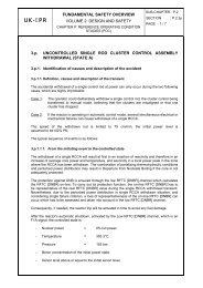
■ <strong>EPR</strong> REACTOR NUCLEAR ISLAND<strong>EPR</strong> REACTOR LAYOUT734133235461 Reactor BuildingThe Reactor Building located in <strong>the</strong> center of <strong>the</strong> Nuclear Island houses<strong>the</strong> main components of <strong>the</strong> Nuclear Steam Supply System (NSSS)as well as <strong>the</strong> In-Containment Refueling Water Storage Tank (IRWST).Its main function is to prevent <strong>the</strong> release of radioactive materials into<strong>the</strong> environment under all circumstances, including possible accidentconditions. It consists of a cylindrical pre-stressed concrete innercontainment with a metallic liner, surrounded by an outer reinforcedconcrete shell.The main steam and feedwater valves are housed in dedicatedreinforced concrete compartments adjacent to <strong>the</strong> Reactor Building.The primary system arrangement is characterized by:• a pressurizer located in a separate area,• concrete walls between <strong>the</strong> loops and between <strong>the</strong> hot and coldlegs of each loop,• a concrete wall (secondary shield wall) around <strong>the</strong> primary systemto protect <strong>the</strong> containment from missiles that could be caused by<strong>the</strong> failure of pressurized equipment, and to provide shieldingagainst radiation produced by <strong>the</strong> primary system.are separated within <strong>the</strong> building. Areas of high activity are separatedfrom areas of low activity by means of shielding facilities. The lowerpart of <strong>the</strong> building houses <strong>the</strong> fuel pool cooling system, <strong>the</strong> extraborating system, and <strong>the</strong> chemical and volume control system. Theredundant trains of <strong>the</strong>se systems are in two separate divisions of <strong>the</strong>building that are physically separated by a wall.3 The Safeguard BuildingsThe four Safeguard Buildings house key safety systems such as <strong>the</strong>Safety Injection System and <strong>the</strong> Emergency Feedwater System, and<strong>the</strong>ir support systems. These safety systems are divided into fourtrains each of which is housed in a separate division located in oneof <strong>the</strong> four Safeguard Buildings.The combined Low Head Safety Injection System and Residual HeatRemoval System is arranged in <strong>the</strong> inner radiologically controlledareas, whereas <strong>the</strong> Component Cooling and Emergency FeedwaterSystems are installed in outer areas classified as radiologicallynon-controlled. The Main Control Room is located in one of <strong>the</strong>Safeguard Buildings.2 Fuel BuildingThe Fuel Building, located on <strong>the</strong> same basemat that supports <strong>the</strong>Reactor Building and <strong>the</strong> Safeguard Buildings, houses an interimfuel storage pool for fresh and spent fuel and associated fuel handlingequipment. Operating compartments and passageways, equipmentcompartments, valve compartments and <strong>the</strong> connecting pipe ducts4 Diesel BuildingsThe two Diesel Buildings house <strong>the</strong> four emergency Diesel generators,two Station Black Out Diesel (SBO) Generators and <strong>the</strong>ir supportsystems. The SBO are used to supply electricity to <strong>the</strong> safety trainsin <strong>the</strong> event of a complete loss of electrical power. The physicalseparation of <strong>the</strong>se two buildings provides additional protection.10 I
Water outfallSwitchyardWater intakeNuclear IslandTurbine IslandBalance of PlantQuay(Typical layout - can be adjusted depending on site conditions).5 Nuclear Auxiliary Building6 Waste BuildingPart of <strong>the</strong> Nuclear Auxiliary Building (NAB) is designed as aradiologically non-controlled area in which parts of <strong>the</strong> OperationalChilled Water System are located. Special laboratories for samplingsystems are located at <strong>the</strong> lowest level. The maintenance area andsome setdown areas used during <strong>the</strong> refueling phase are arranged 7on <strong>the</strong> highest level. All air-exhausts from <strong>the</strong> radiologically controlledareas are routed, collected and controlled within <strong>the</strong> Nuclear AuxiliaryBuilding prior to release through <strong>the</strong> stack.The Waste Building is used to collect, store and treat liquid and solidradioactive waste.Turbine BuildingThe Turbine Building houses all <strong>the</strong> main components of <strong>the</strong> steamcondensate-feedwatercycle. It contains, in particular, <strong>the</strong> turbine,<strong>the</strong> generator set, <strong>the</strong> condenser and <strong>the</strong>ir auxiliary systems.I 11
■ <strong>EPR</strong> NUCLEAR ISLAND➡ The <strong>EPR</strong> reactor layout offers uniqueresistance to external hazards, especiallyearthquake and aircraft crash.• To withstand major earthquakes, <strong>the</strong>entire Nuclear Island stands on a singlethick reinforced concrete basemat.The building height has been minimisedand heavy components and water tanksare located at <strong>the</strong> lowest possible level.• To withstand <strong>the</strong> impact of a largeaircraft, <strong>the</strong> Reactor Building, Spent FuelBuilding and two of <strong>the</strong> four SafeguardBuildings are protected by an outershell made of reinforced concrete.The o<strong>the</strong>r two Safeguard Buildingsare geographically separated. Similarly,<strong>the</strong> Diesel generators are located in twogeographically separate buildings.12 I
The outer shell (in blue in <strong>the</strong> image) protects <strong>the</strong> Reactor Building, <strong>the</strong> Spent Fuel Buildingand two of <strong>the</strong> four Safeguard Buildings including <strong>the</strong> Control Room.➡ The <strong>EPR</strong> Nuclear Island design offersmajor advantages to operators, especiallyfor radiation protection and easeof maintenance.• The layout is optimized and based on <strong>the</strong>strict separation of redundant systems.• Maintenance requirements weresystematically taken into accountat <strong>the</strong> earliest stage of <strong>the</strong> design.For example, large setdown areas havebeen established to make maintenanceoperations easier for operatingpersonnel.I 13
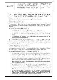
■ <strong>EPR</strong> NUCLEAR ISLANDPRIMARY SYSTEM➡PRIMARY SYSTEM CONFIGURATIONThe <strong>EPR</strong> primary system is of a well-proven 4-loop design towhich <strong>the</strong> French 1,300 MWe and 1,500 MWe N4 reactors as wellas <strong>the</strong> German KONVOI reactors belong.In each of <strong>the</strong> four loops, primary coolant leaving <strong>the</strong> reactor pressurevessel through an outlet nozzle passes into a steam generator, whichtransfers heat to <strong>the</strong> secondary circuit. The coolant <strong>the</strong>n passesthrough a reactor coolant pump before being returned to <strong>the</strong> reactorpressure vessel through an inlet nozzle. Inside <strong>the</strong> reactor pressurevessel, <strong>the</strong> coolant flows downward in <strong>the</strong> annular space between <strong>the</strong>core barrel and <strong>the</strong> vessel, <strong>the</strong>n it makes an upward U turn and flowsthrough <strong>the</strong> core to extract <strong>the</strong> heat generated by <strong>the</strong> nuclear fuel.A pressurizer, part of <strong>the</strong> primary system, is connected to one of <strong>the</strong>four loops. Its main role is to maintain <strong>the</strong> primary pressure withina specified range.The main components of <strong>the</strong> <strong>EPR</strong> reactor, reactor pressure vessel,pressurizer and steam generators are of a larger volume than similarcomponents in previous designs, providing additional operationaland safety margins.The increased free volume in <strong>the</strong> reactor pressure vessel, between<strong>the</strong> inlet/outlet nozzles and <strong>the</strong> top of <strong>the</strong> core, provides a higherwater volume above <strong>the</strong> core and thus additional time before coreuncovering in <strong>the</strong> event of a postulated loss of coolant accident. Thisgives <strong>the</strong> plant operator more time to counteract such event.This increased volume is also beneficial in shutdown conditions in <strong>the</strong>hypo<strong>the</strong>tical case of loss of <strong>the</strong> Residual Heat Removal Systemfunction.Larger water and steam phase volumes in <strong>the</strong> pressurizer smooth<strong>the</strong> response of <strong>the</strong> plant to normal and abnormal operatingtransients, allowing extended time to counteract accident situationsand an increased equipment lifetime.The larger volume of <strong>the</strong> steam generator secondary side results inan increased secondary water inventory and steam volume, whichoffers several advantages:• during normal operation, transients are smoo<strong>the</strong>r and <strong>the</strong> potentialfor unplanned reactor trips is <strong>the</strong>refore reduced;Integration of design and manufacturingCustomers benefit greatly from <strong>the</strong> fact that heavy componentdesign and manufacturing activities are broughttoge<strong>the</strong>r within <strong>the</strong> AREVA group. The possibility, uniquein <strong>the</strong> nuclear market place, of having a very close connectionbetween <strong>the</strong> two is important for project success. Thisorganisation implemented by AREVA NP since many years,is a great advantage for utilities. It provides <strong>the</strong> responsivenessneeded to achieve optimized design, manufacturing,schedule and cost to obtain <strong>the</strong> best solutions.Cattenom, France (4 x 1,300 MWe): inside a reactor building.14 I
CHARACTERISTICSDATAReactor coolant systemCore <strong>the</strong>rmal power4,590 MWth*Number of loops 4Nominal flow (best estimate) 28,315 m 3 /hReactor pressure vessel inlet temperature295.2°CReactor pressure vessel outlet temperature 330°CPrimary side design pressure176 barPrimary side operating pressure155 barSecondary sideSecondary side design pressure100 barSaturation pressure at nominal conditions (SG outlet) 77.2 barMain steam pressure at hot standby90 bar* Depending on specific customer requirements.• in hypo<strong>the</strong>tical steam generator tube rupture scenarios,<strong>the</strong> combination of a larger steam volume and <strong>the</strong> use of a setpointfor <strong>the</strong> safety valves of <strong>the</strong> steam generators above <strong>the</strong> safetyinjection pressure, prevent liquid from being released into <strong>the</strong>environment, reducing <strong>the</strong> potential for radioactivity release outside<strong>the</strong> reactor containment;• in case of a total loss of <strong>the</strong> steam generator feedwater supply, <strong>the</strong>increased mass of water in <strong>the</strong> secondary system extends <strong>the</strong> dryouttime sufficiently to enable operators to recover feedwatersupplies or to apply o<strong>the</strong>r countermeasures.In addition, <strong>the</strong> primary system design pressure has been increasedin order to reduce <strong>the</strong> actuation frequency of <strong>the</strong> safety valves, whichis also an enhancement in terms of safety.➡ The increased volume of <strong>the</strong> primarysystem is beneficial in smoothing <strong>the</strong>effects of many types of transients.➡ The primary system design pressure hasbeen increased to reduce <strong>the</strong> frequencyof safety valve actuation.➡ The management of steam generator tuberupture scenarios prevents any liquidrelease outside <strong>the</strong> reactor containment.Computer-generated imageof <strong>the</strong> <strong>EPR</strong> primary system➡ The large steam generator secondaryside water inventory increases <strong>the</strong> timeavailable to take action in case of assumedtotal loss of secondary feedwater.I 15
■ <strong>EPR</strong> NUCLEAR ISLANDThe design of <strong>the</strong> <strong>EPR</strong> components includes many improvementswith respect to previous designs. The most noteworthy aresummarized below.REACTOR PRESSURE VESSEL• The absence of penetrations through <strong>the</strong> RPV bottom headincreases its resistance in postulated core meltdown accidentsand removes <strong>the</strong> need for <strong>the</strong> corresponding in-service inspectionand potential repairs.• A reduced number of welds and improved weld geometrycompared to existing French and German 4-loop designs decrease<strong>the</strong> need for in-service inspections, facilitate non-destructiveexamination and reduce <strong>the</strong> duration of inspections.• The residual cobalt content of <strong>the</strong> stainless steel cladding isspecified at a low value of less than 0.06% to contribute to <strong>the</strong>reduction in <strong>the</strong> radiation source term.Neutron reflectorThe Neutron reflector is a stainless steel structure,surrounding <strong>the</strong> core, made of rings piled up one on top of<strong>the</strong> o<strong>the</strong>r. It is an innovative feature that gives significantbenefits:➡ by reducing <strong>the</strong> flux of neutrons escaping from <strong>the</strong> core,<strong>the</strong> reflector ensures that a greater neutron fraction isavailable to take part in <strong>the</strong> chain reaction process. Theresult is improved fuel utilisation, making it possible todecrease <strong>the</strong> fuel cycle cost;➡ by reducing <strong>the</strong> flux of neutrons escaping from <strong>the</strong> core,<strong>the</strong> reflector protects <strong>the</strong> reactor pressure vesselagainst aging and embrittlement induced by fastneutronfluence, helping to ensure <strong>the</strong> 60-year designlife of <strong>the</strong> <strong>EPR</strong> reactor pressure vessel.Reactor pressure vessel monobloc upper shell for <strong>the</strong> Olkiluoto 3 (Finland) <strong>EPR</strong> reactor pressure vessel.STANDSTILL SEAL(REACTOR COOLANT PUMP)The shaft seals are backed up with a standstill seal that closes once<strong>the</strong> pump is at rest and all seals of <strong>the</strong> leak-off lines are closed. Thestandstill seal creates a sealing surface with a metal-to-metal contactensuring <strong>the</strong> shaft tightness in case of:• simultaneous loss of water supplies from <strong>the</strong> Chemical and VolumeControl System and <strong>the</strong> Component Cooling Water System usedto cool <strong>the</strong> shaft sealing system,• cascade failure of all <strong>the</strong> stages of <strong>the</strong> shaft sealing system.This feature ensures that even in case of total station blackout orfailure of <strong>the</strong> main seals no loss of coolant would occur.16 I
AXIAL ECONOMIZER (STEAM GENERATOR)To increase <strong>the</strong> heat transfer efficiency, <strong>the</strong> axial economizer directs100% of <strong>the</strong> cold feedwater to <strong>the</strong> cold leg of <strong>the</strong> tube bundle, andabout 90% of <strong>the</strong> hot recirculated water to <strong>the</strong> hot leg. This is doneby adding a wrapper to guide <strong>the</strong> feedwater to <strong>the</strong> cold leg of <strong>the</strong>tube bundle and a partition plate to separate <strong>the</strong> cold leg from <strong>the</strong> hotleg. This design improvement increases <strong>the</strong> steam pressure by about3 bar compared to a conventional steam generator.SECTION APressure shellDouble wrapperBundle wrapperDivider plate10% recirculated water90% recirculated water100% feedwaterPressure shellDouble wrapperPRESSURIZERThe pressurizer has a larger volume to smooth <strong>the</strong> operatingtransients in order to:• ensure <strong>the</strong> equipment 60-year design life,• increase <strong>the</strong> time available to counteract an abnormal operatingsituation.Maintenance and repair (safety valves, heaters) are facilitated andradiological doses are reduced.A dedicated set of valves for depressurising <strong>the</strong> primary circuit isinstalled on <strong>the</strong> pressurizer, in addition to <strong>the</strong> usual relief and safetyvalves, to prevent <strong>the</strong> risk of high pressure core melt accident.ADivider plateHot legABundle wrapperCold legComputer-generated image of <strong>the</strong> <strong>EPR</strong> pressurizer head with its safety and relief valves.I 17
■ <strong>EPR</strong> NUCLEAR ISLANDREACTOR CORE➡The reactor core contains <strong>the</strong> fuel material in which <strong>the</strong> fissionreaction takes place, releasing energy. The reactor internalstructures support <strong>the</strong> fuel assemblies, channel <strong>the</strong> coolant andguide <strong>the</strong> control rods which control <strong>the</strong> fission reaction.The core is cooled and moderated by water at a pressure of 155 barand a temperature in <strong>the</strong> range of 300°C. The coolant containssoluble boron as a neutron absorber. The boron concentration in <strong>the</strong>coolant is varied as required to control relatively slow reactivitychanges, including <strong>the</strong> effects of fuel burnup. Additional neutronabsorbers (gadolinium), in <strong>the</strong> form of burnable absorber-bearingfuel rods, are used to adjust <strong>the</strong> initial reactivity and powerdistribution. Instrumentation is located inside and outside <strong>the</strong> core tomonitor its nuclear and <strong>the</strong>rmal-hydraulic performance and to provideinput for control functions.The main features of <strong>the</strong> core and its operating conditions have beenselected to obtain not only high <strong>the</strong>rmal efficiency of <strong>the</strong> plant andlow fuel cycle costs, but also extended flexibility for different irradiationcycle lengths and a high level of manoeuvrability.Core instrumentationThe ex-core instrumentation is used to monitor <strong>the</strong> process tocriticality and <strong>the</strong> core reactivity change, it can also measure <strong>the</strong>core power.The reference instrumentation used to monitor <strong>the</strong> power distributionin <strong>the</strong> core is an “aeroball” system. Vanadium balls are periodicallyinserted in <strong>the</strong> core. Their activation level is measured, to give valuesof <strong>the</strong> local neutron flux which are used to construct a threedimensionalpower map of <strong>the</strong> core.The fixed in-core instrumentation consists of neutron detectors and<strong>the</strong>rmocouples, that are used to measure <strong>the</strong> neutron flux distributionin <strong>the</strong> core and <strong>the</strong> temperature distribution at <strong>the</strong> core outlet.The in-core instrumentation is introduced through <strong>the</strong> vessel head.Therefore, <strong>the</strong> bottom of <strong>the</strong> reactor pressure vessel is free from anypenetration.Isar-2 unit, Germany (KONVOI, 1,300 MWe): fuel loading operation.18 I
In-core instrumentation12 lance yokes,each comprising:– 3 T.C coreoutlet– One probecontaining6 in-coredetectors– 3 or 4 aeroballprobes1 TC upperplenum89 controlassemblies4 waterlevelCHARACTERISTICSDATAReactor coreThermal power4,590 MWth*Operating pressure155 barActive fuel length4,200 mmNumber of fuel assemblies 241Number of fuel rods 63,865Average linear heat rate166.7 W/cm* Depending on specific customer requirements.Typical initial core loadingT.CGGG GG GGGGGEx-coreAeroballIn-coreGGGGGGGGGGGGG GG GGGTC: ThermocoupleGHigh enrichmentwith gadoliniumHigh enrichmentwithout gadoliniumMedium enrichmentLow enrichment➡The <strong>EPR</strong> core is characterized byconsiderable margins for fuel managementoptimization.➡Several types of fuel management (fuelcycle length, IN-OUT/OUT-IN) are availableto meet utilities’ requirements.➡The main features of <strong>the</strong> core and itsoperating conditions give competitivefuel management cycle costs.➡The <strong>EPR</strong> core also offers significantadvantages in favor of sustainabledevelopment in comparison with currentPWR designs:• 7-15% saving on uranium consumptionper produced MWh,• 10% reduction on long-lived actinidesgeneration per MWh (through improvedfuel management).I 19
■ <strong>EPR</strong> NUCLEAR ISLANDSYSTEMSCHEMICAL AND VOLUME CONTROLThe Chemical and Volume Control System (CVCS) performsseveral operational functions.• Continuous control of <strong>the</strong> water inventory in <strong>the</strong> Reactor CoolantSystem (RCS) during all normal plant operating conditions, using<strong>the</strong> charging and letdown flow.• Adjustment of <strong>the</strong> RCS boron concentration by injectingdemineralized or borated water for control of power variations andduring plant start-up or shutdown, or to compensate for coreburnup.• Ensuring <strong>the</strong> continuous monitoring of <strong>the</strong> boron concentration ofall fluids injected into <strong>the</strong> RCS, and controlling <strong>the</strong> concentrationand nature of dissolved gases in <strong>the</strong> RCS by injecting hydrogeninto <strong>the</strong> charging flow and degassing <strong>the</strong> letdown flow.• Adjustment of <strong>the</strong> RCS water chemical characteristics by injectionof chemical conditioning agents into <strong>the</strong> charging flow.• Ensuring a high flow rate capability for primary coolant chemicalcontrol, purification, treatment, degassing and storage.• Injection of cooled, purified water into <strong>the</strong> Reactor Coolant Pump(RCP) seal system to ensure cooling and leaktightness of <strong>the</strong> sealsand collection of <strong>the</strong> seal leakage flow.• Supply of borated water to <strong>the</strong> RCS up to <strong>the</strong> concentrationrequired for cold shutdown conditions for any initial condition.• Reduction of RCS pressure to Residual Heat Removal System(SIS/RHRS) operating conditions, by diverting charging flow to<strong>the</strong> auxiliary pressurizer spray nozzle to condense steam in <strong>the</strong>pressurizer.• Filling and draining of <strong>the</strong> RCS during shutdown.• Provision of pressurizer auxiliary spray, if <strong>the</strong> normal system cannotperform its function; provision of make-up to <strong>the</strong> RCS in <strong>the</strong> eventof loss of inventory due to a small leak.• Ensuring <strong>the</strong> feed and bleed function.Chemical and Volume Control SystemLetdownRegenerativeheat exchangerAuxiliary sprayCCWSHPcoolersCCWSPressure reducingstationLOOP 1PRTLOOP 2ReactorvesselCharging lineMMSamplingsystemCoolantpurificationMLOOP 4LOOP 3Seal injectionCoolantdegasificationIRWSTIRWSTGastreatmentGas wasteprocessing systemVolumecontroltankCoolantstorageBoric acidmake-upWatermake-up20 IN2H2
SAFETY INJECTION/RESIDUAL HEAT REMOVALThe Safety Injection System (SIS/RHRS) comprises <strong>the</strong> Medium HeadSafety Injection System (MHSI), <strong>the</strong> accumulators, <strong>the</strong> Low HeadSafety Injection System (LHSI) and <strong>the</strong> In-Containment RefuellingWater Storage Tank (IRWST). The system performs a dual functionbeing used both in normal operating conditions (in RHR mode) and in<strong>the</strong> event of an accident.The system is designed on <strong>the</strong> basis of a quadruple redundancy,i.e. it consists of four separate and independent trains, thus satisfying<strong>the</strong> N+2 concept (i.e. <strong>the</strong> capability of performing its function despitea single failure on one train and <strong>the</strong> unavailability of ano<strong>the</strong>r train dueto maintenance). Each train provides <strong>the</strong> capability for injection of waterinto <strong>the</strong> RCS via an accumulator, a Medium Head Safety Injection(MHSI) pump, and a Low Head Safety Injection (LHSI) pumpdischarging through a heat exchanger at <strong>the</strong> pump outlet.During normal operating conditions, operating in RHR mode, <strong>the</strong> system:• provides <strong>the</strong> capability for heat transfer from <strong>the</strong> RCS to <strong>the</strong>Component Cooling Water System (CCWS) when <strong>the</strong> RCStemperature is less than 120°C,• transfers heat continuously from <strong>the</strong> RCS or <strong>the</strong> reactor refuelingpool to <strong>the</strong> CCWS during cold shutdowns and shutdown forrefueling, as long as any fuel assemblies remain inside <strong>the</strong>containment.In <strong>the</strong> event of an assumed accident <strong>the</strong> SIS, operating in RHR modein conjunction with <strong>the</strong> CCWS and <strong>the</strong> Essential Service WaterSystem (ESWS), maintains <strong>the</strong> RCS core outlet and hot legtemperatures below 180°C following a reactor shutdown.The four redundant and independent SIS/RHRS trains are arrangedin separate divisions in <strong>the</strong> Safeguard Buildings. Each train isconnected to one dedicated RCS loop and is designed to provide<strong>the</strong> necessary injection capability required to mitigate accidentconditions. This configuration greatly simplifies <strong>the</strong> system design.The design also makes it possible to have extended periods availablefor carrying out preventive maintenance or repairs. For example,preventive maintenance can be carried out on an entire safety trainduring power operation.SI/RHR System– Four-train SIS– In-containment refuellingwater storage tank– Combined RHRS/LHSIRHRSIHot legsLHSI RHRpumpLHSI RHRpumpLHSI RHRpumpAccumulatorsAccumulatorsLHSI RHRpumpMHSIpumpMHSIpumpCold legsMHSIpumpMHSIpumpIRWSTIRWSTDivision 1 Division 2Division 3 Division 4I 21
■ <strong>EPR</strong> NUCLEAR ISLANDIn safety injection mode, <strong>the</strong> main function of <strong>the</strong> SIS is to injectwater into <strong>the</strong> reactor core following a postulated loss of coolantaccident in order to compensate for <strong>the</strong> consequence of suchevents. It is also activated following a postulated steam generatortube rupture or following <strong>the</strong> loss of <strong>the</strong> secondary-side heat removalfunction.The MHSI system injects water into <strong>the</strong> RCS at a pressure (92 barshutoff head) which prevents <strong>the</strong> system from opening <strong>the</strong> secondaryside safety valves (100 bar) following a steam generator tubeleakage. The accumulators and <strong>the</strong> LHSI system also inject waterinto <strong>the</strong> RCS cold legs when <strong>the</strong> primary pressure is sufficiently low(accumulator: 45 bar, LHSI: 21 bar shutoff head).IN-CONTAINMENT REFUELING WATERSTORAGE TANK (IRWST)The IRWST is a tank containing a large volume of borated water,which is able to collect water discharged inside <strong>the</strong> containment inpostulated accident conditions.Its main function is to supply water to <strong>the</strong> SIS, Containment HeatRemoval System (CHRS) and Chemical and Volume Control System(CVCS) pumps, and to flood <strong>the</strong> corium spreading area in <strong>the</strong> eventof a hypo<strong>the</strong>tical core melt accident.The tank is located at <strong>the</strong> bottom of <strong>the</strong> containment below <strong>the</strong>operating floor, between <strong>the</strong> reactor cavity and <strong>the</strong> radiological shield.In postulated accident conditions, <strong>the</strong> IRWST content is cooled by<strong>the</strong> LHSI system.Screens are provided to protect <strong>the</strong> SIS, CHRS and CVCS pumpsfrom debris that might become entrained with IRWST fluid underaccident conditions.EMERGENCY FEEDWATERThe Emergency Feedwater System (EFWS) is designed to ensurethat water is supplied to <strong>the</strong> steam generators when <strong>the</strong> systemsthat normally supply feedwater are unavailable.Its main safety functions are to:• transfer heat from <strong>the</strong> RCS to <strong>the</strong> secondary side via <strong>the</strong> steamgenerators, in <strong>the</strong> period before connection of <strong>the</strong> RHRS, followingany plant incidents o<strong>the</strong>r than those involving a significant breachof <strong>the</strong> reactor coolant pressure boundary; this is done inconjunction with <strong>the</strong> discharge of steam to <strong>the</strong> main condenser (ifavailable) or o<strong>the</strong>rwise via <strong>the</strong> Main Steam Relief Valves or SafetyValves;• ensure that sufficient water is supplied to <strong>the</strong> steam generatorsfollowing a loss of coolant accident or a steam generator tuberupture accident;• rapidly cool <strong>the</strong> plant down to LHSI conditions following a smallloss of coolant associated with total MHSI failure, in conjunctionwith steam release to <strong>the</strong> main condenser (if available) or o<strong>the</strong>rwisevia <strong>the</strong> Main Steam Relief Valves or Safety Valves.The system consists of four separate and independent trains, eachproviding injection capability through an emergency feed pump thattakes suction from an EFWS tank.For start-up and normal operation of <strong>the</strong> plant, a dedicated feedsystem, separate from EFWS, is provided.ESSENTIAL SERVICE WATERThe Essential Service Water System (ESWS) consists of fourseparate safety trains which cool <strong>the</strong> CCWS heat exchangers usingwater from <strong>the</strong> heat sink in all normal plant operating conditions andduring incidents and accidents.Emergency Feedwater System (EFWS)– Interconnecting headers at EFWSpump suction and dischargenormally closed.– Additional diverse electric powersupply for 2/4 trains, using two smallDiesel generator sets.EFWPEFWPMSRV1 x 50 %MSRV1 x 50 %MSSV2 x 25 %MSSV2 x 25 %MSIVMSIVTo turbineEFWPMSRV1 x 50 %MSSV2 x 25 %MSIVEFWPMSRV1 x 50 %MSSV2 x 25 %MSIVMSRV : Main Steam Relief Valves.MSSV : Main Steam Safety Valves.MSIV : Main Steam Isolation Valves.22 I
ULTIMATE COOLING WATER SYSTEMThe Ultimate Cooling Water System (UCWS) is a diverse systemallowing <strong>the</strong> dedicated cooling system associated with <strong>the</strong> mitigationof postulated severe accidents to be cooled, or to act as a back upfor cooling <strong>the</strong> fuel pool.OTHER SAFETY SYSTEMSThe Extra Borating System (EBS) ensures sufficient boration of<strong>the</strong> RCS for transfer to <strong>the</strong> safe shutdown state at a boronconcentration required for cold shutdown. This system consists oftwo separate and independent trains, each capable of injecting <strong>the</strong>total amount of concentrated boric acid required to reach <strong>the</strong> coldshutdown condition from any steady state power operating state.The Main Steam System (MSS) upstream of <strong>the</strong> Main SteamIsolation Valves is safety classified. This part consists of fourgeographically separated but identical trains, each including onemain steam isolation valve, one main steam relief valve, one mainsteam relief isolation valve and two spring-loaded main steam safetyvalves.The Main Feedwater System (MFS) upstream of <strong>the</strong> Main FeedwaterIsolation Valves is also safety classified. This consists of fourgeographically separated but identical trains, each including mainfeedwater isolation and control valves.In addition to <strong>the</strong> safety systems described above, o<strong>the</strong>r safetyfunctions are performed to mitigate postulated severe accidents,as described in <strong>the</strong> section dealing with safety and severe accidents.COMPONENT COOLING WATERThe Component Cooling Water System (CCWS) transfers heat from<strong>the</strong> safety related systems, operational auxiliary systems and o<strong>the</strong>rreactor equipment, to <strong>the</strong> heat sink via <strong>the</strong> Essential Service WaterSystem (ESWS) under all normal operating conditions.The CCWS also performs <strong>the</strong> following safety functions:• it transfers heat from <strong>the</strong> SIS/RHRS to <strong>the</strong> ESWS,• it transfers heat from <strong>the</strong> Fuel Pool Cooling System (FPCS) to <strong>the</strong>ESWS for as long as any fuel assemblies are located in <strong>the</strong> spentfuel storage pool outside <strong>the</strong> containment,• it cools <strong>the</strong> <strong>the</strong>rmal barriers of <strong>the</strong> Reactor Coolant Pump (RCP)seals,• it transfers heat from <strong>the</strong> chillers in divisions 2 and 3 and cools <strong>the</strong>Containment Heat Removal System (CHRS) via two separate trains.The CCWS consists of four separate safety trains each located inone of <strong>the</strong> four divisions of <strong>the</strong> Safeguard Buildings.OTHER SYSTEMSO<strong>the</strong>r systems include <strong>the</strong> Nuclear Sampling, Nuclear Island Ventand Drain, Steam Generator Blowdown, and Waste TreatmentSystems.• The Nuclear Sampling System is used for taking samples of gasesand liquid from systems and equipment located inside <strong>the</strong> reactorcontainment.• The Vent and Drain System collects gaseous and liquid wastefrom systems and equipment for treatment.• The Steam Generator Blowdown System prevents build-up ofsolid matter in <strong>the</strong> secondary side water.• The Waste Treatment System ensures <strong>the</strong> treatment of solid,gaseous and liquid wastes.BACK-UP FUNCTIONS AVAILABLE IN THEEVENT OF TOTAL LOSS OF THE REDUNDANTSAFETY SYSTEMS➡ The loss of secondary side heat removalis backed up by primary side feed andbleed through an appropriately designedand qualified primary system overpressureprotection system.➡ A combined function comprisingsecondary side heat removal, accumulatorinjection and <strong>the</strong> operation of <strong>the</strong> LHSISystems can replace <strong>the</strong> MHSI Systemfunction in <strong>the</strong> event of a small break lossof coolant accident.➡ Similarly, complete loss of <strong>the</strong> LHSI systemis backed up by <strong>the</strong> MHSI system andby <strong>the</strong> Containment Heat Removal System(CHRS) for IRWST cooling.SAFETY SYSTEMS AND FUNCTIONS➡ Simplification by separation of operatingand safety functions.➡ Fourfold redundancy is applied to <strong>the</strong>safety systems and to <strong>the</strong>ir supportsystems whenever maintenance duringoperation is desired. This architectureallows <strong>the</strong>m to be maintained during plantoperation, ensuring a high plant availabilityfactor.➡ The different trains of <strong>the</strong> safeguard systemsare located in four different buildings towhich strict physical separation is applied.➡ Because of <strong>the</strong> systematic applicationof functional diversity, <strong>the</strong>re is alwaysa diverse system which can perform <strong>the</strong>desired function and bring <strong>the</strong> plant backto a safe condition in <strong>the</strong> highly unlikelyevent of all <strong>the</strong> redundant trains of a systembecoming simultaneously unavailable.I 23
■ <strong>EPR</strong> NUCLEAR ISLANDPOWER SUPPLYThe outline design of <strong>the</strong> power supply system is shown below.The Emergency Power Supply is designed to ensure that <strong>the</strong>safety systems are supplied with electrical power in <strong>the</strong> eventof loss of <strong>the</strong> preferred electrical sources.The Emergency Power Supply comprises four separate andredundant trains arranged in accordance with <strong>the</strong> four divisionconcept. Each train is provided with an Emergency Diesel Generator(EDG) set.The emergency power supply system is designed to meet <strong>the</strong>requirements of <strong>the</strong> N+2 concept.The safety loads connected to <strong>the</strong> emergency power supply arethose required to safely shut down <strong>the</strong> reactor, remove residual andstored heat, and prevent <strong>the</strong> release of radioactivity.In <strong>the</strong> event of total loss of <strong>the</strong> four EDGs (Station Black Out – SBO),two additional generators, <strong>the</strong> SBO Diesel Generators, provide <strong>the</strong>power necessary to supply <strong>the</strong> emergency loads.The SBO Emergency Diesel Generators are connected to <strong>the</strong> safetybusbars of two divisions.Isar-2, Germany (KONVOI, 1,300 MWe) emergency Diesel generator.Electrical systems of an <strong>EPR</strong> nuclear power plant (typical)MaingridStand-by gridincluding auxiliarystand-bytransformerGAuxiliarynormaltransformerAuxiliarynormaltransformer10kV10kV10kV10kVMMMM690V400V690V400V690V400V690V400VTurbine IslandNuclear Island10kVEDG EDG EDG EDGG M RCP G M RCP G M RCP GRCPM10kV10kV10kVMMMMGSBO690V400V690V400V690V400V690V400VGSBO24 I
FUEL HANDLING AND STORAGEThe reactor core is periodically reloaded with fresh fuel assemblies.The spent fuel assemblies are moved to and stored in <strong>the</strong> Spent FuelPool (SFP). These operations are carried out using several handlingdevices and systems (fuel transfer tube, spent fuel crane, fuel elevator,refuelling machine and spent fuel cask transfer machine).The underwater fuel storage racks are used for underwater storage of:• fresh fuel assemblies, prior to loading,• spent fuel assemblies following fuel unloading from <strong>the</strong> core andprior to shipment off <strong>the</strong> plant.The Fuel Pool Cooling and Purification System (FPCPS) is dividedinto two subsystems: <strong>the</strong> Fuel Pool Cooling System (FPCS) and <strong>the</strong>Fuel Pool Purification System (FPPS).The FPCS provides <strong>the</strong> capability for heat removal from <strong>the</strong> SFPand is designed to keep <strong>the</strong> SFP temperature at <strong>the</strong> required levelduring normal plant operation (power operation and in refuellingoutages). This system is arranged in two separate and independenttrains with two FPCS pumps operating in parallel in each train.The FPCS also includes a third diverse cooling train to cope withany common mode failure of <strong>the</strong> two main trains (including loss of <strong>the</strong>CCWS).The FPPS comprises a purification loop for <strong>the</strong> SFP, a purificationloop for <strong>the</strong> reactor pool and <strong>the</strong> IRWST, and skimming loops for<strong>the</strong> SFP and <strong>the</strong> reactor pool. The system includes two cartridgefilters, a demineralizer and a resin trap filter used for purificationof pool water.Chooz B1, France (N4, 1,500 MWe) Fuel Building.I 25
■ <strong>EPR</strong> NUCLEAR ISLANDINSTRUMENTATION & CONTROL SYSTEMA nuclear power plant, like any o<strong>the</strong>r industrial facility, requires means for monitoring and controllingits processes and equipment. These means, as a whole, constitute <strong>the</strong> plant Instrumentation & Control (I&C)system, which comprises several subsystems with <strong>the</strong>ir electrical and electronic equipment.The I&C system is basically composed of sensors to transformphysical data into electrical signals, programmable controllersto process <strong>the</strong>se signals and provide actuator control andmonitoring and control means for use by <strong>the</strong> plant operators.The overall design of <strong>the</strong> I&C system and associated equipmentmust comply with process, nuclear safety, and operationalrequirements.➡A computerized plant I&C system,supported by modern digital technologies.<strong>EPR</strong> I&C OVERALL ARCHITECTUREWithin <strong>the</strong> overall I&C architecture, each subsystem is characterizedaccording to its functions (measurement, actuation, automation, manmachineinterface) and its role in safety or operation of <strong>the</strong> plant.A multi-level structureThe structure of <strong>the</strong> <strong>EPR</strong> Instrumentation and Control System ischaracterized by a four-level organisation:• Level 0 corresponds to sensors and actuators;• Level 1 carries out <strong>the</strong> automation functions: it comprises <strong>the</strong>reactor control and protection systems, <strong>the</strong> turbo-generator controland protection system, and <strong>the</strong> system performing all o<strong>the</strong>rautomation functions (plant control and protection);• Level 2 carries out functions related to <strong>the</strong> human-machineinterface that allow <strong>the</strong> plant to be operated and monitored;• Level 3 contains computer applications designed for non-realtimeoperation (dedicated to so-called “operating” personnel, i.e.staff carrying out operation and maintenance) and applicationsused outside of <strong>the</strong> plant. These applications provide operationaland maintenance aids (trends, reports…), which assist in off-lineanalysis of <strong>the</strong> state of <strong>the</strong> unit or equipment and interlockmanagement. They also permit interfacing and exchange of datawith offsite bodies (power distribution network dispatching, NationalEmergency Support Centers, etc.).The architecture is supported by computer aided design (CAD) and adata production organisation, which ensures <strong>the</strong> consistency of <strong>the</strong>configuration (Design CAD is used for functional studies and dataproduction CAD for <strong>the</strong> Instrumentation and Control systemsprogramming).Safety classificationI&C functions and equipment are categorized into classes depend ingon <strong>the</strong>ir importance to safety. I&C functions are implemented usingcomponents with <strong>the</strong> appropriate quality level for <strong>the</strong>ir safety class.Redundancy, separation, diversityand reliability<strong>EPR</strong> I&C systems and equipment comply with <strong>the</strong> principles ofredundancy, diversity and separation applied in <strong>the</strong> design of <strong>EPR</strong>safety-related systems. For example <strong>the</strong> Safety Injection System and<strong>the</strong> Emergency Feedwater System, which each consist of fourredundant and independent trains, also have four redundant andindependent I&C channels.Each safety-related I&C system is designed to be able tosatisfactorily fulfill its function, even if one of its channels is notavailable due to a failure and a second one is unavailable forpreventive maintenance reasons.The level of availability of <strong>the</strong> I&C systems performing safety functionsis specified so as to comply with <strong>the</strong> probabilistic safety targetsadopted in <strong>the</strong> <strong>EPR</strong> design.➡A quadruple redundant safety-related I&Cfor a fur<strong>the</strong>r increase in <strong>the</strong> level of safety.26 I
A computerized screen-based control room designed to maximize operator efficiency.Chooz B1, France (N4, 1,500 MWe).Description of <strong>the</strong> I&C architectureFunctionalsafety class*F1AF1BF2NCFunctions required in case of accident to bring <strong>the</strong>reactor to controlled state.Functions required after an accident to bring <strong>the</strong> reactorto safe state.Functions intended to avoid <strong>the</strong> risk of radioactivereleases.O<strong>the</strong>r functions contributing to plant safety (adherenceto limit operating conditions, surveillance of safety systemavailability, protection against <strong>the</strong> effects of internallygeneratedhazards, detection/monitoring of radioactivereleases, functions used in post-accident operation, etc.).Non-classified functions.* Defines Quality Assurance Requirements.I&C architecture (functional diagram)Remoteshutdown stationMain control roomMaintenancetechnical roomTechnicalsupport centerSICSSpecific I&C(TPCS, etc.)PICSinstrumentation actuators controltrip instrumentation actuatorsOperational systemsPASRCSLCRDMPACSPSSafety systemsSASSICSPICSRCSLPSSASPASPACSSafety Information& Control SystemProcess Information& Control SystemReactor Control,Surveillance andLimitation SystemProtection SystemSafety AutomationSystemProcess AutomationSystemPriority and ActuatorControl SystemControl Rod DriveCRDMMechanismTurbine ProtectionTPCS& Control SystemTXS*Diversifiedtechnology* TELEPERM-XS AREVA NP technology.XXX: safety class F1A and F1B.I 27
■<strong>EPR</strong> NUCLEAR ISLANDROLE OF THE I&C SYSTEMSLike all o<strong>the</strong>r <strong>EPR</strong> systems, <strong>the</strong> I&C systems act in accordancewith <strong>the</strong> “defense in depth” concept (see page 32).Three lines of defense are implemented:• <strong>the</strong> control system maintains plant parameters within <strong>the</strong>ir normaloperating ranges,• in case a parameter leaves its normal range, <strong>the</strong> limitation systemperforms appropriate actions to avoid <strong>the</strong> need for <strong>the</strong> initiation ofprotective actions,• if a parameter exceeds a protection threshold, <strong>the</strong> reactor protectionsystem generates <strong>the</strong> appropriate safety actions (reactor trip andsafety system actuation).Normally, to operate and monitor <strong>the</strong> plant, <strong>the</strong> operators useworkstations and a plant overview panel in <strong>the</strong> Main Control Room.In case of unavailability of <strong>the</strong> Main Control Room, <strong>the</strong> plant ismonitored and controlled from <strong>the</strong> Remote Shutdown Station.InstrumentationA number of instrumentation channels supply measured data forcontrol systems, surveillance and protection systems, and forinformation for <strong>the</strong> control room staff. Multiple-channel acquisitionis used for control of important parameters such as <strong>the</strong> pressureand temperature of <strong>the</strong> primary coolant and <strong>the</strong> liquid level in <strong>the</strong>reactor pressure vessel. Multiple-channel and diverse dataacquisition methods are implemented.Role of <strong>the</strong> various I&C subsystemsThe automation system can be broken down into two subsystems:The PAS (Process Automation System), which carries out:• automation and monitoring of <strong>the</strong> unit in normal operatingconditions. The PAS processes F2 and non-classified (NC)functions with <strong>the</strong> exception of those carried out by <strong>the</strong> RCSL(defined below) and <strong>the</strong> control and protection system for <strong>the</strong>conventional island and site-dedicated equipment;• <strong>the</strong> PAS is used for <strong>the</strong> monitoring and automation of F2 and NCfunctions to mitigate <strong>the</strong> consequences of severe accidents andmultiple failure events (risk reduction category events);• limitation actions to anticipate and avoid an eventual trip of <strong>the</strong>reactor due to a protection system threshold being exceeded.The SAS (Safety Automation System), <strong>the</strong> functions of whichare:• managing F1B post-accident processing to take <strong>the</strong> unit from <strong>the</strong>controlled state to <strong>the</strong> safe state;• preventing significant radioactive releases (F1B);• management of events which could lead to accidents or limitingaccidents.The PS (Protection System) performs <strong>the</strong> following functions:• monitoring of safety parameters in all unit operating conditions;• enabling, following an initiating event:– automatic F1A protection and safeguard actions,– automatic F1A commands of <strong>the</strong> safety support systems;• possible manual F1A actions.Diversity of equipment (software and hardware) between<strong>the</strong> PAS and <strong>the</strong> PS is implemented in order to reduce <strong>the</strong>risk of a common mode failure.The RCSL (Reactor Control Surveillance and Limitation)carries out:• monitoring of <strong>the</strong> core and <strong>the</strong> rod control function;• monitoring of <strong>the</strong> core and <strong>the</strong> reactor coolant system against <strong>the</strong>limiting conditions of operation;• limitation actions to anticipate and avoid <strong>the</strong> possibility of a reactorprotection threshold being exceeded.The PACS (Priority and Actuator Control System) manages<strong>the</strong> control and monitoring of <strong>the</strong> actuators used by both <strong>the</strong>operational and <strong>the</strong> safety systems. For actuators involved inprotection (F1A) or post-accident functions (F1B), <strong>the</strong> assignmentof priorities to commands from <strong>the</strong> PS (F1A), SAS (F1B) and/orPAS (NC/F2) is managed by <strong>the</strong> PACS.The PACS is responsible for four types of functions:• priority management;• essential protection of components;• actuator control;• actuator monitoring.Functions are allocated and distributed over several pieces ofequipment (switchgear panels and Level 1 equipment).All <strong>the</strong> I&C subsystems are implemented using digitalequipment.TELEPERM XSPS, RCSL and PACS are implemented using <strong>the</strong> TELEPERM XStechnology. TELEPERM XS is AREVA NP’s digital I&C platformspecifically developed for safety and high-reliability functions innuclear facilities. Its high functional reliability is achieved thanksto a combination of fail-safe design, fault tolerance, integratedself-checking, structural simplicity and outstanding robustness.Its resistance to environmental conditions such as temperatureswings, vibrations, seismic loadings and electromagneticradiations meets <strong>the</strong> requirements of international codesand standards (IEC, IEEE, <strong>EPR</strong>I and KTA). It is complementedby engineering tools and associated equipment supportingall design phases.In May 2000, <strong>the</strong> US Nuclear Regulatory Commission issued<strong>the</strong> generic approval for <strong>the</strong> use of <strong>the</strong> TELEPERM XS systemplatform in all safety applications, including protection systems.TELEPERM XS is also licensed and used in Argentina, Bulgaria,China, Finland, France, Germany, Hungary, Slovakia, Spain,Sweden and Switzerland.28 I
Human-machine interface (level 2)The <strong>EPR</strong> Control Room comprises:• a computerized Main Control System which allows <strong>the</strong> unitto be run in normal and accident situations. It comprises:– four operator workstations with five standardized operating screensand a dedicated screen for <strong>the</strong> operating applications (level 3),– several Compact Operator Workplaces (COW), i.e., workplaceswith a reduced number of screens which can be configured in acontrol mode or in supervision mode and used for maintenanceand outage phases;• a mimic panel in <strong>the</strong> control room which provides a commonreference for <strong>the</strong> various members of <strong>the</strong> operator team;• a Safety Information and Control System (SICS) to be usedif <strong>the</strong> Process information and Control System (PICS) is notavailable. It allows <strong>the</strong> unit to be brought to, and kept in, asafe shutdown state.In order to reduce <strong>the</strong> risk of a common mode failure, <strong>the</strong> items ofequipment used for <strong>the</strong> PICS and <strong>the</strong> SICS are independent.In <strong>the</strong> event of an unavailibility of <strong>the</strong> control room (e.g. fire), <strong>the</strong>Remote Shutdown Station (RSS), which is located outside <strong>the</strong>control room, allows operators to bring <strong>the</strong> unit to a safe state. TheRSS will be given computerized control means with technologywhich is identical to that of <strong>the</strong> PICS. The RSS comprises threeoperator stations.The architecture of <strong>the</strong> <strong>EPR</strong> Instrumentationand Control System is evolutionary with regardto existing plantsThe main developments have been in <strong>the</strong> following areas:• drawing on <strong>the</strong> lessons of <strong>the</strong> N4 series and <strong>the</strong> German KONVOIplants (architecture in four divisions, operator stations with fivestandardized screens fitted with a signalling strip for alarms,automatic limitation functions…);• increasing safety and availability of <strong>the</strong> unit (architecture infour divisions, automation of plant limits…);• optimizing performance and costs, whilst still being based onmature technological developments (proven Teleperm XScomponents, computerized mimic panel…).The <strong>EPR</strong> power plant's computerized control room features control screens providing relevant summary information on <strong>the</strong> process (computer-generated picture).I 29
SAFETY> NUCLEAR SAFETY page 31THREE PROTECTIVE BARRIERS page 31DEFENSE IN DEPTH page 32> <strong>EPR</strong> SAFETY SYSTEMS page 33Golfech 2, France (1,300 MWe):reactor pressure vessel and internals.DESIGN CHOICES FOR REDUCINGTHE PROBABILITY OF ACCIDENTS LIABLETO CAUSE CORE MELT page 33DESIGN CHOICES FOR LIMITING THECONSEQUENCES OF SEVERE ACCIDENTS page 3630 I
NUCLEAR SAFETYThe fission of atomic nuclei, which takes place in a nuclear reactor to generate heat, also producesradioactive substances from which people and <strong>the</strong> environment must be protected.Nuclear safety is <strong>the</strong> set of technical and organisational provisions that are applied in <strong>the</strong> design,construction and operation of a nuclear plant to reduce <strong>the</strong> likelihood of an accident and to limitits consequences should it never<strong>the</strong>less occur.Nuclear reactor safety requires that at all times three basicsafety functions should be fulfilled:• control of <strong>the</strong> nuclear chain reaction, and <strong>the</strong>refore of <strong>the</strong> powergenerated,• cooling of <strong>the</strong> fuel, including removal of residual heat after <strong>the</strong> chainreaction has stopped,• containment of radioactive products.Nuclear safety relies upon two main principles:• <strong>the</strong> availability of three protective barriers,• application of defense in depth.The three protective barriersTHREE PROTECTIVE BARRIERSThe concept of <strong>the</strong> “protective barriers” involves placing a series ofstrong, leak-tight physical barriers between <strong>the</strong> radioactive materialsand <strong>the</strong> environment to contain radioactivity in all circumstances:• first barrier: <strong>the</strong> fuel, inside which most of <strong>the</strong> radioactive productsare already trapped, is enclosed within a metal cladding;• second barrier: <strong>the</strong> reactor coolant system is enclosed within apressurized metal envelope that includes <strong>the</strong> reactor vessel whichhouses <strong>the</strong> core containing <strong>the</strong> fuel rods;• third barrier: <strong>the</strong> reactor coolant system is itself enclosed in a thickwalledconcrete containment building (for <strong>the</strong> <strong>EPR</strong> reactor, <strong>the</strong>containment is a double shell resting on a thick basemat, <strong>the</strong> innerwall being covered with a leak-tight metallic liner).➡Maintaining <strong>the</strong> integrity and leaktightness of just one of<strong>the</strong>se barriers is sufficient to contain radioactive fissionproducts.SteamgeneratorPressurizerReactorcoolantpumpControlrod drivemechanism321FuelassemblyReactorpressurevessel1 Fuel cladding2 Reactor coolant boundary3 Reactor containmentI 31
■SAFETYDEFENSE IN DEPTHThe concept of “defense in depth” involves ensuring <strong>the</strong>effectiveness of <strong>the</strong> protective barriers by identifying <strong>the</strong> threats to<strong>the</strong>ir integrity and by providing successive lines of defence to protect<strong>the</strong>m from failure:• first level: implementation of a safe design, high quality ofconstruction and safe and reliable operation incorporating lessonsfrom experience feedback in order to prevent occurrence of failures;• second level: means of surveillance for detecting anomalies thatcould lead to a departure from normal operating conditions, in orderto anticipate failures or to detect and intercept deviations fromnormal operational states in order to prevent anticipated operationaloccurences from escalading to accident conditions. The mostimportant of this level is <strong>the</strong> one that automatically shuts down <strong>the</strong>reactor by insertion of <strong>the</strong> control rods into <strong>the</strong> core which stops <strong>the</strong>nuclear chain reaction in a few seconds;• third level: means of action for mitigating <strong>the</strong> consequencesof failures and preventing core melt down. This level includes useof diverse and redundant systems to automatically bring <strong>the</strong> reactorto a safe shutdown state. In addition, a set of safety systems, whichalso have redundancy, are provided to ensure containment ofradioactive products;• to fur<strong>the</strong>r extend <strong>the</strong> defense in depth approach a failure of allthree levels is postulated, resulting in a “severe accident” situation.Means are provided to minimise <strong>the</strong> consequences of such asituation.➡ Applying <strong>the</strong> defense in depth conceptleads to <strong>the</strong> functions of core power andcooling control being protected by multipleredundant systems: fourfold redundancyis used in <strong>the</strong> <strong>EPR</strong> technology.➡ Safety functions are ensured by diversifiedmeans to minimize <strong>the</strong> risk of commonmode failure.➡ In addition, <strong>the</strong> components of <strong>the</strong>sesystems are designed to automaticallymove to a safe position in case of a failureor a loss of electrical or power supplies.The training for steamgenerator inspectionillustrates:➡ <strong>the</strong> first level ofdefence in depthrelating to <strong>the</strong> qualityof workmanship,➡ <strong>the</strong> second barrier,as <strong>the</strong> training relatesto steam generatortubes which form partof <strong>the</strong> primary system.Lynchburg technical center (Va, USA): training for steam generator inspection.32 I
<strong>EPR</strong> SAFETY SYSTEMSA key decision, in line with <strong>the</strong> recommendations of <strong>the</strong> French and German safety authorities,was to base <strong>the</strong> <strong>EPR</strong> design on an evolutionary approach using experience feedback from more than100 reactors previously built or under construction by AREVA NP. This decision enabled <strong>the</strong> designersto use experience from <strong>the</strong> most recently constructed plants (N4 reactors in France and KONVOIin Germany) and to avoid <strong>the</strong> risk arising from <strong>the</strong> adoption of unproven technologies.This approach did not mean that innovative solutions, backed by <strong>the</strong> results of large-scale Research andDevelopment programs, were excluded. Key innovations have been included in <strong>the</strong> <strong>EPR</strong> design to helpaccomplish <strong>EPR</strong> safety systems objectives, in particular with regard to <strong>the</strong> prevention and mitigation ofhypo<strong>the</strong>tical severe (core melt) accidents.The <strong>EPR</strong> safety approach, motivated by a desire to steadilyincrease <strong>the</strong> level of safety, involves a reinforced application of <strong>the</strong>defense in depth concept:• by improving preventive measures to reduce <strong>the</strong> probability of coremelt,• by incorporating features for limiting <strong>the</strong> consequences of coremelt accidents at <strong>the</strong> design stage.➡ A twofold safety approach is used againstsevere accidents:• reducing <strong>the</strong>ir probability by reinforcedpreventive measures,• drastically limiting <strong>the</strong>ir potentialconsequences.DESIGN CHOICES FOR REDUCING TH<strong>EPR</strong>OBABILITY OF ACCIDENTS THAT COULDCAUSE CORE MELTIn order to reduce <strong>the</strong> probability of core melt accidents, below <strong>the</strong>already extremely low levels achieved in reactors in <strong>the</strong> French andGerman nuclear power plant fleet, advances were made in threeareas:The <strong>EPR</strong> technology complies with <strong>the</strong>safety objectives set down by <strong>the</strong> Frenchand German safety authorities for futurePWR power plants:➡ fur<strong>the</strong>r reduction of core melt probability,➡ practical elimination of accidentsituations which could lead to a largeearly release of radioactive materials,➡ need for only very limited protectivemeasures in area and time*, in caseof a postulated low pressure core meltsituation.* No permanent relocation, no need for emergency evacuation outside <strong>the</strong>immediate vicinity of <strong>the</strong> plant, limited sheltering, no long-term restrictionin <strong>the</strong> consumption of food.• an extended range of operating conditions was taken into accountat <strong>the</strong> design stage,• equipment and systems were designed to reduce <strong>the</strong> likelihood ofan abnormal situation deteriorating into a severe accident,• improvements were made in <strong>the</strong> reliability of operator actions.Extension of <strong>the</strong> range of operating conditionsconsidered at design stageThe use of <strong>the</strong> probabilistic safety assessmentsAlthough <strong>the</strong> <strong>EPR</strong> safety approach is based mainly on applying <strong>the</strong>defense in depth concept (which is part of a deterministic approach),<strong>the</strong> design is supported by probabilistic analyses. These makeit possible to identify accident sequences that could cause core meltor result in large radioactivity releases, to evaluate <strong>the</strong>ir probability, andto identify <strong>the</strong>ir potential causes and countermeasures. The useof probabilistic assessment at <strong>the</strong> design phase of <strong>the</strong> <strong>EPR</strong> reactorhas been a decisive factor in <strong>the</strong> choice of technical options to improve<strong>the</strong> safety level of <strong>the</strong> reactor.For <strong>EPR</strong> technology, <strong>the</strong> probability of an accident leading to core meltis extremely small and below that in <strong>the</strong> previous-generation reactors:• below 1/100,000 (10 –5 ) per reactor/year for all types of initiating failureand hazard, which meets <strong>the</strong> objective set for new nuclear powerplants established by <strong>the</strong> International Nuclear Safety Advisory Group(INSAG) with <strong>the</strong> International Atomic Energy Agency (IAEA)– INSAG 3 report,• below 1/1,000,000 (10 –6 ) per reactor/year for events occurring inside<strong>the</strong> plant, which is a factor 10 reduction compared with <strong>the</strong> mostmodern reactors currently in operation,• below 1/10,000,000 (10 –7 ) per reactor/year for <strong>the</strong> accidentsequences associated with early loss of <strong>the</strong> radioactive containmentfunction.Consideration of shutdown states in <strong>the</strong> designof protection and safety systemsProbabilistic safety assessments highlighted <strong>the</strong> importance ofreactor shutdown states. These shutdown states were systematicallytaken into account in <strong>the</strong> <strong>EPR</strong> design, both in risk analysis and in<strong>the</strong> design of <strong>the</strong> protection and safety systems.I 33
■SAFETYGreater protection from internal and external hazardsThe layout of <strong>the</strong> safety systems and <strong>the</strong> design of <strong>the</strong> civil worksstructures minimize <strong>the</strong> risks from hazards such as earthquake,flooding, fire, airplane crash.The safety systems are designed on <strong>the</strong> basis of a quadrupleredundancy, both for <strong>the</strong>ir mechanical and electrical parts and for of<strong>the</strong> supporting I&C. This means that each system consists of foursubsystems, or “trains”, each one capable by itself of fulfilling <strong>the</strong>entire safety function. The four redundant trains are physicallyseparated from each o<strong>the</strong>r and located in four independent divisions(buildings).Each division includes one train of:• <strong>the</strong> safety injection system for injecting borated water into<strong>the</strong> reactor vessel in a loss of coolant accident. This consistsof a low-head injection system and its cooling loop, and amedium-head injection system,• <strong>the</strong> steam generator emergency feedwater system,• <strong>the</strong> electrical and I&C systems supporting <strong>the</strong>se systems.The building housing <strong>the</strong> reactor, <strong>the</strong> building in which <strong>the</strong> spent fuelis stored on an interim basis, and <strong>the</strong> four buildings correspondingto <strong>the</strong> four divisions of <strong>the</strong> safety system are provided with specialprotection against externally generated hazards such as earthquakesand explosions.Protection against an aircraft crash has been fur<strong>the</strong>r streng<strong>the</strong>ned.The reactor building is protected by a double concrete shell: an outerthick shell made of reinforced concrete and an inner thick shell madeof pre-stressed concrete which is internally covered with a thickmetallic liner. The thickness and <strong>the</strong> reinforcement of <strong>the</strong> outer shellprovide sufficient strength to absorb <strong>the</strong> impact of a large commercialaircraft. The double concrete wall is extended to <strong>the</strong> fuel building,and to two of <strong>the</strong> four safeguard buildings containing <strong>the</strong> MainControl Room and <strong>the</strong> remote shutdown station which would beused in emergency conditions.The o<strong>the</strong>r two safeguard buildings which are not protected by <strong>the</strong>double wall are remote from each o<strong>the</strong>r and separated by <strong>the</strong> reactorbuilding, which prevents <strong>the</strong>m from being simultaneously damaged.In this way, if an aircraft crash were to occur, at least three of <strong>the</strong>four trains of <strong>the</strong> safety systems would be available.1112The major safety systems comprise four sub-systems or trains, each capableof performing <strong>the</strong> entire safety function on its own. There is one train in eachof <strong>the</strong> four safeguard buildings (1) surrounding <strong>the</strong> reactor building (2) to preventa simultaneous failure of <strong>the</strong> trains.➡A set of quadruply redundant safetysystems, with independent andgeographically separated trains,minimize <strong>the</strong> consequences of potentialinternal and external hazards.➡Protection against aircraft crash isreinforced by use of a strong doublewalledconcrete shell implementedto shelter <strong>the</strong> <strong>EPR</strong> reactor.1Choice of equipment and systems to reduce<strong>the</strong> risk of an abnormal situation deterioratinginto an accidentReduction in <strong>the</strong> risk of a large reactor coolant pipe breakThe design of <strong>the</strong> reactor coolant system, <strong>the</strong> use of forged pipeworkand components, construction with high mechanical performancematerials, combined with <strong>the</strong> measures to allow early leak detectionand to facilitate in-service inspections, allow rupture of <strong>the</strong> majorreactor coolant pipework to be excluded from <strong>the</strong> design basis(i.e. to be “practically eliminated” by design).1123The outer shell (5) covers <strong>the</strong>reactor building (2), <strong>the</strong> spentfuel building (3) and two of <strong>the</strong>four safeguard buildings (1).The o<strong>the</strong>r two safeguardbuildings are separatedgeographically.45The reactor containment building has two walls:an inner pre-stressed concrete housing (4) internally covered witha metallic liner and an outer reinforced concrete shell (5).34 I
Optimized management of postulated steamgenerator tube breakSteam generator tube break could potentially result in a transfer ofwater from <strong>the</strong> primary system to <strong>the</strong> secondary system. Followingsuch an event <strong>the</strong> fall in <strong>the</strong> primary side pressure wouldautomatically induce a reactor shutdown and <strong>the</strong>n activate safetyinjection into <strong>the</strong> reactor vessel. In <strong>the</strong> <strong>EPR</strong> reactor, <strong>the</strong> drivingpressure of <strong>the</strong> medium-head injection is set below <strong>the</strong> set pressureof <strong>the</strong> secondary system safety valves, which prevents <strong>the</strong> steamgenerators from overfilling with water in <strong>the</strong>se circumstances. Thishas <strong>the</strong> advantages of avoiding <strong>the</strong> release of liquid coolant, thusreducing <strong>the</strong> potential release of radioactivity into <strong>the</strong> environment,and also considerably reducing <strong>the</strong> risk of a secondary system safetyvalve jamming in open position.Simplification of <strong>the</strong> safety systems and optimizationof <strong>the</strong>ir redundancy and diversityThose safety systems with a quadruple redundancy are spreadin four separate divisions.The system design is straightforward with minimal changes beingrequired to <strong>the</strong> system configuration whe<strong>the</strong>r <strong>the</strong> reactor is at poweror shutdown. This is illustrated by <strong>the</strong> design of <strong>the</strong> <strong>EPR</strong> safetyinjection system and residual heat removal system.The safety injection system, which would be activated in a loss ofcoolant accident, is designed to inject water into <strong>the</strong> reactor circuitto cool <strong>the</strong> reactor core. In <strong>the</strong> first phase of injection, water isinjected into <strong>the</strong> cold legs of <strong>the</strong> reactor coolant system loops(pipework sections located between <strong>the</strong> reactor coolant pumps and<strong>the</strong> reactor vessel).In <strong>the</strong> longer term, water is simultaneously injected into <strong>the</strong> cold andhot legs (legs located between <strong>the</strong> steam generators and <strong>the</strong> reactorvessel). The requirement for switching from <strong>the</strong> so-called “directinjection” phase to a “recirculation” phase in previous reactordesigns, does not apply to <strong>the</strong> <strong>EPR</strong> reactor. The <strong>EPR</strong> low headsafety injection system is provided with heat exchangers enabling itcarry out <strong>the</strong> core cooling function on its own. The <strong>EPR</strong> reactor isfur<strong>the</strong>r equipped with a dedicated system for cooling <strong>the</strong> reactorcontainment in severe accidents which would be activated by anoperator only in <strong>the</strong> event of a core melt accident.Residual heat removal is provided by <strong>the</strong> four trains of <strong>the</strong> low headpart of <strong>the</strong> safety injection system, which under <strong>the</strong>se circumstanceswould be configured to remove <strong>the</strong> residual heat in closed loop mode(suction via <strong>the</strong> hot legs, discharge into <strong>the</strong> cold legs). Safetyinjection remains available for action in <strong>the</strong> event of a leak or breakoccurring on <strong>the</strong> reactor coolant system.➡ The safety-related systems are simple,redundant and diverse to ensure highreliability and effectiveness.Increased reliability of operator actionExtension of action times available to <strong>the</strong> operatorThe short term protection and safety actions needed in <strong>the</strong> eventof an incident or accident are automated. To ensure a high levelof safety, design criteria have been established to set minimumtimeframes before operator action is required. In any case, operatoraction is not required before at least thirty minutes for actions takenin <strong>the</strong> Control Room, or one hour for actions performed locally on<strong>the</strong> plant.The increased volume of <strong>the</strong> major <strong>EPR</strong> components (reactorpressure vessel, steam generators, pressurizer) increases <strong>the</strong>response time of <strong>the</strong> reactor in upset conditions, extending <strong>the</strong>timescales available to <strong>the</strong> operators to carry out initial actions.Increased performance of <strong>the</strong> human-machine interfaceExperience feedback from <strong>the</strong> design and operation of <strong>the</strong> N4 reactors,which were among <strong>the</strong> first plants to be equipped with a fullycomputerized Control Room, and use of <strong>the</strong> last generation, yet wellproven Teleperm XS safety I&C give <strong>the</strong> <strong>EPR</strong> reactor a highperformance and reliable human-machine interface. Operator actionsare based on real time plant data made available by <strong>the</strong> state-of-<strong>the</strong>art<strong>EPR</strong> I&C.➡ Design of components, high degreeof automation, advanced design of I&Cand human-machine interface combine toincrease <strong>the</strong> reliability of operatoractions.The ergonomics of <strong>the</strong> <strong>EPR</strong> Control Room benefits from <strong>the</strong> latest developments in human-machineinterface design (computer-generated picture).I 35
■SAFETYDESIGN CHOICES FOR LIMITING THECONSEQUENCES OF SEVERE ACCIDENTS➡ A core melt-accident, in itself highlyunlikely, would only require very limitedoff-site countermeasures both with regardto time and <strong>the</strong> extent of <strong>the</strong> affected area.In response to <strong>the</strong> new safety requirements for future nuclear powerplants, introduced as early as 1993 by <strong>the</strong> French and German safetyauthorities, <strong>the</strong> plant design must be such that a core melt accidentwould need only very limited off-site countermeasures in time and space.The policy of mitigation of <strong>the</strong> consequences of a severe accident,which guided <strong>the</strong> design of <strong>the</strong> <strong>EPR</strong> reactor, <strong>the</strong>refore aimed to:➡ “practically eliminate” situations which could lead to earlyradiological releases, such as:• high-pressure core melt ejection from <strong>the</strong> reactor pressurevessel,• high-energy corium*/water interactions,• hydrogen detonations inside <strong>the</strong> reactor containment,• by-pass of <strong>the</strong> containment;➡ ensure <strong>the</strong> integrity of <strong>the</strong> reactor containment, even in <strong>the</strong>event of a low-pressure core melt followed by ex-vesselprogression, through:• retention and stabilisation of <strong>the</strong> molten corium* inside <strong>the</strong>containment,• cooling of <strong>the</strong> corium.➡ Situations which could generatea significant radioactivity release are“practically eliminated” by design.Prevention of high-pressure core meltIn addition to <strong>the</strong> reactor coolant system depressurisation systemsprovided on <strong>the</strong> o<strong>the</strong>r reactors, <strong>the</strong> <strong>EPR</strong> reactor is equipped with valvesdedicated to preventing ejection of molten core materials at high-pressurein <strong>the</strong> event of a severe accident. These valves ensure fast depressurization,even in <strong>the</strong> event of failure of pressurizer relief lines.The valves, which are controlled by <strong>the</strong> operator, are designed tosafely remain in open position after <strong>the</strong>ir first actuation. Their highreliefcapacity enables fast primary depressurisation of <strong>the</strong> reactorcoolant system to a pressure of a few bars, precluding any risk ofover-pressurization of <strong>the</strong> containment through dispersion of coriumdebris in <strong>the</strong> event of vessel failure at high pressure.Prevention of high-energycorium/water interactionThe high mechanical strength of <strong>the</strong> reactor vessel prevents it frombeing significantly damaged by any conceivable reaction, whichcould occur between corium* and coolant inside <strong>the</strong> vessel.The areas of <strong>the</strong> containment where <strong>the</strong> corium could come intocontact with water after being ejected from <strong>the</strong> pressure vessel –namely <strong>the</strong> reactor pit and <strong>the</strong> core spreading area – are kept “dry”(free of water) in most circumstances. Only when <strong>the</strong> corium isspread inside <strong>the</strong> dedicated spreading area, <strong>the</strong>n partially cooledand solidified (and <strong>the</strong>refore less reactive), is it brought into contactwith cooling water.Containment design against hydrogen risksIn <strong>the</strong> unlikely event of a severe accident, hydrogen could be releasedinside <strong>the</strong> containment in significant quantities. Hydrogen may beproduced initially by reaction between <strong>the</strong> coolant and <strong>the</strong> zirconiumused in <strong>the</strong> fuel rod cladding, and subsequently by <strong>the</strong> reactionbetween <strong>the</strong> corium and <strong>the</strong> concrete in <strong>the</strong> corium spreading andcooling area.For this reason, <strong>the</strong> pre-stressed concrete inner shell of <strong>the</strong>containment is designed to withstand pressures that couldconceivably result from <strong>the</strong> combustion of this hydrogen. Fur<strong>the</strong>rdevices called catalytic hydrogen recombiners are installed inside<strong>the</strong> containment to keep <strong>the</strong> average concentration below 10% at alltimes, to avoid <strong>the</strong> risk of detonation. Assuming hydrogen combustionby deflagration only, <strong>the</strong> pressure in <strong>the</strong> containment will not exceed5.5 bar.Corium retention and stabilization to protect<strong>the</strong> basematThe reactor pit is designed to collect <strong>the</strong> corium in <strong>the</strong> case of exvesselmelt progression and to transfer it to <strong>the</strong> corium spreadingand cooling area. The floor of <strong>the</strong> reactor pit is protected by“sacrificial” concrete which is backed-up by a protective layerconsisting of refractory concrete.* Corium: product resulting from <strong>the</strong> melting of <strong>the</strong> core components and interactionwith <strong>the</strong> structures it could meet.➡ Even in <strong>the</strong> extremely unlikely eventof a core melt accident resulting inejection of molten materials from <strong>the</strong>reactor pressure vessel, <strong>the</strong> moltencore and radioactive products wouldbe most likely to remain confinedinside <strong>the</strong> reactor building whoselong term integrity would bemaintained.In <strong>the</strong> event of core meltdown, molten core escaping from <strong>the</strong> reactor vessel would be passivelycollected and retained, <strong>the</strong>n cooled in a specific area inside <strong>the</strong> reactor building.36 I
The dedicated corium spreading and cooling area (core-catcher)consists of a channelled metal structure covered with “sacrificial”concrete. Its purpose is to protect <strong>the</strong> nuclear island basemat fromdamage. Its lower section contains cooling channels in which wateris circulated. The large spreading surface area (170 m 2 ) promotescooling of <strong>the</strong> corium.The transfer of <strong>the</strong> corium from <strong>the</strong> reactor pit to <strong>the</strong> spreading areais initiated by a passive device: a steel “plug” that melts due to <strong>the</strong>heat from <strong>the</strong> corium.After spreading, flooding of <strong>the</strong> corium is triggered by opening of apassively activated valve. It is <strong>the</strong>n cooled, also passively, by gravityinjection of water from <strong>the</strong> refuelling water storage tank located inside<strong>the</strong> containment and evaporation.The cooling stabilises <strong>the</strong> corium in a few hours and ensures itscomplete solidification in a few days.Containment heat removal systemand long-term residual heat removal deviceIn order to maintain <strong>the</strong> long-term integrity of <strong>the</strong> containment in asevere accident means are provided to control <strong>the</strong> pressure increaseinside <strong>the</strong> containment due to residual heat. A dedicated dual-trainspray system with heat-exchangers and dedicated heat sink isprovided to fulfil this cooling function. Owing to <strong>the</strong> <strong>the</strong>rmal inertia of<strong>the</strong> containment and its internal concrete structures, a long timeperiod is available for <strong>the</strong> deployment of this system by <strong>the</strong> operators(at least 12 hours) while <strong>the</strong> large containment free volume helps tolimit <strong>the</strong> pressure increase after <strong>the</strong> accident.A second mode of operation of <strong>the</strong> containment heat removal systemenables it to feed water directly into <strong>the</strong> core-catcher to cool it.Collection of inter-containment leaksIn <strong>the</strong> event of a core melt leading to vessel failure, <strong>the</strong> containmentbuilding would be <strong>the</strong> only remaining barrier of <strong>the</strong> three containmentbarriers; provisions are <strong>the</strong>refore made to ensure that it remainsundamaged and leak-tight. For <strong>the</strong> <strong>EPR</strong> technology, <strong>the</strong> followingmeasures are adopted:• a metal liner internally covers <strong>the</strong> pre-stressed concrete inner shell,• <strong>the</strong> internal containment penetrations are equipped with redundantisolation valves and leak recovery devices to avoid containmentbypass,• <strong>the</strong> architecture of <strong>the</strong> peripheral buildings and <strong>the</strong> sealing systemsof <strong>the</strong> penetrations removes <strong>the</strong> risk of direct leakage from <strong>the</strong> innercontainment to <strong>the</strong> environment,• <strong>the</strong> inter-space between <strong>the</strong> inner and outer shells of <strong>the</strong>containment is maintained at a slightly negative pressure to enableleaks from <strong>the</strong> inner containment to be collected,• <strong>the</strong> above provisions are supplemented by a containment ventilationsystem and a filter system upstream of <strong>the</strong> stack.Containment heat removalsystemContainment spraysystemRecirculation andcoolant heat exchangerSpray nozzlesWater injectioninto <strong>the</strong> corecatcherxxPassivefloodingdevicexCHRS(2x)Coriumspreading areaIn-containment refuelingwater storage tankMelt flooding via cooling deviceand lateral gapxWater level in case of waterinjection into spreading areaFL Flow limiterTwo fully redundant trains with specific diversified heat sinkI 37
<strong>EPR</strong> REACTORCONSTRUCTION> <strong>EPR</strong> REACTOR CONSTRUCTION TIME SCHEDULE page 39DESIGN FEATURES page 39Olkiluoto 3 nuclear power plant,Finland June 2009.CONSTRUCTION AND INSTALLATION METHODS page 39MAJOR COMPONENT MANUFACTURING page 39COMMISSIONING TESTS page 3938 I
<strong>EPR</strong> REACTOR CONSTRUCTION TIMESCHEDULEThe evolutionary approach adopted for <strong>the</strong> <strong>EPR</strong> design enables its construction schedule to benefitfrom <strong>the</strong> extensive construction experience feedback and <strong>the</strong> continuous improvements in processes,methodologies and tasks sequencing achieved by AREVA NP worldwide.Provisions have been made in <strong>the</strong> design, construction, and commissioning methods used to shorten<strong>the</strong> <strong>EPR</strong> reactor construction schedule as far as possible. Significant examples are as follows.DESIGN FEATURESThe general design layout of <strong>the</strong> main safety systems in four trainshoused in four separate buildings allows parallel installation worksand, later, parallel testing of individual systems.Location of electromechanical equipment lower levels means thatits installation can start early and consequently remove it from criticalpath, which contributes to <strong>the</strong> shortening of <strong>the</strong> constructionschedule.CONSTRUCTION AND INSTALLATION METHODSThree main principles are applied to <strong>EPR</strong> reactor construction andinstallation: minimization of <strong>the</strong> interfaces between civil works and installationof mechanical components, modularisation and piping prefabrication.Minimization of <strong>the</strong> interfaces between civil works and installation.The continuing search for optimisation of <strong>the</strong> interfaces between civiland installation works results in <strong>the</strong> implementation of a constructionmethodology “per level” or “grouped levels”. This enables equipmentand system installation work at level “N”, finishing construction work atlevel “N+1” and main construction work at levels “N+2” and “N+3” tobe carried out simultaneously. The methodology is used for all <strong>the</strong>different buildings except for <strong>the</strong> Reactor Building, where it cannot apply.Use of modularization for overall schedule optimization. Modularizationtechniques are considered systematically, but retained only in cases where<strong>the</strong>y offer a real benefit to <strong>the</strong> optimization of <strong>the</strong> overall constructionschedule without introducing a technical and financial burden due toadvanced detailed design, procurement or prefabrication. This approachenables <strong>the</strong> site preparation schedule to be optimized, delays investmentcosts with regard to start of operation, and so offers financial savings.For instance, modules are implemented for <strong>the</strong> civil works associatedwith <strong>the</strong> reactor building (e.g. containment liner & dome), pool structurefor vertical walls in Reactor & Fuel buildings, control room, as <strong>the</strong>y are on<strong>the</strong> critical path.Maximization of piping and support prefabrication. Piping and supportprefabrication is maximized in order to minimize installation man-hoursand especially welding and controls at installation locations; this measurealso results in an even better quality of <strong>the</strong> piping spools at lower cost.COMMISSIONING TESTSAs with <strong>the</strong> interfaces between civil and construction works, <strong>the</strong>interfaces between construction and testing have been carefullyreviewed and optimized. For instance, teams responsible for <strong>the</strong>commissioning tests are also involved in <strong>the</strong> finishing operations,flushing, and system conformance checks, so that <strong>the</strong>se activitiesare only carried out once.Instrumentation & Control factory acceptance tests are carried outon a single test platform with all cabinets interconnected, whichensures a shorter on-site test period toge<strong>the</strong>r with improved overallquality.The benefits drawn from <strong>the</strong> unique experience feedback gained byAREVA NP in previous projects, and systematic optimisation ofconstruction and testing activities and <strong>the</strong>ir interfaces, results in anoptimal technical and economical construction schedule for<strong>EPR</strong> reactor implementation. This experience and that from current<strong>EPR</strong> reactor projects, gives confidence that <strong>the</strong> planned <strong>EPR</strong>reactor time schedule is realistic.Indicative planning and overall time-scaleThe overall construction schedule of a unit in <strong>the</strong> series dependslargely on site conditions, industrial organisation and policies, andlocal working conditions. Therefore figures quoted for a specificproject cannot usually be extended to o<strong>the</strong>rs.<strong>EPR</strong> REACTOR TIME SCHEDULEMain contractEngineeringYear 0 Year 1 Year 2 Year 3 Year 4First concrete pouringStart fuel loadingCommercial operationsMAJOR COMPONENT MANUFACTURINGAREVA NP’s Chalon/Saint-Marcel and Jeumont plants have overthirty years of experience in <strong>the</strong> manufacture of heavy nuclearcomponents. This has resulted in considerable experience inoptimization of <strong>the</strong> production time of heavy nuclear components.The construction of <strong>the</strong> <strong>EPR</strong> reactor benefits from this uniquemanufacturing capability and expertise.ManufacturingLicensingCivil worksInstallationStart-up testsI 39
PLANT OPERATION,MAINTENANCE& SERVICESAN AVAILABILITY DESIGN TARGETABOVE 92% page 41Neckarwes<strong>the</strong>im nuclear power plant (Germany):unit 2 (right foreground) is of <strong>the</strong> KONVOI type(1,300 MWe).A HIGH LEVEL OF OPERATIONALMANOEUVRABILITY page 42AN ENHANCED RADIOLOGICALPROTECTION page 42PLANT SERVICES page 4340 I
PLANT OPERATION, MAINTENANCE& SERVICESPlant operators worldwide are trying hard to increase plant availability and to reduce maintenance costs.The <strong>EPR</strong> systems and components have been designed from <strong>the</strong> beginning to help <strong>the</strong>m achieve <strong>the</strong>segoals through efficient refueling outages and simplified inspection and maintenance.AN AVAILABILITY DESIGN TARGETABOVE 92%The <strong>EPR</strong> reactor is designed to exceed an availability rate of 92%.This is made possible by long cycles, short-scheduled outages forfuel loading/unloading and in-service inspections and maintenance,and also through reduced downtimes attributable to unscheduledoutages.The quadruple redundancy of <strong>the</strong> safety systems allows a part of <strong>the</strong>preventive maintenance operations to be performed while <strong>the</strong> reactoris at power.Moreover, <strong>the</strong> reactor building is designed to keep some areasaccessible, under standard safety and radiation protectionconditions, while <strong>the</strong> reactor is at power. This enables <strong>the</strong> outageand maintenance operations to be prepared and demobilized with noloss of availability. This possibility of access with <strong>the</strong> reactor on linealso facilitates field services which could be needed outsidescheduled outage periods. Based on experience feedback, easieraccess to <strong>the</strong> components of <strong>the</strong> reactor allow simple and rapidperformance of inspection and maintenance work.Access to <strong>the</strong> reactor building during power operation allows to startpreventive maintenance and outage preparation up to seven daysbefore reactor shutdown and to continue <strong>the</strong>ir demobilization up tothree days after reactor restart.The duration of <strong>the</strong> plant shutdown phase is reduced by a time gainfor reactor coolant system cooldown, depressurization and vesselhead opening. Similarly <strong>the</strong> length of <strong>the</strong> restart phase is reducedas well and benefits from <strong>the</strong> reduction in <strong>the</strong> time needed to run<strong>the</strong> beginning-of-cycle core physics tests (gain supplied by <strong>the</strong>“aeroball” in-core instrumentation system). Durations of about70 and 90 hours are respectively scheduled for <strong>the</strong> shutdown andrestart phases. For <strong>the</strong> fuel loading/unloading operations, a timeperiod below 100 hours is scheduled.➡ Typical outage duration: <strong>the</strong> duration of a regular outagefor preventive maintenance and refueling is reduced to 16 days.Duration of an outage for refueling only does not exceed11 days. Decennial outages for main equipment in-serviceinspection, turbine overhaul and containment pressure test areplanned to last 40 days.Chooz B1, France (N4, 1,500 MWe): removal of <strong>the</strong> hydraulic section of a reactor coolantpump for maintenance.The <strong>EPR</strong> reactor is designed to:➡ maximize plant availability andmanoeuvrability,➡ ease operation and maintenanceand reduce <strong>the</strong>ir costs,➡ enhance radiological protectionof <strong>the</strong> personnel,➡ protect <strong>the</strong> environment and contributeto a sustainable development.41 I I 41
- PLANT OPERATION, MAINTENANCE & SERVICESA HIGH LEVEL OF OPERATIONALMANOEUVRABILITYIn terms of operation, <strong>the</strong> <strong>EPR</strong> reactor is designed to offer <strong>the</strong>utilities a high level of manoeuvrability. It has <strong>the</strong> capacity tobe permanently operated at any power level between 25 and100% of its nominal power in a fully automatic way, with <strong>the</strong>primary and secondary frequency controls in operation.The <strong>EPR</strong> reactor capability regarding manoeuvrability is aparticularly well adapted response to scheduled and unscheduledpower grid demands for load variations, managing of gridperturbations or mitigation of grid failures.AN ENHANCED RADIOLOGICALPROTECTIONAllowance for operating constraints and for <strong>the</strong> human factor, with <strong>the</strong>aim of improving worker radiation protection and limiting radioactivereleases, toge<strong>the</strong>r with radwaste quantity and activity, was a setobjective as soon as <strong>EPR</strong> design got underway. For this purpose,<strong>the</strong> designers drew heavily upon <strong>the</strong> experience feedback from<strong>the</strong> operation of <strong>the</strong> French and German nuclear power plant fleets.Accordingly, major progress has been made, particularly in <strong>the</strong>following areas:• <strong>the</strong> choice of materials, for example <strong>the</strong> optimization of <strong>the</strong> quantityand location of <strong>the</strong> Cobalt-containing materials and liners, in orderto obtain a gain on <strong>the</strong> Cobalt 60 “source term”,• <strong>the</strong> choices regarding <strong>the</strong> design and layout of <strong>the</strong> componentsand systems liable to convey radioactivity, taking into account <strong>the</strong>various plant operating states,• <strong>the</strong> optimization of <strong>the</strong> radiation shielding thicknesses in responseto forecast reactor maintenance during outages or in service.Thanks to <strong>the</strong>se significant advances and to shorter outages,collective doses less than 0.4 Man.Sievert per reactor/year canbe expected for operation and maintenance staff (to date, for <strong>the</strong>major nuclear power plant fleets of OECD countries like France,Germany, <strong>the</strong> United States and Japan, <strong>the</strong> average collective doseobserved is about 1 Man.Sievert per reactor/year).In-service inspection machine for ultrasonic testing of reactor pressure vessels.42 I
PLANT SERVICESOptimization of plant processes and implementation of innovativemaintenance technologies and concepts are also significantcontributors to <strong>the</strong> achieving of operators’ cost and availabilityobjectives. In this area, AREVA NP supplies <strong>the</strong> most comprehensiverange of nuclear services and technologies in <strong>the</strong> world.Thanks to its experience from designing and constructing over 100nuclear power plants worldwide, its global network of maintenanceand services centers with highly trained teams (more than 4,000specialists mainly based in France, Germany and <strong>the</strong> USA) committedto excellence, AREVA NP provides a full range of inspection, repairand maintenance services for all types of nuclear power plants, basedon <strong>the</strong> most advanced techniques available today. Its field of expertisecovers <strong>the</strong> whole scope of customers’ needs from unique one-of-akindassignments to <strong>the</strong> implementation of integrated service packageswith a view to reducing outage duration. In addition, AREVA isintroducing innovative partnership models featuring long-termperformance-based contracts for services.AREVA NP’s offer of power plant services encompasses:• in-service inspection and non destructive testing,• outage services,• asset management,• life cycle management,• predictive maintenance,• supply of spare parts,• off-site maintenance of components in “hot” workshops,• fuel inspection, repair and management,• services in <strong>the</strong> fields of instrumentation and diagnosis, I & C andelectrical systems, chemistry,• plant decommissioning and waste management,• training of operating personnel,• expert consultancy.The “FROG” Owners Group (see page below) offers member electricitycompanies a cost-effective means for exchange of information andexperience. FROG’s members have access to broad operational andmaintenance feedback. They also benefit from <strong>the</strong> results of studyprograms jointly decided to deal with issues of shared interest.THE “FROG” OWNERS GROUPThe FROG (formely Framatome Owners Group)is dedicated to building strong and efficient teamingfor mutual cooperation, assistance and sharingof its members’ experience and expertise, to support<strong>the</strong> safe, reliable, cost-effective operation of its members’nuclear power units.The FROG was set up in October 1991 by five utilitycompanies that were ei<strong>the</strong>r operating or building nuclearpower plant units incorporating a Framatome nuclearsteam supply system or nuclear island.These utility companies are Electrabel from Belgium,Electricité de France, Eskom from <strong>the</strong> Republic of SouthAfrica, GNPJVC from <strong>the</strong> People’s Republic of Chinaand KHNP from <strong>the</strong> Republic of Korea.Later on, Ringhals AB from Sweden (in June 1997), LANPC,owner of <strong>the</strong> Ling Ao plant in China (in October 2000),British Energy owner of Sizewell B in <strong>the</strong> United Kingdom(in October 2002) joined <strong>the</strong> FROG as members. In 2003,GNPJVC and LANPC merged operation of <strong>the</strong>ir plants inone company DNMC.The Owners group provides a forum for its members to share<strong>the</strong>ir experiences in all domains of nuclear power plantoperation, enabling a cost-effective exchange of informationto identify and solve common issues or problems.Several working groups and technical committees areactively dealing with specific technical and managementissues. Among <strong>the</strong>m, a specific Steam Generator TechnicalCommittee, has been formed by utilities having steamgenerators served by AREVA NP. Committee participantsare <strong>the</strong> FROG members plus <strong>the</strong> companies NSP andAmerenUE from <strong>the</strong> USA, NOK from Switzerland and NEKfrom Slovenia.I 43
ENVIRONMENTALIMPACT> ENVIRONMENTAL IMPACTDESIGN page 45Saint-Alban nuclear power plant, France (1,300 MWe x 2).CONSTRUCTION page 45OPERATIONS page 45DECOMMISSIONING page 4744 I
ENVIRONMENTAL IMPACTEnsuring that <strong>the</strong> impact of a nuclear unit on <strong>the</strong> environment is minimal requires complementary actionsby <strong>the</strong> reactor vendor, <strong>the</strong> operator, <strong>the</strong> safety authorities and various o<strong>the</strong>r organizations. The vendor’scontribution to minimizing <strong>the</strong> environmental impact is set out below.DESIGNAs already stated in <strong>the</strong> section on “<strong>EPR</strong> safety systems”, <strong>the</strong>reactor has been designed to avoid <strong>the</strong> occurrence of incidents andaccidents and to reduce <strong>the</strong>ir consequences for <strong>the</strong> plant and <strong>the</strong>environment if <strong>the</strong>y were to occur.The improved <strong>the</strong>rmodynamic efficiency of <strong>the</strong> plant ensures that itscooling water requirements are minimized.The high performance core of <strong>the</strong> <strong>EPR</strong> reactor (see section on <strong>the</strong>reactor core) gives <strong>the</strong> operator increased flexibility in <strong>the</strong> utilizationof nuclear fuel to generate power. Depending on <strong>the</strong> fuelmanagement strategy adopted and on <strong>the</strong> relevant point ofcomparison, <strong>the</strong> savings on uranium consumption per unit of energyproduced can reach 7 to 15%, giving a corresponding reduction in<strong>the</strong> quantities of high-level waste.Processes have been optimized to reduce quantities of radioactiveand chemical waste through <strong>the</strong> use of <strong>the</strong> best tried and testedmethods available at an acceptable cost.CONSTRUCTIONDuring <strong>the</strong> building phase, activities such as clearance of <strong>the</strong> site,excavation, drilling, concrete production and start-up tests have apotential impact on <strong>the</strong> environment. Therefore <strong>the</strong> marine andterrestrial environments, freshwater, air, climate, landscape and <strong>the</strong>noise level must be kept under close scrutiny in order to minimizepossible consequences.OPERATIONSThe impact of operations on <strong>the</strong> environment translates into <strong>the</strong>gaseous and liquid releases, and solid wastes produced. Theevolutionary character of <strong>the</strong> <strong>EPR</strong> design makes it possible to drawbenefit from lessons learned from many years of operation of earliergeneration reactors, meaning that whenever possible, releases andwaste are reduced and, when this is not possible, <strong>the</strong> extent andimpact of such releases can be accurately predicted.Gaseous radioactive waste from an <strong>EPR</strong> reactor arises from:• <strong>the</strong> ventilation of <strong>the</strong> nuclear buildings;• <strong>the</strong> degassing of radioactive fluids.Depending on its origin, <strong>the</strong> gaseous radioactive waste is:• ei<strong>the</strong>r filtered (1) and released into <strong>the</strong> atmosphere via <strong>the</strong> dischargestack. This is generally <strong>the</strong> case for gaseous waste coming fromventilation circuits;• or retained in <strong>the</strong> treatment system to reduce <strong>the</strong> level ofradioactivity and <strong>the</strong>n filtered and released into <strong>the</strong> atmosphere via<strong>the</strong> discharge stack. This is <strong>the</strong> case for gases released by <strong>the</strong>degassing of primary cooling water.In all circumstances, gaseous releases are controlled and monitoredat <strong>the</strong> stack in order to check that <strong>the</strong>se discharges do not have anoticeable impact on <strong>the</strong> terrestrial environment.(1) Filtration allows retention of more than 99% of aerosols and iodines and <strong>the</strong>irconversion into solid waste.A concern having a bearing on <strong>the</strong> wholelife cycle of <strong>the</strong> plant.Saint-Alban nuclear power plant, France (1,300 MWe x 2).Protection of <strong>the</strong> public and of <strong>the</strong>environment requires optimization ateach step of <strong>the</strong> <strong>EPR</strong> life cycle of:➡design;➡construction;➡operation;➡dismantling and decommissioning.I 45
■ENVIRONMENTAL IMPACTLiquid radioactive waste is placed in two categories dependingon its origin:• waste from <strong>the</strong> primary system, which contains activation products(cobalt, manganese, tritium, carbon-14, etc.) minor quantities ofdissolved fission gases (xenon, iodine, etc.), fission products(caesium, etc.), and also chemical substances such as boric acidand lithium hydroxide. The chemical substances can be recycled;• waste from <strong>the</strong> systems connected to <strong>the</strong> primary system, whichmakes up <strong>the</strong> rest of <strong>the</strong> effluents. Among <strong>the</strong>se, <strong>the</strong>re are:– effluents which are radioactive and free from chemical pollution,– radioactive and chemically charged effluents, effluents with a verylow level of radioactivity collected by <strong>the</strong> floor drains (2) .After being systematically collected, this waste is treated to retainmost of its radioactivity. It is <strong>the</strong>n channelled to storage tanks where itundergoes both radioactive and chemical testing before beingdisposed of.Solid radioactive wasteReduction in <strong>the</strong> volume of solid radioactive waste to lessen <strong>the</strong>unit’s impact on <strong>the</strong> environment was one of <strong>the</strong> objectives adoptedat <strong>the</strong> design stage.Spent fuel is removed for ei<strong>the</strong>r reprocessing or storage and residualwaste created is packaged, to ensure that radioactive matter isconfined, in glass representing once conditioned 5 m 3 per yearof high activity long-lived (3) waste and in concrete packagesrepresenting once conditioned 4 m 3 per year of long-livedintermediate level waste.The production of operating waste is limited to 80 m 3 per year perunit thanks to <strong>the</strong> materials chosen to build <strong>the</strong> reactor and,<strong>the</strong> zoning (4) of premises after start-up to reduce <strong>the</strong> possiblecontamination of conventional equipment by radioactive material.Short-lived low level waste, a by-product of <strong>the</strong> operating process,is sorted, treated and stored in <strong>the</strong> <strong>EPR</strong> unit’s Radioactive WasteProcessing Building so as to reduce <strong>the</strong> volume of waste as muchas possible (compaction) and to ensure <strong>the</strong> radioactive material isconfined through suitable packing.(2) The floor drains constitute a network of underground pipes which collectmaterial leaks, water from drainage operations, and water used to wash <strong>the</strong> floors.(3) Lifetime of a radioactive substance depends on its radioactive half-life period,which is <strong>the</strong> time after which its activity has reduced by a half because of <strong>the</strong>natural decrease of <strong>the</strong> radioactive source.(4) Separation of zones presenting contamination risks from o<strong>the</strong>r zones by meansof doors, chambers, etc.Typical distribution of annual doseto population from all sourcesSand sampling in <strong>the</strong> Cotentin peninsula (Flamanville and La Hague area).63% radon, soil and terrestrial materials15% medical12% background radiation (sun and Milky Way)9.5% human body0.49% miscellaneous artificial sources0.01% nuclear power plants46 I
Chemical wasteOperating a nuclear power station also involves <strong>the</strong> discharge ofliquid chemical waste and gaseous emissions. These wastes areprocessed, tested and monitored to ensure that <strong>the</strong>ir discharge is incompliance with authorized limits.Conventional wasteConventional waste produced during <strong>the</strong> operating stage is alsosubjected to a strict management procedure so as to reduce itsvolume. It is sorted and stored in an adapted temporary location on<strong>the</strong> site.Waste produced during <strong>the</strong> construction phase is treated in <strong>the</strong>same manner as during <strong>the</strong> operating phase, in a temporary locationspecifically created on <strong>the</strong> building site. The materials extractedduring <strong>the</strong> earth-moving works, excavated material and rocks, arereused as much as possible on <strong>the</strong> site as fill and in <strong>the</strong> making ofconcrete after crushing.DECOMMISSIONINGOn <strong>the</strong> basis of <strong>the</strong> experience feedback resulting from dismantlingoperations performed in various countries on first generation nuclearpower plants, <strong>the</strong> <strong>EPR</strong> unit’s design includes various measureswhich:• minimize <strong>the</strong> volume of radioactive structures,• reduce <strong>the</strong> potential hazard of <strong>the</strong> waste, for instance with <strong>the</strong>material choice minimizing hazardous substances,• lower <strong>the</strong> irradiation level of components submitted to fuel radiation,• restrict <strong>the</strong> spread of contamination and favor systemsdecontamination, for example with <strong>the</strong> implementation of aradiological zoning,• facilitate <strong>the</strong> access of personnel and machines and <strong>the</strong> evacuationof waste, for instance with <strong>the</strong> implementation of suitable areasand openings,• ensure <strong>the</strong> ga<strong>the</strong>ring of building and operating data needed toprepare dismantling correctly.These measures facilitate <strong>the</strong> dismantling of <strong>the</strong> reactor to a levelequivalent to IAEA Level 3 (return of site to common industrial use),limit <strong>the</strong> radiation doses of <strong>the</strong> corresponding operations and limit <strong>the</strong>quantity and activity of <strong>the</strong> nuclear waste produced.IMPACT ON PUBLIC HEALTHThe impact of liquid and gaseous radioactive wastedischarges on public health cannot be measured directly.Radionuclides introduced into <strong>the</strong> environment by <strong>the</strong>operation of a nuclear unit cannot be discerned by practicalmeans. Thus, <strong>the</strong> impact on public health must be assessed<strong>the</strong>oretically by estimating <strong>the</strong> effective dose receivedby a hypo<strong>the</strong>tical group of people, known as <strong>the</strong> referencegroup. This group is considered as <strong>the</strong> group which wouldbe subject to <strong>the</strong> maximum effects of <strong>the</strong> gaseous andliquid waste if members remained permanently in residenceand only consumed local produce, and seafood fishedat <strong>the</strong> waste outlets.For <strong>the</strong> maximum gaseous and liquid radioactive wasteemissions from <strong>the</strong> entire site, calculating <strong>the</strong> impacton health, for each inhabitant in <strong>the</strong> reference group,produces an annual effective dose amounting to a few tensof microsieverts.In reality <strong>the</strong> nuclear units have a lower activity dischargethan <strong>the</strong> maximum activity defined by this <strong>the</strong>oreticalmethod. Considering <strong>the</strong> radioactive waste produced byactual units, <strong>the</strong> impact on public health, for each member(whe<strong>the</strong>r adult or infant) of <strong>the</strong> reference group, producesan annual effective dose which is four to five times lowerthan <strong>the</strong> maximum values.I 47
<strong>EPR</strong> REACTORKey to power stationcutaway1Reactor building:inner and outer shell26Safeguard building,division 32345678910111213141516171819202122232425Polar craneContainment heat removalsystem: sprinklersEquipment hatchRefuelling machineSteam generatorMain steam linesMain feedwater linesControl rod drivesReactor pressure vesselReactor coolant pumpReactor coolant pipingCVCS heat exchangerCorium spreading areaIn-containment refuellingwater storage tankResidual heat removalsystem, heat exchangerSafety injectionaccumulator tankPressuriserMain steam isolationvalvesFeedwater valvesMain steam safety andrelief valve exhaustsilencerSafeguard buildingdivision 2Main Control RoomComputer roomEmergency feedwaterstorage, division 227282930313233343536373839404142434445464748Emergency feedwaterpump, division 3Medium head safetyinjection pump, division 3Safeguard building,division 4Switchgear, division 4I & C cabinetsBattery rooms, division 4Emergency feedwaterstorage, division 4CCWS heat exchanger,division 4Low head safety injectionpump, division 4Component cooling watersurge tank, division 4Containment heat removalsystem pump, division 4Containment heat removalsystem heat exchanger,division 4Fuel buildingFuel building craneSpent fuel pool bridgeSpent fuel pool and fueltransfer poolFuel transfer tubeSpent fuel pool coolerSpent fuel pool coolingpumpNuclear auxiliarybuildingCVCS pumpBoric acid tank49Delay bed50Coolant storage tank51Vent stack48 I
All over <strong>the</strong> world, AREVA provides itscustomers with solutions for carbon-free powergeneration and electricity transmission.With its knowledge and expertise in <strong>the</strong>se fields,<strong>the</strong> group has a leading role to play in meeting<strong>the</strong> world’s energy needs.Ranked first in <strong>the</strong> global nuclear power industry,AREVA's unique integrated offering covers every stageof <strong>the</strong> fuel cycle, reactor design and construction,and related services.In addition, <strong>the</strong> group is developing a portfolio of operationsin renewable energies. AREVA is also a world leader inelectricity transmission and distribution and offers its customersa complete range of solutions for greater grid stability andenergy efficiency.Sustainable development is a core component of <strong>the</strong> group’sindustrial strategy. Its 75,000 employees work every dayto make AREVA a responsible industrial player that is helpingto supply ever cleaner, safer and more economical energyto <strong>the</strong> greatest number of people.www.areva.comEnergy is our future, don’t waste it! – Computer-generated images: Image & Process – Photos: AREVA/AREVA NP: studio Pons / studio Sagot /JSW / TVO / Paivi Bourdon / Georges Carillo / Pascal Dolémieux / YannGeoffray / Emmanuel Joly / Claude Pauquet / René Quatrain / Jean-Pierre Salomon / Warren Wright – MHI – EDF (Marc Morceau) – MAGNUM / Harry Gruyaert. Printed in France. Copyright AREVA – August 2009. All rights reserved. Itis forbidden to reproduce in its entirety or partially whatever support it is <strong>the</strong> present publication without preliminary agreement of <strong>the</strong> author and his editor. The “<strong>EPR</strong>” logo and name is a trademark of <strong>the</strong> AREVA Group. The statementsand information contained in this <strong>brochure</strong> are for advertising purpose only and shall under no circumstances be considered an offer to contract. Nor shall <strong>the</strong> statements be construed as providing any warranties or performanceguarantees, ei<strong>the</strong>r expressed or implied, including without limitation warranties of merchantability and fitness for a particular purpose.AREVA SA – Headquarters: 33, rue La Fayette - 75009 Paris, France - Tel.: 33 (0)1 34 96 00 00 - Fax: 33 (0)1 34 96 00 01AREVA Inc.: One Be<strong>the</strong>sda Center - 4800 Hampden Lane, Suite 1100 - Bethsda, MD 20614, USA - www.us.areva.comAREVA NP GmbH: Paul-Gossen-Str. 100 - 91052 Erlangen, Germany