TW8806/7 LCD Flat Panel TV / PC Monitor Controller
TW8806/7 LCD Flat Panel TV / PC Monitor Controller
TW8806/7 LCD Flat Panel TV / PC Monitor Controller

You also want an ePaper? Increase the reach of your titles
YUMPU automatically turns print PDFs into web optimized ePapers that Google loves.
<strong>TW8806</strong>/7 <strong>LCD</strong> <strong>Flat</strong> <strong>Panel</strong> <strong>TV</strong> / <strong>PC</strong><strong>Monitor</strong> <strong>Controller</strong> with built-in NTSC/PAL/SECAMDecoder, Analog RGB, DAC and T-CONPreliminary Data Sheet from Techwell, Inc.Information may change without noticeDisclaimerThis document provides technical information for the user. Techwell Inc. reserves the right to modify theinformation in this document as necessary. The customer should make sure that they have the most recent datasheet version. Techwell Inc. holds no responsibility for any errors that may appear in this document. Customersshould take appropriate action to ensure their use of the products does not infringe upon any patents. TechwellInc. respects valid patent rights of third parties and does not infringe upon or assist others to infringe upon suchrights.TECHWELL, INC. 1 REV B03/15/2006
serious improvement of the random number generator, toprovide correctness of statistical data collection to withinthe number of histories of the order of one milliard andrandom numbers within 300…20000 per one history. Theestimation target was a cylindrical pellet with radial andlongitudinal dimensions close to the path of a 5 MeVelectrons. It was bombarded axially by a narrow electronbeam from the side of the upper end surface.Fig.1 presents as illustration photon radiation energydistributions averaged over the interval 123.75° < ϑ 0
<strong>TW8806</strong>/7 <strong>LCD</strong> FLAT PANEL <strong>TV</strong> / <strong>PC</strong> MONITOR CONTROLLERPRELIMINARYIntroductionAnalogRGBNTSC / PAL / SECAMTunerAnalog Video DecoderNTSC (M, 4.34) and PAL (B, D, G, H, I, M, N, N combination),PAL (60), SECAM with automatic format detection− Advanced synchronization processing for VCR trick play signalDigitalRGBApplications- <strong>LCD</strong> <strong>TV</strong>s for home and mobile use- Rear seat entertainment- Portable DVD, PMP and HMD (Head MountDisplay)FeaturesTechwell<strong>TW8806</strong>AudioAmpMicro-<strong>Controller</strong>The <strong>TW8806</strong>/7 is a low cost high quality TFT panelcontroller with embedded NTSC/PAL/SECAM <strong>TV</strong> decoder.It incorporates all the features required to create multipurpose<strong>LCD</strong> <strong>TV</strong> systems in a single package. It containsall the circuits required to adapt standardNTSC/PAL/SECAM analog <strong>TV</strong> input signals as well asanalog and digital RGB signals for display on various TFT<strong>LCD</strong> panel types. An integrated timing controller and tripleDACs (TW8807) allows direct interface with digital andanalog <strong>LCD</strong> panels. Its versatile 9 analog inputs allowCVBS, S-video, YPbPr and RGB signal to be connectedsimultaneously.Other features include: high quality adaptive 4H CombFilter, downscaling to QVGA output resolution, interlacedand progressive ITU 656 input support, 2D de-interlacerand panaromic scaler, and multi-window programmalbeOSD. It also includes image enhancement functions suchas black and white stretch, 2D peaking, CTI, and favoritecolor enhancement to further improve picture quality. Tosupport analog panel, it also includes cost saving featurelike charge pump booster and programmable panel offsetcontrol.− Three 9-bit ADCs and analog clamping circuit.− Built-in analog anti-aliasing filter− Fully programmable static gain or automatic gain control for theY or CVBS channel− Programmable white peak control for the Y or CVBS channel− Software selectable analog inputs allows any of the followingcombinations: Up to 4 composite video UP to 3 S-Video Up to 2 analog YPbPr and RGB− 4-H adaptive comb filter Y/C separation− PAL delay line for color phase error correction− Digital PLL for both color and horizontal locking− Programmable hue, brightness, saturation, contrast, sharpness,Gamma control, and noise suppression− Automatic color control and color killer− Detection of level of copy protection according to Macrovisionstandard− YPbPr input support up to 1080i with sub-sampled resolution.− Automatic detection of YPbPr formatAnalog RGB / YPbPr input− Built-in sync processor for SOG support− Built-in Line-locked PLL− Support directly sampling up to VGA or 480p resolution− Built-in input measurement functionDigital interface− Allows connection to 24-bit RGB or 8/16/24-bit YCbCr digitalinput.− Support both interlaced and progressive ITU 656 source.TECHWELL, INC. 4 REV B03/15/2006
<strong>TW8806</strong>/7 <strong>LCD</strong> FLAT PANEL <strong>TV</strong> / <strong>PC</strong> MONITOR CONTROLLERPRELIMINARYTFT <strong>Panel</strong> Support− Supports a wide variety of Digital single pixel active matrix TFTpanels (<strong>TW8806</strong> only)− Supports a wide variety of Analog active matrix TFT panels(TW8807 only)− Supports panel with resolution up to WXGA− Supports 3, 4, 6 or 8 bits per pixel formatOn Screen Display− Built-in OSD controller with integrated character ROM andprogrammable RAM font.− Multi-window OSD support with color pallet− Support OSD overlay with alpha blendingImage Control− Programmable hue, brightness, saturation, contrast− Sharpness control with vertical peaking− Programmable color transient improvement control− Built-in de-interlacing engine− Independent RGB gain and offset controls− Panorama / Water-glass scaling− YCbCr hue adjustment− Programmable Gamma correction tables− Built-in YCbCr to RGB color space converter− Black/White Stretch− Programmable favorite color enhancementPower Management− Supports <strong>Panel</strong> power sequencing.− Supports DPMS for monitor power management.− 1.8 / 3.3 V operationTiming <strong>Controller</strong> (TCON)− Support programmable interface signals for controlcolumn(source) driver / row(gate) driverMiscellaneous− Supports 2-wire serial bus interface− Spread spectrum PLL− Programmable panel VCOM offset control− Dual charge pumping circuit with feedback sensing− 5V tolerant I/O− Power-down mode− Typical power consumption less than 500mW− Single 27MHz crystal− 128-pin PQFP packageTECHWELL, INC. 5 REV B03/15/2006
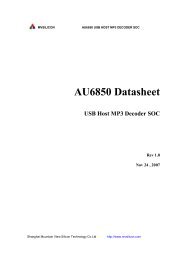
<strong>TW8806</strong>/7 <strong>LCD</strong> FLAT PANEL <strong>TV</strong> / <strong>PC</strong> MONITOR CONTROLLERPRELIMINARYYIN0YIN1OSDYIN2YIN3YOUTCIN0CIN1CIN2VIN0VIN1SOYINVSYNCHSYNCMUXMUXMUX3X Analog Front EndSyncProcessordataSyncProcessorPLLChromaDemodulation4H AdaptiveComb Filterpixel clockhsyncYUV ProcessingMUXSpreadSpectrumPLLColor MatrixLine BuffersScaler /DeinterlacerInput FormatMeasurementAlpha BlendingImage EnhancementGamma / Dither<strong>Panel</strong> Timing GeneratorTCONDACMUXTCON signalsFPR[7:0]FPG[7:0]FPB[7:0]FPVSFPHSFPDEF<strong>PC</strong>LKFPPWCFPBIASROUTGOUTBOUTMC SDAD<strong>TV</strong>CLKD<strong>TV</strong>VSD<strong>TV</strong>HSD<strong>TV</strong>DED<strong>TV</strong> I/FRegisters2 WireSerial BusMC SCLMC SIAD<strong>TV</strong>D[23:0]Figure 1 <strong>TW8806</strong>/7 <strong>Flat</strong> <strong>Panel</strong> <strong>TV</strong>/<strong>Monitor</strong> controller functional block diagramTECHWELL, INC. 6 REV B03/15/2006
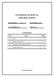
<strong>TW8806</strong>/7 <strong>LCD</strong> FLAT PANEL <strong>TV</strong> / <strong>PC</strong> MONITOR CONTROLLERPRELIMINARYAnalogRGB/YPbPrNTSC / PAL / SECAMTunerDigitalRGB/YPbPrTechwell<strong>TW8806</strong>/7AudioAmpMicro-<strong>Controller</strong>Digital <strong>LCD</strong> <strong>Panel</strong>Figure 2 <strong>TW8806</strong>/7 <strong>Flat</strong> <strong>Panel</strong> <strong>TV</strong>/<strong>Monitor</strong> controller system block diagramFunctional DescriptionOverviewTechwell’s <strong>TW8806</strong>/7 <strong>Flat</strong> <strong>Panel</strong> <strong>TV</strong>/<strong>Monitor</strong> controller is a low cost high quality TFT panel controller withembedded NTSC/PAL/SECAM <strong>TV</strong> decoder. This unique level of mixed signal integration enables thepanel to be used as a stand-alone analog <strong>TV</strong>. An integrated YPbPr component input allows directconnection to DVD sources. Separated digital inputs allow it to be used as a high quality computer monitor.It incorporates easy-to-operate and powerful features in a single package for multi-purpose <strong>PC</strong> displayand <strong>LCD</strong>/<strong>TV</strong> entertainment systems.The <strong>TW8806</strong>/7 contains all the logic required to convert standard <strong>TV</strong>, D<strong>TV</strong>, and <strong>PC</strong> monitor signals to thedigital control and data signals required to drive various TFT panel types. It supports TFT panel resolutionsup to WXGA.The chip accepts CVBS (composite) analog input or S-video analog input or YPbPr input for use as avideo monitor. Up to four physical CVBS inputs or three S-video input or two component input or two RGBinput can be connected synchronously.The integrated analog front-end contains 3 ADCs with clamping circuits and Automatic Gain Control(AGC) circuit to minimize external component count. It employs a 4H, 5-line adaptive comb filter andproprietary Y/C processing technologies to produce exceptionally high quality pictures.The chip's internal logic synchronizes the panel frame rate to the incoming input frame rate. A high qualityimage-scaling engine is used to convert the lower resolution formats or high resolution D<strong>TV</strong> formats to theoutput panel resolution. An internal de-interlacing engine also allows interlaced video to be supported.TECHWELL, INC. 7 REV B03/15/2006
<strong>TW8806</strong>/7 <strong>LCD</strong> FLAT PANEL <strong>TV</strong> / <strong>PC</strong> MONITOR CONTROLLERPRELIMINARYAnalog Front-endSync ProcessingOn Screen Display is supported through on-chip OSD ROM/RAM combination for maximum flexibility. AClosed Caption decoder is built in. The <strong>TW8806</strong>/7 also accepts a 24 bit digital RGB input from externaldigital sources for use as Navigation monitor. In addition, it accepts 8/16/24 bits digital YCbCr input fordirect connection with other digital source like MPEG decoder.The <strong>TW8806</strong>/7 also supports TFT panel power sequencing, DPMS (VESATM Display PowerManagement Signaling) signaling and power management. The control interface is a 2-wire serial businterface. The <strong>TW8806</strong>/7 core operates at 1.8 V, the IO at 3.3 V and packaged in a 128-pin PQFPpackage.The analog front-end converts analog video signals to the required digital format. There are three analogchannels with ADCs and clamping circuits. The Y channel has 4-input multiplexer, and a variable gainamplifier for automatic gain control (AGC). Its four inputs are identified as YIN0, YIN1, YIN2, and YIN3.There are three C channels. Its three inputs are identified as CIN0, CIN1 and CIN2. There are two Vchannels, VIN1 and VIN0. The clamping level of different channel depends on the selection of input formatenabled.Video Source SelectionThere are total 9 analog inputs for maximum flexibility. Software selectable analog inputs allow severalpossible input combinations:1. Up to four composite video inputs.2. Up to three S-video inputs.3. Up to two sets of YPbPr or RGB component inputsClamping and Automatic Gain ControlAll three analog channels have built-in clamping circuit that restore the signal DC level. The clamp level foreach channel is programmable depending on the input format. The actual clamping operation isautomatic through internal feedback loop.When operating in the composite input mode, the Automatic Gain Control (AGC) of the Y channel adjustsinput gain so that the sync tip is at a desired level. The white peak protection logic is included to preventsaturation in the case of abnormal proportion between sync and white peak level. The independentprogrammable gain control for each channel is also available in the RGB mode.Analog to Digital Converter<strong>TW8806</strong>/7 contains three 9-bit ADCs that consume less power than conventional flash ADC. The ADCcan be driven by different clock source depending on the mode of decoding.The sync processor of <strong>TW8806</strong>/7 video decoder detects horizontal synchronization and verticalsynchronization signals in the composite video or in the Y signal of an S-Video or component signal. Theprocessor contains a digital phase-locked-loop and decision logic to achieve reliable sync detection instable signal as well as in unstable signals such as those from VCR playback. In the case of componentvideo mode, it provides synchronization as well as format detection for various HD formats. In the RGBmode, it also provides the separation of the SOG input.TECHWELL, INC. 8 REV B03/15/2006
<strong>TW8806</strong>/7 <strong>LCD</strong> FLAT PANEL <strong>TV</strong> / <strong>PC</strong> MONITOR CONTROLLERPRELIMINARYColor DecodingY/C separationThe color-decoding block contains the luma / chroma separation for the composite video signal and multistandardcolor demodulation. For NTSC and PAL standard signals, the luma / chroma separation can bedone either by comb filter or notch/band-pass filter combination. For SECAM standard signals, onlynotch/band-pass filter is available. The default selection for NTSC/PAL is comb filter.In the case of comb filter, the <strong>TW8806</strong>/7 separates luma (Y) and chroma (C) of a NTSC/PAL compositevideo signal using a proprietary 4H adaptive comb filter. The filter uses four line buffers. Adaptive logiccombines the upper-comb and the lower-comb results based on the signal changes among the previous,current and next lines. This technique leads to good Y/C separation with small cross luma and cross colorat both horizontal and vertical edges,Due to the line buffer used in the comb filter, there is always two lines processing delay in the outputimages no matter what standard or filter option is chosen.If notch/band-pass filter is selected, the characteristics of the filters are shown in the filter curve section.Color demodulationThe color demodulation for NTSC and PAL standard is done by first quadrature mixing the chroma signalto the base band. The mixing frequency is equal to the sub-carrier frequency for NTSC and PAL. After themixing, a low-pass filter is used to remove carrier signal and yield chroma components. The low-pass filtercharacteristic can be selected for optimized transient color performance. For the PAL system, the PAL IDor the burst phase switching is identified to aid the PAL color demodulation.For SECAM, the mixing frequency is 4.286Mhz. After the mixer and low-pass filter, it yields the FMmodulated chroma. The SECAM demodulation process therefore consists of low-pass filter, FMdemodulator and de-emphasis filter. The filter characteristics are shown in filter curve section. During theFM demodulation, the chroma carrier frequency is identified and used to control the SECAM colordemodulation.The sub-carrier signal for use in the color demodulator is generated by direct digital synthesis PLL thatlocks onto the input sub-carrier reference (color burst). This arrangement allows any sub-standard ofNTSC and PAL to be demodulated easily.During S-video operation, the Y signal bypasses the comb filter. The C signal connects directly to the colordemodulator. During component input operation, all the blocks are bypassed.Automatic Chroma Gain ControlThe Automatic Chroma Gain Control (ACC) compensates for reduced amplitudes caused by highfrequencyloss in video signal. In the NTSC/PAL standard, the color reference signal is the burst on theback porch. This color-burst amplitude is calculated and compared to standard amplitude. The chroma(Cx) signals are then increased or decreased in amplitude accordingly. The range of ACC control is –6dbto +24db.Low Color Detection and RemovalFor low color amplitude signals, black and white video, or very noisy signals, the color will be “killed”. Thecolor killer uses the burst amplitude measurement to switch-off the color when the measured burstamplitude falls below a programmed threshold. The threshold has programmed hysteresis to preventoscillation of the color killer operation. This function can be disabled by programming a low threshold value.TECHWELL, INC. 9 REV B03/15/2006
<strong>TW8806</strong>/7 <strong>LCD</strong> FLAT PANEL <strong>TV</strong> / <strong>PC</strong> MONITOR CONTROLLERPRELIMINARYAutomatic standard detectionThe <strong>TW8806</strong>/7 has build-in automatic standard discrimination circuitry. The circuit uses burst-phase,burst-frequency and frame rate to identify NTSC, PAL or SECAM color signals. The standards that can beidentified are NTSC (M), NTSC (4.43), PAL (B, D, G, H, I), PAL (M), PAL (N), PAL (60) and SECAM (M).Each standard can be included or excluded in the standard recognition process by software control. Theidentified standard is indicated by the Standard Selection (SDT) register. Automatic standard detectioncan be overridden by software controlled standard selection.Video Format support<strong>TW8806</strong>/7 supports all common video formats as shown in Table 1. The video decoder needs to beprogrammed appropriately for each of the composite video input formats.Table 1. Video Input Formats Supported by the <strong>TW8806</strong>/7Format Lines Fields Fsc CountryNTSC-M 525 60 3.58 MHz U.S., many othersNTSC-Japan (1) 525 60 3.58 MHz JapanPAL-B, G 625 50 4.43 MHz ManyPAL-D 625 50 4.43 MHz ChinaPAL-H 625 50 4.43 MHz BelgiumPAL-I 625 50 4.43 MHz Great Britain, othersPAL-M 525 60 3.58 MHz BrazilPAL-CN 625 50 3.58 MHz ArgentinaSECAM 625 50 4.406MHz4.250MHzPAL-60 525 60 4.43 MHz ChinaFrance, Eastern Europe,Middle East, RussiaNTSC (4.43) 525 60 4.43 MHz TranscodingNotes: (1). NTSC-Japan has 0 IRE setup.Component ProcessingLuminance ProcessingThe <strong>TW8806</strong>/7 adjusts brightness by adding a programmable value (in register BRIGHTNESS) to the Ysignal. It adjusts the picture contrast by changing the gain (in register CONTRAST) of the Y signal.The <strong>TW8806</strong>/7 video decoder also performs a coring function. It can force all values below a certain level,programmed in the Coring Control Register, to zero. This is useful because human eyes are sensitive tovariations in nearly black images. Changing levels near black to true black, can make the image appearsclearer.TECHWELL, INC. 10 REV B03/15/2006
<strong>TW8806</strong>/7 <strong>LCD</strong> FLAT PANEL <strong>TV</strong> / <strong>PC</strong> MONITOR CONTROLLERPRELIMINARYSharpnessThe <strong>TW8806</strong>/7 also provides a sharpness control function through control registers. It provides the controlin 16 steps up to +12db. The center frequency of the enhancement curve is selectable by software control.It also provides a high frequency coring function to minimize the amplification of high frequency noise. Thecoring level is adjustable through the Coring Control register. To further enhance the image, aprogrammable vertical peaking function is provided for up to +6db of enhancement. A programmablecoring level can be adjusted to minimize the noise enhancement.CTIThe <strong>TW8806</strong>/7 provides the Color Transient Improvement function to further enhance the image quality.The CTI enhance the color edge transient without any hue distortion.Hue and SaturationWhen decoding NTSC signals, <strong>TW8806</strong>/7 can adjust the hue of the chroma signal. The hue is defined asa phase shift of the subcarrier with respect to the burst. This phase shift can be programmed through acontrol register.The color saturation can be adjusted by changing the gain of Cb and Cr signals for all NTSC, PAL andSECAM formats. The Cb and Cr gain can be adjusted independently for flexibility.Digital Input SupportTFT <strong>Panel</strong> SupportIn addition to analog inputs, the <strong>TW8806</strong>/7 has a 24-bit digital input for YCbCr or RGB data. ExternalADCs can be used to make the conversion from analog component inputs to digital YCbCr or RGB tosupport of D<strong>TV</strong> 480p, 720p, and 1080i, or <strong>PC</strong> VGA inputs from QVGA to WXGA. The input includesVSYNC, HSYNC, pixel clock and the optional data qualifier. For interlaced video, the timing relationshipbetween VSYNC and HSYNC determine the field flag. The optional data qualifier is needed when inputvideo data is not continuously valid within a line.The <strong>TW8806</strong> supports varieties of Digital active matrix TFT panels with one pixel per clock mode. Itsupports panel with resolution up to WXGA resolution.The TW8807 supports varieties of Analog active matrix TFT panels with one pixel per clock mode. Itsupports panel with source driver frequency up to 40MHz.DitheringIf the color depth of the input data is larger than the <strong>LCD</strong> panel color depth, the <strong>TW8806</strong>/7 can be set todither the image. Up to four bits of apparent color depth can be added with the internal dithering ability ofthe <strong>TW8806</strong>/7. This allows <strong>LCD</strong> panels with 4, 6 or 8 bits per color per pixel to display up to 16.8 millioncolors and <strong>LCD</strong> panels with 3 bits per color per pixel to can display up to 2.1 million colors.The <strong>TW8806</strong>/7 uses both spatial and frame modulation dithering. When dithering with the least significant4-bits of input data the <strong>TW8806</strong>/7 uses spatial modulation with 4x4 blocks of pixels. When dithering withthe least significant 1 to 3 bits of input data, the <strong>TW8806</strong>/7 uses both spatial modulation with 2x2 pixelblocks, and frame modulation.TECHWELL, INC. 11 REV B03/15/2006
<strong>TW8806</strong>/7 <strong>LCD</strong> FLAT PANEL <strong>TV</strong> / <strong>PC</strong> MONITOR CONTROLLERPRELIMINARYImage ControlInput Image ControlThe input cropping control provides a way for programming the active display window region for theselected input video or graphic. In the normal operation, the first active line starts with the VSYNC signal.This and vertical active length register setting are used to determine the active vertical window. The activepixel starts HSYNC. This and the horizontal active width register are used to determine the activehorizontal window. The vertical window is programmed in line increments. The horizontal window isprogrammed in one pixel increments for single pixel input mode or two pixels increments for double pixelsinput mode. If data qualifier is used, then only qualified pixels will be counted in the window size.Image ScalingThe <strong>TW8806</strong>/7 internal image-scaling engine operates in several modes. The first is the bypass mode. Noimage scaling is done in this mode. The number of active output lines per frame and the number of activeoutput pixels per line are identical to the input active lines and pixels, respectively. This mode is best usedfor displaying computer graphic at panel's native resolution.By default, the input active window is zoomed up to the full screen for display. This is used for noninterlaceddata like <strong>PC</strong> graphics or progressive scan video. The vertical and horizontal magnification ratiocan be adjusted independently. Since the <strong>TW8806</strong>/7 has no frame buffer, the zoom ratio and output clockrate should be coordinated appropriately to avoid internal buffer over-run.The <strong>TW8806</strong>/7 has a de-interlacing mode to process interlaced video inputs. In this mode, every inputfield is zoomed to the full output frame resolution. A proprietary low angle compensation circuitryadaptively corrects the interpolation process to result in smooth video rendering. The de-interlaced fieldscan also be properly compensated to have fields aligned correctly to avoid any artifacts. The offset can beprogrammed to provide maximum flexibility.The horizontal scaler can be programmed to perform panoramic or water-glass scaling for displaying 4:3input on a 16:9 display.Image Enhancement ProcessingAdaptive Black/White StretchThis feature is to expand dynamic range of the input image, which creates more vivid image impression.Favorite Color enhancementThis feature allows enhancement of color that is not primary color. Up to three user programmable colorscan be selected for enhancement. The gain for each color selected is adjustable for maximum flexibility. Ityields rich and colorful video images.TECHWELL, INC. 12 REV B03/15/2006
<strong>TW8806</strong>/7 <strong>LCD</strong> FLAT PANEL <strong>TV</strong> / <strong>PC</strong> MONITOR CONTROLLERPRELIMINARYDisplay TimingThe <strong>TW8806</strong>/7 is operated in Frame Sync mode only with no external memory required. In this mode, theoutput frame rate is synchronized with the input frame rate. Since there is no frame buffer, the displayclock frequency and zoom ratio have to be properly selected to match the panel resolution. The internalscaling engine absorbs the difference between the input line rate and output line rate as well as thedifference between the input pixel rate and output pixel rate.F<strong>PC</strong>LKFPHSFPDEFPR/G/BFPVSFPHSFPDEFigure 3 <strong>Flat</strong> <strong>Panel</strong> Output SignalsThe frequency of the <strong>Flat</strong> <strong>Panel</strong> Clock Output pin can be controlled by an internal frequency multiplierbased on the video decoder clock source, or by an external oscillator connected to the PLLCKI pin. Whenthe internal frequency multiplier is being used, the frequency of the <strong>Flat</strong> <strong>Panel</strong> Clock Output signal isdetermined by the following formula.Frequency F<strong>PC</strong>LK = 27MHz x 32 x FREQ2 21 x 2 POSTColor Space ConversionThe <strong>TW8806</strong>/7 has built-in YCbCr to RGB color space converter for the internal decoder output and thedigital YCbCr input. The internal circuit will clamp the Y data value to the range of 16 to 235 for an 8-bitinput. It also clamps the CbCr data value to the range of 16 to 240 in compliance with the CCIR601standard.TECHWELL, INC. 13 REV B03/15/2006
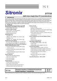
<strong>TW8806</strong>/7 <strong>LCD</strong> FLAT PANEL <strong>TV</strong> / <strong>PC</strong> MONITOR CONTROLLERPRELIMINARYOn Screen DisplayThe <strong>TW8806</strong>/7 supports built-in OSD controller with integrated character ROM and programmable RAMfont. The OSD display is independent of the input active window setting or the scaling ratio.The on-chip OSD controller is a character-based controller. The pre-defined character or graphic bit mapis stored in the internal ROM. There are a total of 202 built-in fonts. Each character is 12 pixels wide by 18pixels high. The characters can be displayed on the screen in four user defined window locations of anysize from 1 to 256 characters. The spaces between characters are also programmable. There is a limit of256 characters that may be displayed on screen at one time in all windows combined. The attributes ofeach window can also be set to give it a shadow effect or 3-D effect. In addition, the characters can beexpanded by a factor of 2,3 or 4 in vertical or horizontal directions and have the italic effect, under lineeffect on a character by character basis.TECHWELL, INC. 14 REV B03/15/2006
<strong>TW8806</strong>/7 <strong>LCD</strong> FLAT PANEL <strong>TV</strong> / <strong>PC</strong> MONITOR CONTROLLERPRELIMINARYFigure 4 Font ROM Characters and AddressesTECHWELL, INC. 15 REV B03/15/2006
<strong>TW8806</strong>/7 <strong>LCD</strong> FLAT PANEL <strong>TV</strong> / <strong>PC</strong> MONITOR CONTROLLERPRELIMINARY<strong>TW8806</strong>/7 Basic register setting flow for Built-in OSD controllerStep_1: OSD_WINDOW_CONFIGURATION setting1. OSD Window Select - bit1:0 = 0~3 of 0x09E2. OSD Window Disable - bit 0 = 0 of 0x09F3. OSD Window Zoom multiplier4. OSD Window Background B Color5. OSD Window Background G Color6. OSD Window Background R Color7. OSD Window Background Color Extension8. OSD Window 3-D Effect Top/Bottom Mode Select9. OSD Window 3-D Effect Level Select10. OSD Window 3-D Effect Enable/Disable11. OSD Window H-Start Location (see details in next page)12. OSD Window V-Start Location (see details in next page)13. OSD Window Width14. OSD Window Height15. OSD Window Border_Line Width16. OSD Window Border_Line B color17. OSD Window Border_Line G color18. OSD Window Border_Line R color19. OSD Window Border_Line Enable20. OSD Window Border Color Extension21. OSD Window Shadow Width22. OSD Window Shadow B color23. OSD Window Shadow G color24. OSD Window Shadow R color25. OSD Window Shadow Enable26. OSD Window Shadow Color Extension27. OSD Window H-Space Width (Between Border_line and Characters)28. OSD Window V-Space Width (Between Border_line and Characters)29. Character H-Space Width (Between Character and Character)30. Character V-Space Width (Between Character and Character)31. OSD Window Alpha Blending Color Select32. OSD Window Alpha Blending Value Control33. Window content start address34. Repeat 1 – 32Step_2: OSD_COLOR_ATTRIBUTE / FONT setting (OSD RAM)1. Enable OSD RAM Access - 0x094 (bit0 = 0)2. OSD RAM Address - 0x095, 0x096- The first address is Step_1_33 Window content start address.3. OSD RAM Data Port High ( Font Address )- 0x097 Data is written to above address automatically.- 0x094_[7] = 0 or 0x097=8’hff : FONT_ROM h00 to hC9 (202 characters)- 0x094_[7] = 1 or 0x097=8’hfe : FONT_RAM h00 to hE2 (Max 227 characters)4. OSD RAM Data Port Bit17( Italic Effect ), Bit18( Under Line Effect ), Bit19( Character Bordering/Shadowing Enable)- 0x094 Bit6, Bit5, Bit4 Data is written to above address automatically.5. OSD RAM Data Port Low ( Color Attribute )TECHWELL, INC. 17 REV B03/15/2006
<strong>TW8806</strong>/7 <strong>LCD</strong> FLAT PANEL <strong>TV</strong> / <strong>PC</strong> MONITOR CONTROLLERPRELIMINARY- 0x098 Data is written to above address automatically.6.Repeat 2), 3), 4), 5)- The address should be increased by one each.Step_3: COLOR LOOK-UP TABLE setting1. Select Color Look-Up Table Write Address - 0x09C (bit[3:0])- BIT[3:0] : These 4 bits specify one of the 16 entries in the look-up table. Each entry is indexed to a differentcolor by its content.- There are 256 colors available; but only sixteen of them are accessible by OSD controller at a given time.BIT[3:0] Default Value0000 00h (000,000,00)0001 03h (000,000,11)0010 1Ch (000,111,00)0011 1Fh (000,111,11)0100 E0h (111,000,00)0101 E3h (111,000,11)0110 FCh (111,111,00)0111 FFh (111,111,11)1000 49h (010,010,01)1001 02h (000,000,10)1010 10h (000,100,00)1011 12h (000,100,10)1100 80h (100,000,00)1101 82h (100,000,10)1110 90h (100,100,00)1111 92h (100,100,10)2. Color Look-Up Table control bits setting - 0x09D- The data of the Look-Up Table is accessed through 0x09D.- An index 0x09D register write strobes the data into the corresponding entry pointed by 0x09C[3:0].- Control BIT[7:5] These bits assigned for R color(select one of 8 R color intensities).- Control BIT[4:2] These bits assigned for G color(select one of 8 G color intensities).- Control BIT[1:0] These bits assigned for B color(select one of 4 B color intensities).R Color Table BIT[7:5]Table SettingValueG Color Table BIT[4:2]Table SettingValueB Color Table BIT[1:0]Table SettingValue000 8’d0 000 8’d0 00 8’d0001 8’d32 001 8’d32 01 8’d64010 8’d64 010 8’d64 10 8’d128011 8’d96 011 8’d96 11 8’d255100 8’d128 100 8’d128101 8’d160 101 8’d160110 8’d192 110 8’d192111 8’d255 111 8’d2553. Repeat 1),2) to program each entry of the Look-Up Table.TECHWELL, INC. 18 REV B03/15/2006
<strong>TW8806</strong>/7 <strong>LCD</strong> FLAT PANEL <strong>TV</strong> / <strong>PC</strong> MONITOR CONTROLLERPRELIMINARYStep_4: FONT_RAM_DATA setting (FONT RAM)1. Enable FONT RAM Access - 0x094 (bit0 = 1)2. Programmable SRAM Address Start Position Setting for Multi-Color Font.- 0x09B3. FONT RAM Address Setting - 8 bits(h00 – hE2) - 0x099- h00~hE2 : Single Font RAM(227 Programmable Characters)- h00~hE2 : Multi-Color Font RAM(75 Programmable Characters)ex) 0x09B == h32 Setting Case h00 ~ h31 : Single Font RAM(50 Programmable Characters) h32 ~ hE2 : Multi-Color Font RAM(59 Programmable Characters)h32(R-color), h33(G-color), h34(B-color) are one set for 1 multi-color font.4. FONT RAM Data Port- 0x09A Data is written to above address automatically.5. Repeat (4) at 27 times for one FONT RAM Data- the internal address automatically increases by one each.6. New FONT RAM Address Setting – 8 bits7. Repeat 3),4),5)- The FONT RAM Address should be increased by one each.Note) As for the FONT RAM configuration and font bit mapping, see the detailed descriptionStep_5: End of OSD setting and Enable OSD1. Disable OSD RAM / FONT RAM Access - 0x094 (bit0 = 0)2. OSD Window Enable - 0x09E bit[1:0] window select 000: Window1, 001: Window2, 010: Window3, 011: Window4- bit0 = 1 of 0x09FTECHWELL, INC. 19 REV B03/15/2006
<strong>TW8806</strong>/7 <strong>LCD</strong> FLAT PANEL <strong>TV</strong> / <strong>PC</strong> MONITOR CONTROLLERPRELIMINARYOSD Window Start Location : Built-in OSD controllerOSD window H_start location (N): 0x09E bit[1:0] window select, 0x0A2,0A0 increment by 1 at a timeN = 0, 1, 2, 3… Pixel 1 when N = 0,1N OSD_Window Start_Pixel1 pixel 1 (begin with pixel 1)2 pixel 23 pixel 3N pixel NOSD window V_start location (M) : 0x09E bit[1:0] window select, 0x0A2,0A1 increment by 1 at a timeM = 0, 1, 2, 3.... Line 1 when M = 0,1M OSD_Window Start_Line1 line 1 (begin with line 1)2 line 23 line 3M line MOSD_RAM ConfigurationAddress012The characters can be displayed on the screen in four userdefined window locations of any size from 1 to 256characters. There is a limit of 256 characters that may bedisplayed on screen at one time in all windows combined.ExampleWindow #1: Address 0 – 2 (3 characters)Window #2: Address 3 – 100 (98 characters)Window #3: Address 101– 254 (154 characters)Window #4: Address 255 (1 character)253254255190TECHWELL, INC. 20 REV B03/15/2006
<strong>TW8806</strong>/7 <strong>LCD</strong> FLAT PANEL <strong>TV</strong> / <strong>PC</strong> MONITOR CONTROLLERPRELIMINARY19 8 70FONT_ADDRESS (12-bits)Bit 19: Character Border/ShadowEffect ONBit 18: Under Line Effect ONBit 17: Italic Effect ONBit 16: FONT_RAM ONBit 15 - 8: FONT AddressATTRIBUTE (8-bits)Bit 7: Character’s Color ExtensionBit 6: Character's background RBit 5: Character's background GBit 4: Character's background BBit 3: Blink ONBit 2: Character RBit 1: Character GBit 0: Character BFONT BIT MAP 12 x 18 dots = 1 characterFONT RAM ADDRESS 7-bitsLine 0123456789101112131415161712 pixels4 pixels0 1 23 4 56 7 89 10 1112 13 1415 16 1718 19 2021 22 2324 25 26FONT RAMADDRESS 8-bitsFONT RAM Addressshould be increasedby each font data.(0 ~ 226)Internal CharacterAddress 5-bitsAutomatically Increases7 6 5 4 3 2 1 0 4 3 2 1 0FONT RAM (6144 x 8 bits)7 6 5 4 3 2 1 0Internal Character Addressautomatically increases byfont data write sequence.(0 ~ 26)ADDRESS01Single color FontORMulti-Color Font3 address areone multi-color fontBit 3 Bit 2 Bit 1 Bit 0Bit 7 Bit 6 Bit 5 Bit 4223225226TECHWELL, INC. 21 REV B03/15/2006
<strong>TW8806</strong>/7 <strong>LCD</strong> FLAT PANEL <strong>TV</strong> / <strong>PC</strong> MONITOR CONTROLLERPRELIMINARY<strong>TW8806</strong>/7 Alpha Blending for OSD WindowThe <strong>TW8806</strong>/7 uses "Alpha Blending" in OSD 4 separation windows & 16 separation colors. Alpha blending mixes(adds) the video signal and OSD signal at the following specified levels. In other words, alpha blending determines thetransparency of the OSD window each color to in relation to video signal. When alpha blending is disabled, only OSDdata is displayed in OSD window.The alpha blending level selection are 4-bit assigned, it can support 8 different level control.The alpha blending level bits and alpha blending color selection bits are in register 0x09E, 0x0AC for each windows(Window Controlby register 0X9E bit[1:0]).alpha[3:0] Video Level0000 0.00 %0001 12.50010 25.00011 37.50100 50.00101 62.50110 75.00111 87.51000 100Alpha Blending Concept :1 – Video LevelOSD dataVideo dataxx+Video LevelTECHWELL, INC. 22 REV B03/15/2006
<strong>TW8806</strong>/7 <strong>LCD</strong> FLAT PANEL <strong>TV</strong> / <strong>PC</strong> MONITOR CONTROLLERPRELIMINARYMicrocontroller InterfaceThe <strong>TW8806</strong>/7 registers are accessed via 2-wire serial bus interface. It operates as a slave device. Serialclock and data lines transfer data from the bus master at a rate up to 400 Kb/s.Power ManagementThe <strong>TW8806</strong>/7 supports panel power sequencing. Typical TFT panels require different parts of the panelpower to be applied in the right sequence to avoid premature damage to the panel. Pins are provided tocontrol the panel backlight generator, digital circuitry and panel driver, separately. The <strong>TW8806</strong>/7 controlsthe power up and power down sequence for the <strong>LCD</strong> panels. The time lapses between different stages ofthe sequence are independently programmable to meet various power sequencing requirements.The <strong>TW8806</strong>/7 also supports VESA TM DPMS for monitor power management. It can detect the DPMSstatus from input sync signals and automatically change into On/Off mode. To support the powermanagement, the <strong>TW8806</strong>/7 has three operating modes: Power On mode, Power Off mode, and <strong>Panel</strong>Off mode. All the DPMS power saving mode will be covered by the Power Off mode.TECHWELL, INC. 23 REV B03/15/2006
<strong>TW8806</strong>/7 <strong>LCD</strong> FLAT PANEL <strong>TV</strong> / <strong>PC</strong> MONITOR CONTROLLERPRELIMINARYClock run-inFrameCodeFigure 5 Typical CC/EDS scan line waveformClosed Captioning and Extended Data ServicesClosed Caption (CC) vertical blanking interval scan lines are on the odd field NTSC line 21. ExtendedData Services (EDS) scan lines are on the even field NTSC line. A Closed Caption (CC) scan line on anNTSC-based system is made of 25 bit periods at a 0.503MHz rate. The data is an analog signal beginningwith a packet header. It contains a Clock Synchronization Code consisting of 14 bits of double-frequencyrun-in clock at 1.006 MHz, a 2-bit framing code. The data of 16 bits/2 bytes follows the packet header.Each of these 2 bytes is a 7 bit + odd parity ASCII character which represents text or control characters forpositioning or display control. For the purposes of CC or EDS, only the Y component of the video signal isused. Therefore, the input composite video has to go through the Y/C separation to extract Y componentfor further decoding. The <strong>TW8806</strong>/7 can be programmed to decode CC or EDS data by setting register0x1B. Since the CC and EDS are independent, there could be one or both in a particular frame. A typicalwaveform is shown in Figure 5.In the CC/EDS decode mode, the decoder monitors the appropriate scan lines looking for the clock run-inand start bits pattern. It found, it locks to the clock run-in, the caption data is sampled and loaded into shiftregisters, and the data is then transferred to the caption data FIFO. The <strong>TW8806</strong>/7 provides a 16 x 10location FIFO for storing CC/EDS data. Once the video decoder detects the start signal in the CC/EDSsignal, it captures the low byte of CC/EDS data first and checks to see if the FIFO is full. If the FIFO is notfull, then the data is stored in the FIFO, and is available to the user through the CC_DATA register (0x1A).The high byte of CC/EDS data is captured next and placed in the FIFO. Upon being placed in the 10-bitFIFO, two additional bits are attached to the CC/EDS data byte by <strong>TW8806</strong>/7’s CC/EDS decoder. Thesetwo bits indicate whether the given byte stored in the FIFO corresponds to CC or EDS data and whether itis the high or low byte of CC/EDS. These two bits are available to the user through the CC_STATUSregister bits CC_EDS and LO_HI, respectively. As stored in the FIFO, LO_HI is bit 8 and CC_EDS is bit 9.Additionally, the <strong>TW8806</strong>/7 stores the results of the parity check in the PARITY_ERR bit in theCC_STATUS register.The 16-location FIFO can hold eight lines worth of CC/EDS data, at two bytes per line. Initially when theFIFO is empty, bit Empty in the CC_STATUS register (0x1A) is set low and indicates that no data isavailable in the FIFO. Subsequently, when data has been stored in the FIFO, the Empty bit is set to logicalhigh. Once the FIFO is half full, the CC_VALID interrupt pin signals to the system that the FIFO contentsshould be read in the near future. The CCVALID bit is enabled via a bit in the CC_STATUS register (0x1A).The system controller can then poll the CCVALID bit in the STATUS register (0x00) to ensure that it wasthe <strong>TW8806</strong>/7 that initiated the CCVALID interrupt.TECHWELL, INC. 24 REV B03/15/2006
<strong>TW8806</strong>/7 <strong>LCD</strong> FLAT PANEL <strong>TV</strong> / <strong>PC</strong> MONITOR CONTROLLERPRELIMINARYWhen the first byte of CC/EDS data is decoded and stored in the FIFO, the data is immediately placed inthe CC_DATA and CC_STATUS registers and is available to be read. Once the data is read from theCC_DATA register, the information in the next location of the FIFO is placed in the CC_DATA andCC_STATUS registers. If the controller in the system ignores <strong>TW8806</strong>/7’s CCVALID bit for a sufficientlylong period of time, then the CC/EDS FIFO will become full and the <strong>TW8806</strong>/7 will not be able to writeadditional data to the FIFO. Any incoming bytes of data will be lost and an overflow condition will occur; bitOverflow in the CC_STATUS register will be set to a logical one. The system may clear the overflowcondition by reading the CC/EDS data and creating space in the FIFO for new information. As a result, theoverflow bit is reset to a logical zero.There will routinely be asynchronous reads and writes to the CC/EDS FIFO. The writes will be from theCC/EDS circuitry and the reads will occur as the system controller reads the CC/EDS data from<strong>TW8806</strong>/7. These reads and writes will sometimes occur simultaneously, and the <strong>TW8806</strong>/7 is designedto give priority to the read operations. In the case where the CC_DATA register data is specifically beingread to clear an overflow condition, the simultaneous occurrence of a read and a write will not cause theoverflow bit to be reset, even though the read has priority. An additional read must be made to theCC_DATA register in order to clear the overflow condition. As always, the write data will be lost while theFIFO is in overflow condition.Two Wire Serial Bus InterfaceThe two wire serial bus interface is used to allow an external micro-controller to write control data to, andread control or other information from the <strong>TW8806</strong>/7 registers. SCLK is the serial clock and SDAT is thedata line. Both lines are pulled high by resistors connected to VDD. ICs communicate on the bus bypulling SCLK and SDAT low through open drain outputs. In normal operation the master generates allclock pulses, but control of the SDAT line alternates back and forth between the master and the slave. ForStart ConditionStop ConditionSDATFigure 6 Definition of two-wire serial bus interface bus start and stopTECHWELL, INC. 25 REV B03/15/2006
<strong>TW8806</strong>/7 <strong>LCD</strong> FLAT PANEL <strong>TV</strong> / <strong>PC</strong> MONITOR CONTROLLERPRELIMINARYSDATDevice ID (1-7)R/WIndex (1-8) Data (1-8)SCLKStartConditionAckAckStopConditionFigure 7 One complete serial bus interface register write sequenceboth read and write, each byte is transferred MSB first, and the data bit is valid whenever SCLK is high.The <strong>TW8806</strong>/7 is operated as a bus slave device. It can be programmed to respond to one of two 7-bitslave device addresses by tying the SIAD (Serial Interface ADdress) pin ether to VDD or GND (See Table2.). If the SIAD pin is tied to VDD, then the least significant bit of the 7-bit address is a “1”. If the SIAD pinis tied to GND then the least significant bit of the 7-bit address is a “0”. The most significant 6-bits are fixed.The 7-bit address field is concatenated with the read/write control bit to form the first byte transferredduring a new transfer. If the read/write control bit is high the next byte will be read from the slave device. Ifit is low the next byte will be a write to the slave. When a bus master (the host microprocessor) drivesSDAT from high to low, while SCLK is high, this is defined to be a start condition (See Figure 6.). Allslaves on the bus listen to determine when a start condition has been asserted.After a start condition, all slave devices listen for the their device addresses. The host then sends a byteconsisting of the 7-bit slave device ID and the R/W bit. This is shown in Figure 7. (For the <strong>TW8806</strong>/7, thenext byte is normally the index to the <strong>TW8806</strong>/7 registers and is a write to the <strong>TW8806</strong>/7 therefore the firstR/W bit is normally low.)After transmitting the device address and the R/W bit, the master must release the SDAT line whileholding SCLK low, and wait for an acknowledgement from the slave. If the address matches the deviceaddress of a slave, the slave will respond by driving the SDAT line low to acknowledge the condition. Themaster will then continue with the next 8-bit transfer. If no device on the bus responds, the mastertransmits a stop condition and ends the cycle. Notice that a successful transfer always includes nine clockpulses.To write to the internal register of the<strong>TW8806</strong>/7, the master sends another 8-bits of data, the <strong>TW8806</strong>/7loads this to the register pointed by the internal index register. The <strong>TW8806</strong>/7 will acknowledge the 8-bitdata transfer and automatically increment the index in preparation for the next data. The master can domultiple writes to the <strong>TW8806</strong>/7 if they are in ascending sequential order. After each 8-bit transfer the<strong>TW8806</strong>/7 will acknowledge the receipt of the 8-bits with an acknowledge pulse. To end all transfers to the<strong>TW8806</strong>/7 the host will issue a stop condition.TECHWELL, INC. 26 REV B03/15/2006
<strong>TW8806</strong>/7 <strong>LCD</strong> FLAT PANEL <strong>TV</strong> / <strong>PC</strong> MONITOR CONTROLLERPRELIMINARYSDATDevice ID (1-7) R/W Index (1-8)SCLKStartConditionAckDevice ID (1-7)R/WData (1-8)Re-startConditionAckStopNack ConditionFigure 8 One complete serial bus interface register read sequenceTable 2 <strong>TW8806</strong> serial bus interface 7-bit slave address and read write bitSerial Bus Interface 7-bit Slave Address1 0 0 0 1 0 SIADRead/Writebit1= Read0=WriteA <strong>TW8806</strong>/7 read cycle has two phases. The first phase is a write to the internal index register. Thesecond phase is the read from the data register. (See figure 8). The host initiates the first phase bysending the start condition. It then sends the slave device ID together with a 0 in the R/W bit position. Theindex is then sent followed by either a stop condition or a second start condition. The second phase startswith the second start condition. The master then resends the same slave device ID with a 1 in the R/W bitposition to indicate a read. The slave will transfer the contents of the desired register. The master remainsin control of the clock. After transferring eight bits, the slave releases and the master takes control of theSDAT line and acknowledges the receipt of data to the slave. To terminate the last transfer the master willissue a negative acknowledge (SDAT is left high during a clock pulse) and issue a stop condition.TECHWELL, INC. 27 REV B03/15/2006
<strong>TW8806</strong>/7 <strong>LCD</strong> FLAT PANEL <strong>TV</strong> / <strong>PC</strong> MONITOR CONTROLLERPRELIMINARYTest ModesThe <strong>TW8806</strong>/7 contains more than 256 index registers. Since the index data for serial bus access is onlyeight bits wide, a page mechanism is used to access these registers. The bit 0 of index 0xFF is used toselect either the first page of 255 registers or the second page of 255 registers. In the register map, theindex consists of 9 bits. The MSB denotes the content of bit 0 of index 0xFF, and the rest 8 bitscorrespond to the serial bus index data. Hence 0x000 denotes the index 0 of page 0, while 0x100denotes the index 0 of page 1. Index 0xFF is shared between page 0 and page 1.The TEST1 input pin provides test mode selection. If this pin is low at the rising edge of the RESET# pinand remains low, the <strong>TW8806</strong>/7 is in its normal operating mode. Table 4 shows the other test modesmade available with this pin.Table 3 Test modesTest mode TEST1 TEST1 DescriptionBeforeRESET#rising edgeAfterRESET#rising edgeNormal 0 0 Normal operationOutput tri-state 0 1 In this mode, all pin output drivers are tri-stated. Pin leakage currentparameters can be measured.Outputs high 1 0 In this mode, all pin output drivers are forced to the high output state. V OH andI OH can be measured.Outputs low 1 1 In this mode, all pin output drivers are forced to the low output state. V OL andI OL can be measured.TECHWELL, INC. 28 REV B03/15/2006
<strong>TW8806</strong>/7 <strong>LCD</strong> FLAT PANEL <strong>TV</strong> / <strong>PC</strong> MONITOR CONTROLLERPRELIMINARY<strong>TW8806</strong>/7 Register SummaryThe registers are organized in functional groups in this Register Summary. A register containing different functional bitsmay appear more than once in different functional groups. If a particular bit of a register is not related to that functionalgroup, it is printed in smaller font than those related. For example, bit 7 of index 006 is classified as “General” and isprinted in normal size; the other bits in this register are printed in smaller size for their functionality is not classified as“General”.GeneralIndex(HEX)7 6 5 4 3 2 1 0Resetvalue000 ID REV 21hXFF RPTMTHD SELFCNT SELFTHS SACNT ENALU NOFSEL PAGE_1 40hDecoderIndex(HEX)7 6 5 4 3 2 1 0Resetvalue001 VDLOSS HLOCK SLOCK FIELD VLOCK CCVALID MONO DET50 00h002 CSEL1 FC27 IFSEL YSEL CSEL0 VSEL 40h003 - -004 - CKHY - 00h005 - -006 SRESET PDYBF VREF AGC_EN CLKPDN Y_PDN C_PDN V_PDN -007 VDELAY_HI VACTIVE_HI HDELAY_HI HACTIVE_HI 12h008 VDELAY_LO 12h009 VACTIVE_LO 20h00A HDELAY_LO 10h00B HACTIVE_LO D0h00C PBW DEM PALSW SET7 COMB HCOMP YCOMB PDLY CCh00D * * WSSEN CCODDLINE 15h00E CRCERR WSSFLD WSS1 -00F WSS2 -010 BRIGHTNESS 00h011 CONTRAST 5Ch012 SCURVE VSF CTI SHARPNESS 11h013 SAT_U 80h014 SAT_V 80h015 HUE 00h016 - -017 SHCOR - VSHP 30h018 CTCOR CCOR VCOR CIF 44h019 - -CCVALID_01AENEDS_EN CC_EN PARITY FF_OVF FF_EMP CC_EDS LO_HI 00h01B CC_DATA -01C DTSTUS STDNOW ATREG STANDARD 17h01D START PAL60 PALCN PALM NTSC4 SECAM PALB NTSCM 7Fh01E - CVSTD CVFMT 08h01F TEST 00hTECHWELL, INC. 29 REV B03/15/2006
<strong>TW8806</strong>/7 <strong>LCD</strong> FLAT PANEL <strong>TV</strong> / <strong>PC</strong> MONITOR CONTROLLERPRELIMINARYDecoder (Cont.)Index(HEX)7 6 5 4 3 2 1 0Resetvalue020 CLPEND CLPST 50h021 NMGAIN WPGAIN AGCGAIN8 42h022 AGCGAIN F0h023 PEAKWT D8h024 CLMPLD CLMPL BCh025 SYNCTD SYNCT B8h026 MISSCNT HSWIN 44h027 <strong>PC</strong>LAMP 2Ah028 VLCKI VLCKO VMODE DE<strong>TV</strong> AFLD VINT 00h029 BSHT VSHT 00h02A CKILLMAX CKILLMIN 78h02B HTL VTL 44h02C CKLM YDLY HFLT 30h02D HPLC EVCNT PALC SDET TBC_EN BYPASS SYOUT HADV 14h02E HPM ACCT SPM CBW A5h02F NKILL PKILL SKILL CBAL FCS LCS CCS BST E0h030 SID_FAIL PID_FAIL FSC_FAILSLOCK_FAILCSBAD MVCSN CSTRIPE CTYPE -031 VCR WKAIR WKAIR1 VSTD NINTL WSSDET EDSDET CCDET -032 HFREF/GVAL/PHERRDO/CGAINO/BAMPO/MINAVG/SYTHRD/SYAMP -033 FRM YNR CLMD PSP 05h034 INDEX NSEN/SSEN/PSEN/WKTH 1Ah035 CTEST YCLEN CCLEN VCLEN GTEST VLPF CKLY CKLC 00h036-37 -038 DEC_SEL - - - FBPY FB<strong>PC</strong> FBPV MIX 80hTECHWELL, INC. 30 REV B03/15/2006
<strong>TW8806</strong>/7 <strong>LCD</strong> FLAT PANEL <strong>TV</strong> / <strong>PC</strong> MONITOR CONTROLLERPRELIMINARY<strong>LCD</strong>C – Input ControlIndex(HEX)7 6 5 4 3 2 1 0Resetvalue040 OFDM RVODDP SLVSFLD ECSYNC DE_POL HS_POL VS_POL CK_POL 00h041 ECOAST COAST_P EXP_DE DE/HS# * D<strong>TV</strong>CK_DELAY 20h042 VGAFLD SELFVS VSDL_656 SELFTHS CR601 INPUT_DATA_BUS_ROUTING 04h043 PLLOS * <strong>PC</strong>KCAP * * DECPOL 22h044 COAST_RANGE * B8601 IP_COLOR_FMT IP_SEL 08h045 OFD_DET_END OFD_DET_ST 54h046 CSYNC_VS_OFFSET 20h047 IP_HA_ST_LO 00h048 IP_HA_END_LO CFh049 IP_HA_END_HI * IP_HA_ST_HI 20h04A IP_VA_ST_ODD_LO 13h04B IP_VA_ST_EVN_LO 13h04C IP_VA_LENGTH_LO 00h04D * IP_VA_LENGTH_HI IP_VA_ST_EVN_HI IP_VA_ST_ODD_LO 30h04E * GPIOEN2 GPIOEN1 GPIOEN0 IRQ_AL * * * 00h04F GPIO1_P GPIO1_SRC GPIO1_D GPIO0_P GPIO0_SRC GPIO0_D 00h<strong>LCD</strong>C – Input MeasurementIndex(HEX)7 6 5 4 3 2 1 0Resetvalue050 * 00h051 MEA_WIN_H_ST_LO 20h052 MEA_WIN_H_END_LO FFh053 MEA_WIN_H_END_HI * MEA_WIN_H_ST_HI 10h054 MEA_WIN_V_ST_LO 20h055 MEA_WIN_V_END_LO FAh056 * MEA_WIN_V_END_HI * MEA_WIN_V_ST_HI 00h057 RESULT_0 -058 RESULT_1 -059 RESULT_2 -05A RESULT_3 -05B RESULT_SEL FIELD_SEL RD_LOCK MEA_ST 00h05C U_27M NOISE_MASK ERR_TOLER CHG_DET 00h05D THRESHOLD_FOR_ACT_DET ENALU NOFSEL * 30hTECHWELL, INC. 31 REV B03/15/2006
<strong>TW8806</strong>/7 <strong>LCD</strong> FLAT PANEL <strong>TV</strong> / <strong>PC</strong> MONITOR CONTROLLERPRELIMINARY<strong>LCD</strong>C - ScalingIndex(HEX)7 6 5 4 3 2 1 0Resetvalue060 X_SCALE_UP_MID B4h061 X_SCALE_DOWN_LO 80h062 Y_SCALE_UP/DOWN_MID 50h063PANORA_MA* * ZOOMBP Y_SCALE_UP/DOWN_HIY_SCALE_UP/DOWN_MIX_SCALE_DOWN_HIX_SCALE_UP_HI064 X_OFFSET 00h065 Y_OFFSET_EVEN 80h066 H_NON_DISPLAY_PIXEL / H_PANORAMA_PIXEL 00h067 LB_CE * * * * *H_NON_DISPLAY /H_PANORMAN_PIXEL00h068 X_SCALE_UP_LO (AT_THE_SIDE_FOR_PANORAMA) 00h069 X_SCALE_UP_LO 00h06A Y_SCALE_UP/DOWN_LO 00h06B Y_OFFSET_ODD 00h00h<strong>LCD</strong>C – Image AdjustmentIndex(HEX)7 6 5 4 3 2 1 0Resetvalue070 * INDX_CB HUE 20h071 CONTRAST_R / CONTRAST_Y 80h072 CONTRAST_G / CONTRAST_Cb 80h073 CONTRAST_B / CONTRAST_Cr 80h074 BRIGHTNESS_R / BRIGHTNESS_Y 80h075 BRIGHTNESS_G 80h076 BRIGHTNESS_B 80h077 H_SHARP_COR H_SHARPNESS 3FhH_SHARP_F078REQ* DYNR HFLT 0Ah079 * * * * -07A * -07B * * * -07C T_BW * PEDLVL WHTLVL UBTILT UWTILT BPBW * 1Ch07D BW_LINE_ST_LO 08h07E BW_LINE_END_LO F6h07F BW_LINE_END_HI BW_LINE_ST_HI 08h080 BW_H_DELAY 10h081 * BW_H_FILTER_GAIN 0Dh082 * BW_V_FILTER_GAIN 03h083 BW_LDIFF 00h084 BW_BLACK_TILT 67h085 BW_WHITE_TILT 94h086 BW_BLACK_LIMIT 18h087 BW_WHITE_LIMIT E8h088 BW_MODE * CAh089 * BW_GAIN 02h08A * * * BW_STROFF 0Ah08B * * * BW_STRHYS 04hTECHWELL, INC. 32 REV B03/15/2006
<strong>TW8806</strong>/7 <strong>LCD</strong> FLAT PANEL <strong>TV</strong> / <strong>PC</strong> MONITOR CONTROLLERPRELIMINARY<strong>LCD</strong>C – OSDIndex(HEX)7 6 5 4 3 2 1 0Resetvalue090 * * * * * * * * -091 * * * * * * * * -092 * * * * E_VDLY 06h093 * * * * * * * * -094 F_RAM ITALICUNDER_LINECBS_EN FR_ADD[1:0] FRAM_CLFR_RAC_SEL095 W1END VBEND CH_EXT RD978_SEL * * * * 00h096 Serial_Bus_OSD_RAM_ADDR[7:0] 00h097 Serial_Bus_OSD_RAM_DATA_HI (Font Data) -098 Serial_Bus_OSD_RAM_DATA_LO (Font Attribute) -099 Serial_Bus_FONT_RAM_ADDR 00h09A Serial_Bus_FONT_RAM_DATA -09B START_SRAM_ADDRESS 31h09C RAM_D16 * * OSD_OFF CH_COLOR_LOOKUP_ADDR 00h09D CH_COLOR_LOOKUP_DATA 00h09E WIN_ALPHA_COLOR_SEL * * WIN_CON_SEL 00h09F WIN_C WIN_R WIN_G WIN_B WIN_3D WIN_E3D WIN_E3L WIN_EN 00h0A0 * * WIN_V_ST[9:8] * WIN_H_ST[10:8] 00h0A1 WIN_H_ST[7:0] 00h0A2 WIN_V_ST[7:0] 00h0A3 * * WIN_WIDTH 00h0A4 * * WIN_HEIGHT 00hWINBC_E0A5 NWINBC_R WINBC_G WINBC_B WINBC_WIDTH 00h0A6 WINBC WIN_BORDER_H_WIDTH 00h0A7 * WIN_BORDER_V_WIDTH 00h0A8 WIN_CHARACTER_V_SPACE WIN_CHARACTER_H_SPACE 00h0A9 WIN_V_ZOOM WIN_H_ZOOM * * * * 00h0AA WIN_CNT_ST_ADDR[7:0] 00h0AB WINS_E WINS_R WINS_G WINS_B WIN_SHADOW_WIDTH 00h0AC * * * * WIN_ALPHA_BLENDING 00h0ADWINSCWINMC_ENCV_EXTWINC_BSE_SE0AE * * * *WINC_SHAD_CWIN_C_V_SPACE[4]WINC_SHAD_RWIN_C_H_SPACE[4]WINC_SHAD_GWIN_SHA_WIDTH[4]WINC_SHAD_BWINBC_WIDTH[4]00h00h00hTECHWELL, INC. 33 REV B03/15/2006
<strong>TW8806</strong>/7 <strong>LCD</strong> FLAT PANEL <strong>TV</strong> / <strong>PC</strong> MONITOR CONTROLLERPRELIMINARY<strong>LCD</strong>C – Display ControlIndex(HEX)7 6 5 4 3 2 1 0Resetvalue0B0 DBLOP FPDEAH FPHSAH FPVSAH RVF<strong>PC</strong>K RVHILO RVBIT F<strong>PC</strong>LKC 40h0B1 TCONS * DEMODE OP6B TRIFP F<strong>PC</strong>LK_DELAY 00h0B2 FPHS_PERIOD_LO 3Ah0B3 FPHS_ACTIVE_PW 10h0B4 FP_H_BACK_PORCH 1Bh0B5 FPDE_ACTIVE_LO 00h0B6 USEREG FPDE_ACTIVE_HI FPHS_PERIOD_HI 42h0B7 FPVS_PERIOD_LO 26h0B8 FPVS_ACTIVE_PW 06h0B9 FP_V_BACK_PORCH 1Fh0BA FP_V_ACTIVE_LO 00hEARLY_S0BBTFP_V_ACTIVE_HI * FPVS_PERIOD_HI 33h0BC * DITHER_OPTION * DITHER_FORMAT 00h0BD VSYNC_DELAY 08h0BE FRCLONG FRCSHRT EPWMX PWM_AL VH_DISHA FRERUN AUTOC SDELVS 00h0BF DISP_SNGFLD RVF_AC <strong>TV</strong>VSF4 NOEVNI EVNDLY 00h0C0 INI_CNT_EVN_LO 00h0C1 INI_CNT_ODD_LO 00h0C2 INI_CNT_EVN_HI INI_CNT_ODD_HI 00h0C3 EVNPM NUMBER_OF_LINES_TO_BLACK_OUT 00h0C4 PWMC_D2 PWM_COUNTER 40h0C5 TCON_REG_ADDR 00h0C6 TCON_REG_DATA -<strong>LCD</strong>C – Status & InterruptIndex(HEX)7 6 5 4 3 2 1 0Resetvalue0D0 LB_OVF LB_UNF V_LOS_C H_LOS_C VDLOS_C V_LOSS H_LOSS SYNCS -0D1 M_RDY PWS_C V_PRD_C H_PRD_C LBOUNF VDC_C VH_LOS_C SYNCS_C -0D2 IRQ_B_B17 IRQ_B_B16 IRQ_B_B15 IRQ_B_B14 IRQ_B_B13 IRQ_B_B12 IRQ_B_B11 IRQ_B_B10 FFh0D3 * * IRQ_B_VD IRQ_B_CC IRQ_B_50 07h<strong>LCD</strong>C – Power ManagementIndex(HEX)7 6 5 4 3 2 1 0Resetvalue0D4 DIVDE_DOWN_COUNTER_MSB 00h0D5 <strong>PC</strong>LK_PDN EN_PIN5 PWR_STATE MANPWR EDPMS PWR_STATE_WT 00h0D6 SUSPEND_STDBY_CNT ON_SUSPEND_CNT 00h0D7 OFF_STDBY_CNT STDBY_OFF_CNT 00h0D8 STDBY_SUSPEND_CNT SUSPEND_ON_CNT 00hTECHWELL, INC. 34 REV B03/15/2006
<strong>TW8806</strong>/7 <strong>LCD</strong> FLAT PANEL <strong>TV</strong> / <strong>PC</strong> MONITOR CONTROLLERPRELIMINARY<strong>LCD</strong>C – Color EnhancementIndex(HEX)7 6 5 4 3 2 1 0Resetvalue0DA CE_CENTER0 3Dh0DB CE_CENTER1 C3h0DC CE_CENTER2 FCh0DD CE_EN CE_SPREAD0 CE_GAIN0 00h0DE * CE_SPREAD1 CE_GAIN1 00h0DF * CE_SPREAD2 CE_GAIN2 00h<strong>LCD</strong>C – GammaIndex(HEX)7 6 5 4 3 2 1 0Resetvalue0F0 GAMAE_R GAMAE_G GAMAE_B * AUTO_INC GAMMA_RGB_INDX 00h0F1 GAMMA_RAM_STARTING_ADDR 00h0F2 GAMMA_RAM_DATA -<strong>LCD</strong>C – DACIndexReset7 6 5 4 3 2 1 0(HEX)value0F8 DAC PD * IREF[3:0] 00h<strong>LCD</strong>C – SSPLLIndex(HEX)7 6 5 4 3 2 1 0Resetvalue0F9 CP FREQ[20:16] 41h0FA FREQ[15:8] 00h0FB FREQ[7:0] 00h0FC SSFREQ[7:0] FFh0FD SSGAIN[3:0] VCO[1:0] POST[1:0] 04h0FE PWDN SS_SEL DGAIN[1:0] IREF TEST CK_SEL[1:0] 00hTECHWELL, INC. 35 REV B03/15/2006
<strong>TW8806</strong>/7 <strong>LCD</strong> FLAT PANEL <strong>TV</strong> / <strong>PC</strong> MONITOR CONTROLLERPRELIMINARYTest ControlIndex7 6 5 4 3 2 1 0(HEX)Resetvalue01F TEST_MODE 00h157 COUNTER_READ_BYTE_0 -158 COUNTER_READ_BYTE_1 -159 COUNTER_READ_BYTE_2 -15A COUNTER_READ_BYTE_3 -1F0 <strong>PC</strong>CINIA_INDEX FRC_2F FRC_1F <strong>PC</strong>CINIA_SUB_INDX 00h1F1 <strong>PC</strong>CINID 00h1F3 SEL_C GRAYD DATA_0 * * * ROMSFT RAMSFT 00h1F4 BWYMIN -1F5 BWYMAX -1F6 BWFMIN -1F7 BWFMAX -1F8 BWBTILT -1F9 BWWTILT -<strong>LCD</strong>C – TCONIndex(HEX)7 6 5 4 3 2 1 0Resetvalue0x80 GPIO_0 TCCK_PH ROE_EN * DIV_CK 20h0x81 * REV_EN * INV 00h0x82 * TOP_BTM LFT_RHT 05h0x83 * ROE_P RSP_P CLP_P CSP_P 0Fh0x84 * PGM_RCK PGM_ROE PGM_RSP PGM_CP PGM_CLP PGM_CSP 00h0x85 * INV_SW 00h0x8A * RSP_WIDTH * COMPANY 02h0x8B REVV_REVC 4Dh0x8C * V_ST[11:8] 00h0x8D V_ST[7:0] 06h0x8E * V_ED[11:8] 01h0x8F V_ED[7:0] E2h0x90 CP_SW[11:8] 02h0x91 CP_SW[7:0] D0h0x92 * LP_ST[11:8] 02h0x93 LP_ST[7:0] D0h0x94 * LP_ED[11:8] 02h0x95 LP_ED[7:0] D6h0x9A * SP_ST[11:8] 00h0x9B SP_ST[7:0] C8h0x9C * SP_ED[11:8] 00h0x9D SP_ED[7:0] C9hTECHWELL, INC. 36 REV B03/15/2006
<strong>TW8806</strong>/7 <strong>LCD</strong> FLAT PANEL <strong>TV</strong> / <strong>PC</strong> MONITOR CONTROLLERPRELIMINARY<strong>LCD</strong>C – TCON(Continue)Index(HEX)7 6 5 4 3 2 1 0Resetvalue0xA0 * CSP_ST[11:8] 00h0xA1 CSP_ST[7:0] 00h0xA2 * CSP_ED[11:8] 02h0xA3 CSP_ED[7:0] 30h0xA4 * RSP_ST[11:8] 00h0xA506h0xA6 * RSP_ED[11:8] 00h0xA707h0xAC * ROE_ST[11:8] 00h0xAD0Ah0xAE * ROE_ED[11:8] 00h0xAF ROE_ED[7:0] 40h0xB0 * REV_INV LINE_INV 02h<strong>LCD</strong>C – ADCIndex(HEX)7 6 5 4 3 2 1 0Resetvalue0xC1 * CS_INV CS_SEL SOG_SEL HS_POL HS_SEL CK_SEL 25h0xC2 * IN_SRC SOG_IN_P 00h0xC3 * PUSOG PUPLL 02h0xC4 * DIV[10:8] 06h0xC5 DIV[7:0] 9Dh0xC6 * PLL_V PLL_I 09h0xC7 * PLL_PH 10h0xC8 HS_PW 20h0xC9 * GAINY[8] GAINC[8] GAINV[8] 00h0xCA GAINY[7:0] 80h0xCB GAINC[7:0] 80h0xCC GAINV[7:0] 80h0xCD VS_SEL 00h<strong>LCD</strong>C – ADC(Continue)Index(HEX)7 6 5 4 3 2 1 0Resetvalue0xD0 * RGB_SEL * 08h0xD1 * CLKY CLKC CL_Y_EN CL_C_EN CL_V_EN 00h0xD2 CL_ST 80h0xD3 CL_ED 80h0xD4 QCLAMP 30h0xD5 * SOG_TH 17h0xD6 PRE_COAST 10h0xD7 POST_COAST 10h0xD8 * TUP TDN 00hTECHWELL, INC. 37 REV B03/15/2006
<strong>TW8806</strong>/7 <strong>LCD</strong> FLAT PANEL <strong>TV</strong> / <strong>PC</strong> MONITOR CONTROLLERPRELIMINARY<strong>LCD</strong>C – SenseIndex(HEX)7 6 5 4 3 2 1 0Resetvalue0xF0 * SEN_SEL BIAS_CTL SEN_FREQ 03h0xF1 CP0_LVL CP1_LVL 88h0xF2 CP0_FREQ CP1_FREQ 00h0xF3 VCOM DC 00hTECHWELL, INC. 38 REV B03/15/2006
<strong>TW8806</strong>/7 <strong>LCD</strong> FLAT PANEL <strong>TV</strong> / <strong>PC</strong> MONITOR CONTROLLERPRELIMINARY<strong>TW8806</strong>/7 Registers Description0x000 – Product ID Code Register (ID)Bit Function R/W Description Reset7-3 ID R The <strong>TW8806</strong>/7 Product ID code is 00100. 00100b2-0 Revision R Revision number 001b0x001 – Chip Status Register (CSTATUS)Bit Function R/W Description Reset7 VDLOSS R 1 = Video not present. (sync is not detected in number of consecutive line periods specifiedby Misscnt register)0 = Video detected.6 HLOCK R 1 = Horizontal sync PLL is locked to the incoming video source.0 = Horizontal sync PLL is not locked.5 SLOCK R 1 = Sub-carrier PLL is locked to the incoming video source.0 = Sub-carrier PLL is not locked.4 FIELD R 0 = Odd field is being decoded.1 = Even field is being decoded.3 VLOCK R 1 = Vertical logic is locked to the incoming video source.0 = Vertical logic is not locked.2 CCVALID R Reserved 01 MONO R 1 = No color burst signal detected.0 = Color burst signal detected.0 DET50 R 0 = 60Hz source detected1 = 50Hz source detectedThe actual vertical scanning frequency depends on the current standard invoked.00000000x002 – Input Format (INFORM)Bit Function R/W Description Reset7 CSEL[1] R/W CSEL[1:0] (It’s include in CSEL[0])000 : CIN0, 01 : CIN1, 10 : CIN2, 11 : N/A6 FC27 R/W 1 = Input crystal clock frequency is 27MHz.0 = Square pixel mode. Must use 24.54MHz for 60Hz field rate source or 29.5MHz for 50Hzfield rate source.5-4 IFSEL R/W 11 = Component video decoding (Progressive input)10 = Component video decoding (Interlace input)01 = S-video decoding00 = Composite video decoding3-2 YSEL[1:0] R/W These three bits control the input video selection. It selects the composite video source orluma source.00 : YOUT = YIN0 01 : YOUT = YIN110 : YOUT = YIN2 11 : YOUT = YIN31 CSEL[0] R/W CSEL[1:0]00 : CIN0, 01 : CIN1, 10 : CIN2, 11 : Not exist0 VSEL R/W This bit select the V channel input0 : VIN0, 1 : VIN11000000TECHWELL, INC. 39 REV B03/15/2006
<strong>TW8806</strong>/7 <strong>LCD</strong> FLAT PANEL <strong>TV</strong> / <strong>PC</strong> MONITOR CONTROLLERPRELIMINARY0x003 – ReservedBit Function R/W Description Reset7-0 Reserved R/W Reserved -0x004 – HSYNC Delay ControlBit Function R/W Description Reset7 Reserved R/W Reserved 06-5 CKHY R/W Color killer time constant 0: fast 3: slow 04-0 Reserved R/W Reserved 00x005 – ReservedBit Function R/W Description Reset7-0 Reserved R/W Reserved -0x006 – Analog Control Register (ACNTL)Bit Function R/W Description Reset7 SRESET W A 1 written to this bit resets the device to its default state but all register content remain0unchanged. This bit is self-resetting.6 PDYBF R/W 0 = Power down Y + C output buffer1 = Power down (default)5 VREF R/W 0 = Internal voltage reference.1 = Internal voltage reference shut down.4 AGC_EN R/W 0 = AGC loop function enabled.1 = AGC loop function disabled. Gain is set to by AGCGAIN.3 CLK_PDN R/W 0 = Normal clock operation.1 = 27 MHz clock in power down mode.2 Y_PDN R/W 0 = Luma ADC in normal operation.1 = Luma ADC in power down mode.1 C_PDN R/W 0 = Chroma ADC in normal operation.1 = Chroma ADC in power down mode.0 V_PDN R/W 0 = V channel ADC in normal operation.1 = V channel ADC in power down mode.10000000x007 – Cropping Register, High (CROP_HI)Bit Function R/W Description Reset7-6 VDELAY_HI R/W These bits are bit 9 to 8 of the 10-bit Vertical Delay register. 005-4 VACTIVE_HI R/W These bits are bit 9 to 8 of the 10-bit VACTIVE register. Refer to description on Reg09 for itsshadow register.013-2 HDELAY_HI R/W These bits are bit 9 to 8 of the 10-bit Horizontal Delay register. 001-0 HACTIVE_HI R/W These bits are bit 9 to 8 of the 10-bit HACTIVE register. 100x008 – Vertical Delay Register, Low (VDELAY_LO)Bit Function R/W Description Reset7-0 VDELAY_LO R/W These bits are bit 7 to 0 of the 10-bit Vertical Delay register. The two MSBs are in theCROP_HI register. It defines the number of lines between the leading edge of VSYNC andthe start of the active video.12hTECHWELL, INC. 40 REV B03/15/2006
<strong>TW8806</strong>/7 <strong>LCD</strong> FLAT PANEL <strong>TV</strong> / <strong>PC</strong> MONITOR CONTROLLERPRELIMINARY0x009 – Vertical Active Register, Low (VACTIVE_LO)Bit Function R/W Description Reset7-0 VACTIVE_LO R/W These bits are bit 7 to 0 of the 10-bit Vertical Active register. The two MSBs are in theCROP_HI register. It defines the number of active video lines per frame output.The VACTIVE register has a shadow register for use with 50Hz source when Atreg ofReg0x1C is not set. This register can be accessed through the same index address by firstchanging the format standard to any 50Hz standard.20h0x00A – Horizontal Delay Register, Low (HDELAY_LO)Bit Function R/W Description Reset7-0 HDELAY_LO R/W These bits are bit 7 to 0 of the 10-bit Horizontal Delay register. The two MSBs are in theCROP_HI register. It defines the number of pixels between the leading edge of the HSYNCand the start of the image cropping for active video.The HDELAY_LO register has two shadow registers for use with PAL and SECAM sourcesrespectively. These register can be accessed using the same index address by firstchanging the decoding format to the corresponding standard.10h0x00B – Horizontal Active Register, Low (HACTIVE_LO)Bit Function R/W Description Reset7-0 HACTIVE_LO R/W These bits are bit 7 to 0 of the 10-bit Horizontal Active register. The two MSBs are in theCROP_HI register. It defines the number of active pixels per line output.0x00C – Control Register I (CNTRL1)Bit Function R/W Description Reset7 PBW R/W Combined with VTL[3], there are four different chroma bandwidth can be selected.1 = Wide Chroma BPF BW0 = Normal Chroma BPF BW6 DEM R/W Color killer sensitivity. 1= low 0 = high 15 PALSW R/W 1 = PAL switch sensitivity low.0 = PAL switch sensitivity normal.4 SET7 R/W 1 = The black level is 7.5 IRE above the blank level.0 = The black level is the same as the blank level.3 COMB R/W 1 = Adaptive comb filter on for NTSC/PAL0 = Notch filter2 HCOMP R/W 1 = Operation mode 1. (recommended)0 = Operation mode 0.1 YCOMB R/W This bit controls the comb operation when there is no color burst.1 = No comb.0 = comb.0 PDLY R/W PAL delay line. 0 = enabled. 1 = disabled. 0D0h1001100x00D – CC ControlBit Function R/W Description Reset7-6 Reserved R/W Reserved5 WSSEN R/W 1 = Enable WSS decoding. 0 = Disabled.4-0 CCODDLINE R/W These bits control the Closed Caption decoding line number in case of odd field 15hTECHWELL, INC. 41 REV B03/15/2006
<strong>TW8806</strong>/7 <strong>LCD</strong> FLAT PANEL <strong>TV</strong> / <strong>PC</strong> MONITOR CONTROLLERPRELIMINARY0x00E – WSS1Bit Function R/W Description Reset7 CRCERR R This is the CRC error indicator for 525-line WSS.1:CRC error.0:no error6 WSSFLD R These bit indicates the detected WSS field information, 0=odd and 1=even. -5-0 WSS1 R These bits represent the sliced WSS data bit 13 to 8. -0x00F – WSS2Bit Function R/W Description Reset7-0 WSS2 R These bits represent the sliced WSS bit 7 to 0. -0x010 – BRIGHTNESS Control Register (BRIGHT)Bit Function R/W Description Reset7-0 Brightness R/W These bits control the brightness. They have value of –128 to 127 in 2's complement form.Positive value increases brightness. A value 0 has no effect on the data.0x011 – CONTRAST Control Register (CONTRAST)Bit Function R/W Description Reset7-0 Contrast R/W These bits control the contrast. They have value of 0 to 3.98 (FFh). A value of 1 (`100_0000`)has no effect on the video data.0x012 – SHARPNESS Control Register I (SHARPNESS)Bit Function R/W Description Reset7 SCURVE R/W This bit controls the center frequency of the peaking filter. The corresponding gain adjustmentis HFLT.0 = low 1 = center6 VSF R/W This bit is for internal used. 05-4 CTI R/W Color transient improvement level control. There are 4 enhancement levels with 0 being thelowest and 3 being the highest.3-0 SHARP R/W These bits control the amount of sharpness enhancement on the luminance signals. Thereare 16 levels of control with '0' having no effect on the output image and '15' being thestrongest.0x013 – Chroma (U) Gain Register (SAT_U)Bit Function R/W Description Reset7-0 SAT_U R/W These bits control the digital gain adjustment to the U (or Cb) component of the digital videosignal. The color saturation can be adjusted by adjusting the U and V color gain componentsby the same amount in the normal situation. The U and V can also be adjusted independentlyto provide greater flexibility. The range of adjustment is 0 to 200%.0x014 – Chroma (V) Gain Register (SAT_V)Bit Function R/W Description Reset7-0 SAT_V R/W These bits control the digital gain adjustment to the V (or Cr) component of the digital videosignal. The color saturation can be adjusted by adjusting the U and V color gain componentsby the same amount in the normal situation. The U and V can also be adjusted independentlyto provide greater flexibility. The range of adjustment is 0 to 200%.0x015 – Hue Control Register (HUE)Bit Function R/W Description Reset7-0 HUE R/W These bits control the color hue. It is in 2’s complement form with 0 being the center value.Positive value results in red hue and negative value gives green hue.80h80h00h-00h5Ch011TECHWELL, INC. 42 REV B03/15/2006
<strong>TW8806</strong>/7 <strong>LCD</strong> FLAT PANEL <strong>TV</strong> / <strong>PC</strong> MONITOR CONTROLLERPRELIMINARY0x016 – ReservedBit Function R/W Description Reset7-0 Reserved R/W Reserved -0x017 – Vertical Peaking Control IBit Function R/W Description Reset7-4 SHCOR R/W These bits provide coring function for the sharpness control. 3h3 Reserved R/W Reserved 02-0 VSHP R/W Vertical peaking gain control 00x018 – Coring Control Register (CORING)Bit Function R/W Description Reset7-6 CTCOR R/W These bits control the coring function for the CTI. It has internal step size of 2. 1h5-4 CCOR R/W These bits control the low level coring function for the Cb/Cr output. 0h3-2 VCOR R/W These bits control the coring function of the vertical peaking logic. It has an internal step sizeof 2.1-0 CIF R/W These bits control the IF compensation level.0 = None 1 = 1.5 dB 2 = 3 dB 3 = 6 dB0x019 – ReservedBit Name R/W Description Reset7-0 Reserved R/W Reserved -0x01A – CC/EDS Status Register (CC_STATUS)Bit Function R/W Description Reset7 CCVALIDEN R/W 06 EDS_EN R/W 0 = EDS data is not transferred to the CC_DATA FIFO.1 = EDS data is transferred to the CC_DATA FIFO.5 CC_EN R/W 0 = CC data is not transferred to the CC_DATA FIFO.1 = CC data is transferred to the CC_DATA FIFO.4 PARITY R 0 = Data in CC_DATA has no error.1 = Data in CC_DATA has odd parity error.3 FF_OVF R 0 = An overflow has not occurred.1 = An overflow has occurred in the CC_DATA FIFO.2 FF_EMP R 0 = CC_DATA FIFO is empty.1 = CC_DATA FIFO has data available.1 CC_EDS R 0 = Closed caption data is in CC_DATA register.1 = Extended data service data is in CC_DATA register.0 LO_HI R 0 = Low byte of the 16-bit word is in the CC_DATA register.1 = High byte of the 16-bit word is in the CC_DATA register.1h0h00-----0x01B – CC/EDS Data Register (CC_DATA)Bit Function R/W Description Reset7-0 CC Data R These bits store the incoming closed caption or even field closed caption data. -TECHWELL, INC. 43 REV B03/15/2006
<strong>TW8806</strong>/7 <strong>LCD</strong> FLAT PANEL <strong>TV</strong> / <strong>PC</strong> MONITOR CONTROLLERPRELIMINARY0x01C – Standard Selection (SDT)Bit Function R/W Description Reset7 DETSTUS R 0 = Idle 1 = detection in progress 06-4 STDNOW R Current standard invoked00 = NTSC(M)1 = PAL (B,D,G,H,I)2 = SECAM3 = NTSC4.434 = PAL (M)5 = PAL (CN)6 = PAL 607 = Not valid3 ATREG R/W 1 = Disable the shadow registers.10 = Enable VACTIVE and HDELAY shadow registers value depending on standard2-0 Standard R/W Standard selection0 = NTSC(M)1 = PAL (B,D,G,H,I)2 = SECAM3 = NTSC4.434 = PAL (M)5 = PAL (CN)6 = PAL 607 = Auto detection7h0x01D – Standard Recognition (SDTR)Bit Function R/W Description Reset7 ATSTART R/W Writing 1 to this bit will manually initiate the auto format detection process. This bit is a selfresetting0bit.6 PAL6_EN R/W 1 = enable recognition of PAL60.0 = disable recognition.5 PALN_EN R/W 1 = enable recognition of PAL (CN).0 = disable recognition.4 PALM_EN R/W 1 = enable recognition of PAL (M).0 = disable recognition.3 NT44_EN R/W 1 = enable recognition of NTSC 4.43.0 = disable recognition.2 SEC_EN R/W 1 = enable recognition of SECAM.0 = disable recognition.1 PALB_EN R/W 1 = enable recognition of PAL (B,D,G,H,I).0 = disable recognition.0 NTSC_EN R/W 1 = enable recognition of NTSC (M).0 = disable recognition.1111111TECHWELL, INC. 44 REV B03/15/2006
<strong>TW8806</strong>/7 <strong>LCD</strong> FLAT PANEL <strong>TV</strong> / <strong>PC</strong> MONITOR CONTROLLERPRELIMINARY0x01E – Component Video Format (CVFMT)Bit Name R/W Description Reset7 RSV R Reserved 06-4 CVSTD R Component video input format detection.0 = 480i, 1 = 576i, 2 = 480p, 3 = 576p3-0 CVFMT R/W Component video format selection.0 = 480i, 1 = 576i, 2 = 480p, 3 = 576p, 8 = Auto0x01F – Test Control Register (TEST)Bit Function R/W Description Reset7-0 TEST R/W This register is reserved for testing purpose. In normal operation, only 0 should be written intothis register.03h = Digital video decoder & RGB mix direct input test This test mode allows digital data tobe input from D<strong>TV</strong>D[23:0] pins to the input of the digital logic of the video decoder(replaces YCADC output) as the case when the contents of this register is 04h. Besidesthis, the FPG1/FPB1/FPR1 pins become inputs and provide data in place of RGBADCdata output.04h = Digital video decoder direct input test This test mode allows digital data to be input fromD<strong>TV</strong>D pins to the input of the digital logic of the video decoder. (Replaces ADC output)D<strong>TV</strong>D(23-16) > “Y” decoder input data, D<strong>TV</strong>D(15-8) > “U” decoder input dataD<strong>TV</strong>D(7-0) > “V” decoder input data05h = Closed caption test mode.06h = YCADC test mode (D<strong>TV</strong>D pins become outputs) YCADC digital output is madeavailable externally.“Y” ADC output data > D<strong>TV</strong>D(15-8), “C” & “FB” ADC output data > D<strong>TV</strong>D(7-0)Index-1F3-bit-7 = 1 > “C” data Index-1F3-bit-7 = 0 > “FB” data.07h = Digital video decoder output test (D<strong>TV</strong>D pins become outputs) The output of the digitalvideo decoder output is available externally.“R” decoder out data > D<strong>TV</strong>D(23-16), “G” decoder out data > D<strong>TV</strong>D(15-8)“B” decoder out data > D<strong>TV</strong>D(7-0)“Vsync” > CLAMP “Hsync” > GPIO[1] “Hactive” > GPIO[0]08h = RGBADC test mode (D<strong>TV</strong>D pins become outputs) RGBADC digital output ismade available externally.“G” ADC output data > D<strong>TV</strong>D(15-8), “B” & “R” ADC output data > D<strong>TV</strong>D(7-0)Index-1F3-bit-7 = 1 > “B” data Index-1F3-bit-7 = 0 > “R” data.09h = DAC test mode. D<strong>TV</strong>D[7:0] inputs are routed to the DAC data input “DIN”.0Ah = Analog ADC Clamp test mode. D<strong>TV</strong>D[3:0] inputs are routed to ADC clampingcontrol.0Bh = DAC test mode. Internal generates incremental data for DAC data input.11h = TW88 internal node to flat panel output0h8h00hTECHWELL, INC. 45 REV B03/15/2006
<strong>TW8806</strong>/7 <strong>LCD</strong> FLAT PANEL <strong>TV</strong> / <strong>PC</strong> MONITOR CONTROLLERPRELIMINARY0x020 – Clamping Gain (CLMPG)Bit Function R/W Description Reset7-4 CLPEND R/W These 4 bits set the end time of the clamping pulse in the increment of 8 system clocks. Theclamping time is determined by this together with CLPST.3-0 CLPST R/W These 4 bits set the start time of the clamping pulse in the increment of 8 system clocks. It isreferenced to <strong>PC</strong>LAMP position.0x021 – Individual AGC Gain (IAGC)Bit Function R/W Description Reset7-4 NMGAIN R/W These bits control the normal AGC loop maximum correction value. 4h3-1 WPGAIN R/W Peak AGC loop gain control. 1h0 AGCGAIN8 R/W This bit is the MSB of the 9-bit register that controls the AGC gain when AGC loop is disabled. 00x022 – AGC Gain (AGCGAIN)Bit Function R/W Description Reset7-0 AGCGAIN R/W These bits are the lower 8 bits of the 9-bit register that controls the AGC gain when AGC loopis disabled.0x023 – White Peak Threshold (PEAKWT)Bit Function R/W Description Reset7-0 PEAKWT R/W These bits control the white peak detection threshold. D8h0x024– Clamp level (CLMPL)Bit Function R/W Description Reset7 CLMPLD R/W 0 = Clamping level is set by CLMPL.1 = Clamping level preset at 60d.6-0 CLMPL R/W These bits determine the clamping level of the Y channel. 3Ch0x025– Sync Amplitude (SYNCT)Bit Function R/W Description Reset7 SYNCTD R/W 0 = Reference sync amplitude is set by SYNCT.1 = Reference sync amplitude is preset to 38h.6-0 SYNCT R/W These bits determine the standard sync pulse amplitude for AGC reference. 38h0x026 – Sync Miss Count Register (MISSCNT)Bit Function R/W Description Reset7-4 MISSCNT R/W These bits set the threshold for horizontal sync miss count threshold. 4h3-0 HSWIN R/W These bits set the size for the horizontal sync detection window. 4h0x027 – Clamp Position Register (<strong>PC</strong>LAMP)Bit Function R/W Description Reset7-0 <strong>PC</strong>LAMP R/W These bits set the clamping position from the PLL sync edge 2Ah5h0hF0h11TECHWELL, INC. 46 REV B03/15/2006
<strong>TW8806</strong>/7 <strong>LCD</strong> FLAT PANEL <strong>TV</strong> / <strong>PC</strong> MONITOR CONTROLLERPRELIMINARY0x028 – Vertical Control IBit Function R/W Description Reset7-6 VLCKI R/W Vertical lock in time.0 = fastest 3 = slowest.5-4 VLCKO R/W Vertical lock out time.0 = fastest 3 = slowest.3 VMODE R/W This bit controls the vertical detection window.1 = search mode.0 = vertical count down mode.2 DE<strong>TV</strong> R/W 1 = recommended for special application only.0 = Normal Vsync logic1 AFLD R/W Auto field generation control0 = Off 1 = On0 VINT R/W Vertical integration time control.1 = normal 0 = short0x029 – Vertical Control IIBit Function R/W Description Reset7-5 BSHT R/W Burst PLL center frequency control. 0h4-0 VSHT R/W Vsync output delay control in the increment of half line length 00h0x02A – Color Killer Level ControlBit Function R/W Description Reset7-6 CKILMAX R/W These bits control the amount of color killer hysteresis. The hysteresis amount is proportionalto the value.5-0 CKILMIN R/W These bits control the color killer threshold. Larger value gives lower killer level. 38h0x02B – Comb Filter ControlBit Function R/W Description Reset7-4 HTL R/W Adaptive Comb filter combing strength control. 4h3-0 VTL R/W Adaptive Comb filter combing strength control. Higher value provides stronger comb filtering. 4h0x02C – Luma Delay and HFilter ControlBit Function R/W Description Reset7 CKLM R/W Color Killer mode. 0 = Normal 1 = fast (for special application) 06-4 YDLY R/W Luma delay fine adjustment. This 2's complement number provides –4 to +3 unit delaycontrol.3-0 HFLT R/W Peaking control 2. The peaking curve is controlled by SCURVE bit. 0h0x02D – Miscellaneous Control Register I (MISC1)Bit Function R/W Description Reset7 HPLC R/W Reserved. 06 EVCNT R/W 1 = Even field counter in special mode. 0 = Normal operation. 05 PALC R/W Reserved. 04 SDET R/W ID detection sensitivity. A “1” is recommended. 13 TBC_EN R/W 1 = Internal TBC enabled. (test purpose only) 0 = TBC off. 02 BYPASS R/W It controls the standard detection and should be set to ‘1’ in normal use. 11 SYOUT R/W 1 = Hsync is disabled when video loss is detected.0 = Hsync is always generated.0 HADV R/W Reserved. 0000000001h3h0TECHWELL, INC. 47 REV B03/15/2006
<strong>TW8806</strong>/7 <strong>LCD</strong> FLAT PANEL <strong>TV</strong> / <strong>PC</strong> MONITOR CONTROLLERPRELIMINARY0x02E – Miscellaneous Control Register II (MISC2)Bit Function R/W Description Reset7-6 HPM R/W Horizontal PLL acquisition time.0 = slow 1 = medium 2 = auto 3 = Fast2h5-4 ACCT R/W ACC time constant00 = No ACC01 = slow2h10 = medium11 = fast3-2 SPM R/W Burst PLL control.0 = Slowest 1 = Slow 2 = Fast 3 = Fastest1h1-0 CBW R/W Chroma low pass filter bandwidth control.0 = Low 1 = Medium 2 = High 3 = NA1h0x02F – Miscellaneous Control III (MISC3)Bit Function R/W Description Reset7 NKILL R/W 1 = Enable noisy signal color killer function in NTSC mode.10 = Disabled.6 PKILL R/W 1 = Enable automatic noisy color killer function in PAL mode.0 = Disabled.5 SKILL R/W 1 = Enable automatic noisy color killer function in SECAM mode.0 = Disabled.4 CBAL R/W 0 = Normal output1 = special output mode.3 FCS R/W 1 = Force decoder output value determined by CCS.0 = Disabled.2 LCS R/W 1 = Enable pre-determined output value indicated by CCS when video loss is detected.0 = Disabled.1 CCS R/W When FCS is set high or video loss condition is detected when LCS is set high, one of twocolors display can be selected.1 = Blue color.0 = Black.0 BST R/W 1 = Enable blue stretch.0 = Disabled.1100000TECHWELL, INC. 48 REV B03/15/2006
<strong>TW8806</strong>/7 <strong>LCD</strong> FLAT PANEL <strong>TV</strong> / <strong>PC</strong> MONITOR CONTROLLERPRELIMINARY0x030 – Macrovision DetectionBit Function R/W Description Reset7 SID_FAIL R -6 PID_FAIL R -5 FSC_FAIL R -4 SLOCK_FAIL R -3 CSBAD R 1 = Macrovision color stripe detection may be un-reliable -2 MCVSN R 1 = Macrovision AGC pulse detected.0 = Not detected.1 CSTRIPE R 1 = Macrovision color stripe protection burst detected.0 = Not detected.0 CTYPE R This bit is valid only when color stripe protection is detected, i.e. CSTRIPE=1.1 = Type 2 color stripe protection0 = Type 3 color stripe protection0x031 – Chip STATUS II (CSTATUS2)Bit Function R/W Description Reset7 VCR R VCR signal indicator -6 WKAIR R Weak signal indicator 2 -5 WKAIR1 R Weak signal indicator1 -4 VSTD R Standard line per field indicator -3 NINTL R Non-interlaced signal indicator -2 WSSDET R 1 = WSS data detected. 0 = Not detected. -1 EDSDET R 1 = EDS data detected. 0 = Not detected. -0 CCDET R 1 = CC data detected. 0 = Not detected. -0x032 – H <strong>Monitor</strong> (HFREF)Bit Function R/W Description Reset7-0 HFREF, etc. R Horizontal line frequency indicatorHREF[9:2] / GVAL[8:1] / PHERRDO / CGAINO / BAMPO / MINAVG / SYTHRD / SYAMP0x033 – CLAMP MODE(CLMD)Bit Function R/W Description Reset7-6 FRM R/W Free run mode. 0X = Auto mode 10 = 60 Hz 11 = 50 Hz 0h5-4 YNR R/W Y HF Noise Reduction.0 = None 1 = smallest 2 = small 3 = medium3-2 CLMD R/W Clamping mode control.00 = Sync top 1 = Auto 2 = Pedestal 3 = N/A1-0 PSP R/W Slice level.0 = Low 1 = Medium 2 = High0x034 – ID Detection Control (NSEN/SSEN/PSEN/WKTH)Bit Function R/W Description Reset7-6 Index R/W These two bits indicate which of the four lower 6-bit registers is currently being controlled.The write sequence is a two steps process unless the same register is written. A write of{ID,000000} selects one of the four registers to be written. A subsequent write will actuallywrite into the register.5-0 NSEN /SSEN /PSEN /WKTHR/WIDX = 0 controls the NTSC ID detection sensitivity (NSEN).IDX = 1 controls the SECAM ID detection sensitivity (SSEN).IDX = 2 controls the PAL ID detection sensitivity (PSEN).IDX = 3 controls the weak signal detection sensitivity (WKTH).----0h1h1h001E /20 /1C /2ATECHWELL, INC. 49 REV B03/15/2006
<strong>TW8806</strong>/7 <strong>LCD</strong> FLAT PANEL <strong>TV</strong> / <strong>PC</strong> MONITOR CONTROLLERPRELIMINARY0x035 – Clamp Control (CLCNTL)Bit Function R/W Description Reset7 CTEST R/W Clamping control for debug use. 06 YCLEN R/W 1 = Y channel clamp disabled00 = Enabled.5 CCLEN R/W 1 = C channel clamp disabled00 = Enabled.4 VCLEN R/W 1 = V channel clamp disabled00 = Enabled.3 GTEST R/W 1 = Test.00 = Normal operation.2 VLPF R/W Sync filter bandwidth control 01 CKLY R/W Clamping current control 1. 00 CKLC R/W Clamping current control 2. 00x038 – Anti-Aliasing Filter and Decoder ControlBit Function R/W Description Reset7 DEC_SEL R/W Analog ADC input selection10 : Input from RGB path1 : Input from Decoder path6-4 Reserved R/W Reserved -3 FBPY R/W Anti-Aliasing Filter control channel Y00 : Filter 1 : Bypass2 FBPV R/W Anti-Aliasing Filter control channel V00 : Filter 1 : Bypass1 FB<strong>PC</strong> R/W Anti-Aliasing Filter control channel C00 : Filter 1 : Bypass0 MIX (SY+C) R/W Analog YOUT control00 : Y output, 1 : Y + C outputTECHWELL, INC. 50 REV B03/15/2006
<strong>TW8806</strong>/7 <strong>LCD</strong> FLAT PANEL <strong>TV</strong> / <strong>PC</strong> MONITOR CONTROLLERPRELIMINARY<strong>Flat</strong> <strong>Panel</strong> Display RegistersScaler Input Control Registers (0x040 to 0x04F)Address Bit R/W Description Reset0x040 7 R/W This bit has dual function. It serves as odd field detection method selection or ITU656progressive/interlaced selection. If bits 3:2 of Index 44h does not choose ITU656:Odd Field Detection Method for Digital input port0: Use internal default method1: Use Detection method defined by register 0x45If bits 3:2 selects ITU656, this bit sets the input to interlaced (0) or progressive(1).00x0416 R/W Invert internal detected field signal 05 R/W Field is determined by the leading or trailing edge of input VSYNC when using 0x45 for fielddetermination. 1: Trailing edge.4 R/W Enable CSYNC (Composite SYNC); D<strong>TV</strong>HS is treated as a CSYNC input. 03 R/W DE polarity of the digital source. 0: Active High 02 R/W HSYNC polarity of the digital source. 0: Active High 01 R/W VSYNC polarity of the digital source. 0: Active High 00 R/W Invert Digital input port D<strong>TV</strong>CLK polarity, 0: Rising edge 1: Falling edge 0Bit R/W Description Reset7 R/W 0= COAST signal stays at either 0 or 1.01= Enable COAST signal output.6 R/W Change COAST polarity in the disabled state and default state.0: COAST is defaulted to “0” and driven to “0” outside of the window defined by 0x441: COAST is defaulted to “1” and driven to “1” outside of the window defined by 0x445 R/W Select Explicit DE ( Data Enable also called HA for Horizontal Active);0: HA is asserted in the input active region defined by registers 0x47 through 0x4D1: HA is defined by individual video source4 R/W 0 = Pin D<strong>TV</strong>DE is used as the data enable (DE).1 = Pin D<strong>TV</strong>DE is used as HSYNC input3 R/W Reserved. 02 - 0 R/W Input clock D<strong>TV</strong>CLK delay time selection.000000: No delay time inserted. Each increment increases the delay by 1 ns.0010TECHWELL, INC. 51 REV B03/15/2006
<strong>TW8806</strong>/7 <strong>LCD</strong> FLAT PANEL <strong>TV</strong> / <strong>PC</strong> MONITOR CONTROLLERPRELIMINARY0x042Bit R/W Description Reset7 R/W Enable field detection for Digital input port when index 44 bit 1 & 0 is 2’b01. 06 R/W Set this bit to “1” if the D<strong>TV</strong>VS input is not a pulse but a “field” signal. 05 R/W ITU656 even field VSYNC delay.1: Delay the assertion to the falling edge of “ha”.0: No delay04 R/W Use filtered HSYNC to maintain constant input HSYNC period. 03 R/W Set this bit to 1 in 8 bit 601 mode if the Cr data arrives before Cb data. 02 –0 R/W Data bus routing selection for Digital input port100For 24 bit YpbPr or 24 bit RGBD<strong>TV</strong>D[23:16] D<strong>TV</strong>D[15:8] D<strong>TV</strong>D[7:0]000: Pr/B Y/R Pb/G001: Pr/B Pb/G Y/R010: Pb/G Y/R Pr/B011: Pb/G Pr/B Y/R100: Y/R Pb/G Pr/B101: Y/R Pr/B Pb/GFor 16 bit Ypb/Pr: Follow the table above with Y and Pb.Example: If Y data is connected to D<strong>TV</strong>D[23:16] and Pb/Pr data is connected D<strong>TV</strong>D[7:0], the busrouting selection should be set to “101”.If Explicit DE, Index 44 bit [4], is set, the very first D<strong>TV</strong>DE isassumed to have Pb data. On the other hand if Explicit DE isreset, Index 40 bit [3] is used to select the order of Pb /Pr.For 8 bit Y/Pb/Pr: Follow the table above with Pr.Example: If Y/Pb/Pr data is connected to D<strong>TV</strong>D[15:8], the bus routing selection can be set to “011”or “101”.Use the table below for the correct data order.0x043Index 41 bit 5 Index 40 bit 3 Index 42 bit 3 Data Order1 X 0 Pb-Y-Pr-Y1 X 1 Pr-Y-Pb-Y0 0 0 Pb-Y-Pr-Y0 0 1 Pr-Y-Pb-Y0 1 0 Y-Pb-Y-Pr0 1 1 Y-Pr-Y-PbBit R/W Description Reset7 R/W When this bit is set to one, IRQ output is used to output the PLLCK. 06 R/W Reserved. 05-4 R/W F<strong>PC</strong>LK output driving capability control.00 = reserved 01 = 4mA 10=8mA 11= disabled3 R/W When this bit is set to one, GPIO[2] output is used to output the PLLCK. For PLL operationmonitoring.2 R/W Reserved. -1-0 R/W DEC_VS, DEC_HS polarity control00 = VS active hign, HS active low 01 = VS active high, HS active high10 = VS active low, HS active low 11 = VS active low, HS active high10h010hTECHWELL, INC. 52 REV B03/15/2006
<strong>TW8806</strong>/7 <strong>LCD</strong> FLAT PANEL <strong>TV</strong> / <strong>PC</strong> MONITOR CONTROLLERPRELIMINARY0x044Bit R/W Description Reset7 - 6 R/W Pin COAST is driven to “enabled” state in the window defined below00: COAST enabled 1 HSYNC period before VSYNC and 7 HSYNC periods afterVSYNC01: COAST enabled 2 HSYNC periods before VSYNC and 8 HSYNC periodsafter VSYNC10: COAST enabled 3 HSYNC periods before VSYNC and 9 HSYNC periodsafter VSYNC11: COAST enabled 4 HSYNC periods before VSYNC and10 HSYNC periodsafter VSYNC5 R/W Reserved. 04 R/W 1: 8 bit 601 input mode 0: 8bit 656 input mode 03 - 2 R/W Input format selection;00: 422 (16 bit ITU601),01: ITU656 (8 bits) or ITU601 (8 bit) ; determined by bit 4.10: 444,11: RGB101 - 0 R/W Input Video/D<strong>TV</strong> Source Selection;00: Internal analog video decoder,01/10: D<strong>TV</strong> input port,11: Line Lock ADC input port.0000TECHWELL, INC. 53 REV B03/15/2006
<strong>TW8806</strong>/7 <strong>LCD</strong> FLAT PANEL <strong>TV</strong> / <strong>PC</strong> MONITOR CONTROLLERPRELIMINARY0x045Bit R/W Description Reset7 - 4 R/W Horizontal Ending Locations of internal Odd Field Detection for Digital input port 01013 -0 R/W Horizontal Starting Locations of internal Odd Field Detection for Digital input port 0100Start Pixel End Pixel Start Pixel End Pixel0000 32 64 1000 512 10240001 64 128 1001 576 11520010 128 256 1010 640 12800011 192 384 1011 704 14080100 256 512 1100 768 15360101 320 640 1101 832 16640110 384 768 1110 896 17920111 448 896 1111 960 1920Bit R/W Description Reset0x046 7 - 0 R/W Offset amount to re-construct VSYNC from CSYNC input. The L to H transition of CSYNC input 0010 0000provides the L to H transition of HSYNC. This register defines the amount of offset from thistransition edge for generating VSYNC.Bit R/W Description Reset0x047 7 - 0 R/W Input Active Window definition: Horizontal Starting Pixel Position - Low Byte. 0000 0000Bit R/W Description Reset0x048 7 - 0 R/W Input Active Window definition:1100 1111Horizontal Ending Pixel Position - Low Byte0x049Bit R/W Description Reset7 - 4 R/W Input Active Window definition:Horizontal Ending Pixel Position – High (Total 12 bits).This position is referenced to the rising edge of input HSYNC.00103 R/W Reserved. -2 - 0 R/W Input Active Window definition:000Horizontal Starting Pixel Position - High (Total 11 bits)This position is referenced to the rising edge of input HSYNC.*Note: The value written in this register does not come into effect until a register write to index 0x047 or 0x048 is followed.Bit R/W Description Reset0x04A 7-0 R/W Input Active Window definition:0001 0011Odd Field Vertical Line Start Position - Low ByteBit R/W Description Reset0x04B 7-0 R/W Input Active Window definition:0001 0011Even Field Vertical Line Start Position - Low ByteBit R/W Description Reset0x04C 7-0 R/W Input Active Window definition: Vertical Length - Low Byte 0000 0000Bit R/W Description Reset0x04D 7 R/W Reserved. 06 - 4 R/W Input Active Window definition:011Vertical Length - High (Total 11 bits)*The unit of this length is one input HSYNC.3 - 2 R/W Input Active Window definition:Even Field Vertical Line Start Position - High (Total 10 bits)*.This position is referenced to the rising edge of input VSYNC.001 - 0 R/W Input Active Window definition:00Odd Field Vertical Line Start Position - High (Total 10 bits)*.This position is referenced to the rising edge of VSYNC.*Note: When the Explicit-DE is not used (Register 0x041, bit 5), the input active window is defined by the above H-Active and V-Activeregisters.TECHWELL, INC. 54 REV B03/15/2006
<strong>TW8806</strong>/7 <strong>LCD</strong> FLAT PANEL <strong>TV</strong> / <strong>PC</strong> MONITOR CONTROLLERPRELIMINARY0x04E0x04F0x050Bit R/W Description Reset7 R/W Reserved. 06 R/W GPIO[2] input/output selection.01: Output (see 0x43 and 0x50 for data source). 0: Input5 R/W GPIO[1] input/output selection.01: Output (see 0x4F for data source). 0: Input4 R/W GPIO[0] input/output selection.1: Output (see 0x4F for data source). 0: Input03 R/W Reserved -2 R/W Reserved. -1 R/W Reserved. -0 R/W Reserved. -Bit R/W Description Reset7 R/W Invert pin GPIO[1] output. 06 - 5 R/W Output source selection for pin GPIO[1].0000: Data written to bit 4, 01: VDLOSS, 10: HLOCK, 11: BW_ACTIVE4 R/W Read: Shows the sampled input value of pin GPIO[1]Write: Holds the data that can be output to pin GPIO[1]03 R/W Invert pin GPIO[0] output. 02 - 1 R/W Output source selection for pin GPIO[0].0000: Data written to bit 0, 01: FIELD, 10: HZ50, 11: SLOCK0 R/W Read: Shows the sampled input value from pin GPIO[0]Write: Holds the data that can be output to pin GPIO[0]Bit R/W Description Reset7 - 3 R/W Reserved. -2 R/W Invert pin GPIO[2] output. 01 R/W Output source selection for pin GPIO[2].0 : Data written to bit 01 : SS-PLL Clock output if PLL test mode set(regFE[2]).00 R/W Read: Shows the sampled input value from pin GPIO[2]0Write: Holds the data that can be output to pin GPIO[2]0TECHWELL, INC. 55 REV B03/15/2006
<strong>TW8806</strong>/7 <strong>LCD</strong> FLAT PANEL <strong>TV</strong> / <strong>PC</strong> MONITOR CONTROLLERPRELIMINARYInput Format Measurement Registers (0x051 to 0x05C)Address Bit R/W Description Reset0x051 7-0 R/W Input Measurement Window definition:0010 0000Horizontal Start - Low ByteAddress Bit R/W Description Reset0x052 7-0 R/W Input Measurement Window definition:1111 1111Horizontal Stop - Low ByteAddress Bit R/W Description Reset0x053 7-4 R/W Input Measurement Window definition:Horizontal Stop - High three bits (Total 12 bits)This Horizontal Stop position if referenced to the rising edge of input HSYNC and the unit is oneinput pixel.00013 R/W Reserved 02-0 R/W Input Measurement Window definition:000Horizontal Start - High three bits (Total 11 bits)This Horizontal Start position if referenced to the rising edge of input HSYNC and the unit is oneinput pixel.Address Bit R/W Description Reset0x054 7-0 R/W Input Measurement Window definition:0010 0000Vertical Start - Low ByteAddress Bit R/W Description Reset0x055 7-0 R/W Input Measurement Window definition:1111 1010Vertical Stop - Low ByteAddress Bit R/W Description Reset0x0567 R/W Reserved 06-4 R/W Input Measurement Window definition:Vertical Stop - High three bits (Total 11 bits)This Vertical Stop position is referenced to the rising edge of input VSYNC and the unit is one inputHSYNC.0003 Reserved 02-0 R/W Input Measurement Window definition:Vertical Start - High three bits (Total 11 bits)000This Vertical Start position is referenced to the rising edge of input VSYNC and the unit is one inputHSYNC.Address Bit R/W Description Reset0x057 7-0 R Result 0: Data byte 0 of 4 bytes Measurement Result-(0x5B bits 7-4 specifies which result to read out)Address Bit R/W Description Reset0x058 7-0 R Result 1: Data byte 1 of 4 bytes Measurement Result-(0x5B bits 7-4 specifies which result to read out)Address Bit R/W Description Reset0x059 7-0 R Result 2: Data byte 2 of 4 bytes Measurement Result-(0x5B bits 7-4 specifies which result to read out)Address Bit R/W Description Reset0x05A 7-0 R Result 3: Data byte 3 of 4 bytes Measurement Result-(0x5B bits 7-4 specifies which result to read out)TECHWELL, INC. 56 REV B03/15/2006
<strong>TW8806</strong>/7 <strong>LCD</strong> FLAT PANEL <strong>TV</strong> / <strong>PC</strong> MONITOR CONTROLLERPRELIMINARYAddress Bit R/W Description Reset0x05B7 - 4 R/W Select which measurement result to read out from 0x57 ~ 0x5A0000: Phase Measurement Result - Blue (use Result 3-0 registers)0001: Phase Measurement Result - Green (use Result 3-0 registers)0010: Phase Measurement Result - Red (use Result 3-0 registers)0011: Minimum Value (Result2: R, Result1: G, Result 0:B)0100: Maximum Value (Result2: R, Result1: G, Result 0:B)0101: VSYNC Period (Result3, 2) HSYNC Period (Result 1, 0)0110: HSYNC Rise to HSYNC Fall Interval (Result 1, 0) and HSYNCRise to HACTIVE Fall Interval (Result 3, 2).0111: VSYNC pulse width (Result 1,0), Horizontal pixel counter value atthe leading edge of VSYNC (Result 3, 2).1000: Min Horizontal Active Starting Pixel (Results 1 & 0)Max Horizontal Active Starting Pixel (Results 3 & 2)1001: Min Horizontal Active Ending Pixel (Results 1 & 0)Max Horizontal Active Ending Pixel (Results 3 & 2)1010: Vertical Active Starting Line recorded witha. Min Vertical Active Starting Line (Results 1 & 0)b. Max Vertical Active Starting Line (Results 3 & 2)1011: Vertical Active Ending Line recorded witha. Min Vertical Active Ending Line (Results 1 & 0)b. Max Vertical Active Ending Line (Results 3 & 2)1100: Horizontal counter value when buffer read pointer starts to toggle.(Results 1 & 0)1101: Luminance values.Minimum luminance (Result 0)Maximum luminance (Result 1)Average luminance (Result2)1110: VSYNC Period measured with 27 MHz clock (Result 2, 1 & 0).3 - 2 R/W Field Selection for Input Measurement00: Odd field only 01: Even field only 1x: Disregard field1 R/W Reserved. 00 R/W Start Input Measurement. This bit is self-cleared after the measurement is done. 0Address Bit R/W Description Reset0x05C 7 R/W 0: Use F<strong>PC</strong>LK for input HSYNC period measurement.01: Use 27MHz clock for input HSYNC period measurement.6 - 4 R/W Noise mask bits for each of the 3 LSB input signals. 0003 - 1 R/W Error Tolerance before asserting "Change Detected" status000: Exact match 001: Up to 4 counts 0 10: Up to 8 counts 011: Up to 16 counts 100: Up to 00032 counts 101: Up to 64 counts 110: Up to 128 counts 111: Up to 256 counts.0 R/W Enable Input VSYNC, HSYNC Period Change/Loss Detection.When this bit is set, the internal circuitry will perform new measurements. The new results arecompared against the results retained in the registers obtained by the most recent measurement.Address Bit R/W Description Reset0x05D 7 - 4 R/W Threshold value for input active region detection.0011Each increment increases the threshold value by 16.3 R/W 1:Enable luminance measurement. 02 - 1 R/W Noise filter selection for luminance measurement. 000 R/W Reserved. 00000000TECHWELL, INC. 57 REV B03/15/2006
<strong>TW8806</strong>/7 <strong>LCD</strong> FLAT PANEL <strong>TV</strong> / <strong>PC</strong> MONITOR CONTROLLERPRELIMINARYZoom Control Registers (0x060 to 0x06B)Address Bit R/W Description Reset0x060 7 - 0 R/W Horizontal (X-Direction) Scale Up Factor – Higher Fraction Byte (Coarse adjustment)1011 010065536 * (Input Horizontal Active Pixel Number) / (<strong>Flat</strong> <strong>Panel</strong> Horizontal Active Pixel Number)Example: VGA 640x480 , <strong>Panel</strong> Resolution: 1024x76865536 * 640 / 1024 = 40960 = 0A000hExample: Decoder 720x240, <strong>Panel</strong> Resolution: 1024x76865536 * 720 / 1024 = 46080 = 0B400hAddress Bit R/W Description Reset0x061 7 - 0 R/W Horizontal (X-Direction) Scale Down Factor - Fraction Byte1000 0000128 * (Input Horizontal Active Pixel Number) / (<strong>Flat</strong> <strong>Panel</strong> Horizontal Active Pixel Number)Example: Decoder 720x240, <strong>Panel</strong> Resolution: 640x480128 * 720 / 640 = 144 = 090hAddress Bit R/W Description Reset0x062 7 - 0 R/WVertical (Y-Direction) Scale Up Factor – Higher Fraction Byte (Coarse adjustment)0101 000065536 * (Input Vertical Active Pixel Number) / (<strong>Flat</strong> <strong>Panel</strong> Vertical Active Pixel Number)Example: VGA 640x480 , <strong>Panel</strong> Resolution: 1024x76865536 * 480 / 768 = 40960 = 0A000hExample: Decoder 720x240, <strong>Panel</strong> Resolution: 1024x76865536 * 240 / 768 = 20480 = 05000hAddress Bit R/W Description Reset0x0637 R/W 1: Enable Panorama / Water-glass scaling. 06 - 5 R/W Reserved. 004 R/W Set Zoom by-pass. When this bit is set, the Horizontal and Vertical scale up factors has no effects. 03 - 2 R/W Integer portion of Vertical (Y-Direction) Scale factor (Total 18 bits). For vertical scale up, maximumvalue is 0x10000. For vertical Y-direction scale down, the value should be larger than 0x100.Vertical Scale Factor < 0x10000 : Up scalingVertical Scale Factor = 0x10000 : No scaling00Vertical Scale Factor > 0x10000 : Down scalingThe max vertical down scaling factor that the scaler can handle is 0x20000.1 R/W Horizontal (X-Direction) Scale Down Factor – Integer portion bit (Total of 9 bits) 00 R/W Horizontal (X-Direction) Scale Up Factor – Integer portion bit (Total 17 bits) 0Address Bit R/W Description Reset0x064 7 - 0 R/W Horizontal (X-Direction) Scale Up Offset0000 0000This offset is used to adjust the initial value for the X-Direction scale up operation.Address Bit R/W Description Reset0x065 7 - 0 R/W Vertical (Y-Direction) Scale Up Offset for Odd field1000 0000This offset is used to adjust the initial value for the Y-Direction scale up operation.Address Bit R/W Description Reset0x066 7 - 0 R/W Horizontal non-display pixel number applied to both left and right sides. This is useful when 0000 0000displaying 4:3 image on wide screen 16:9 panel. Example: A wide screen panel with 1024horizontal pixels. If this register has a value of 100, the active horizontal display will be 824 pixels.Each side is “blacked” out by 100 pixels.This register also serves as the panorama horizontal width definition.Address Bit R/W Description Reset0x0677 - 2 R/W Reserved. -1 - 0 R/W High 2 bits of 0x066 register. 00Address Bit R/W Description Reset0x068 7 - 0 R/W Horizontal scale at the side of display in panorama scaling mode. 0000 0000Address Bit R/W Description Reset0x069 7 - 0 R/W Horizontal (X-Direction) Scale Up Factor – Lower Fraction Byte (Fine adjustment) 0000 00000x06A 7 - 0 R/W Vertical (Y-Direction) Scale Up Factor – Lower Fraction Byte (Fine adjustment) 0000 0000Address Bit R/W Description Reset0x06B 7 - 0 R/W Vertical (Y-Direction) Scale Up Offset for Even field 0000 0000TECHWELL, INC. 58 REV B03/15/2006
<strong>TW8806</strong>/7 <strong>LCD</strong> FLAT PANEL <strong>TV</strong> / <strong>PC</strong> MONITOR CONTROLLERPRELIMINARYImage Adjustment Registers (0x070 to 0x07B)Address Bit R/W Description Reset0x070 7 R/W Reserved. 06 R/W There are 2 sets of registers for index 71 ~ 76.0: Select the 1 st set, R/G/B Contrast and R Brightness1: Select the 2 nd set, Y/Cb/Cr Contrast and Y Brightness05 - 0 R/W Hue Adjustment for Digital Input Port. These bits control the color hue. The range is +45 degreesto –45 degrees in 1.4 degree increments.10 00000 degrees is the default (xx10 0000)0x071 7 - 0 R/W Red (or Y) Contrast Adjustment for all input sources80h+ : Higher contrast, 80h: Neutral, 80h-: Lower contrast0x072 7 - 0 R/W Green (or Cb) Contrast Adjustment for all input sources80h+ : Higher contrast, 80h: Neutral, 80h-: Lower contrast0x073 7 - 0 R/W Blue (or Cr) Contrast Adjustment for all input sources80h+ : Higher contrast, 80h: Neutral, 80h-: Lower contrast0x074 7 - 0 R/W Red (or Y) Brightness Adjustment for all input sources80h+ : Higher brightness, 80h: Neutral, 80h-: Lower brightness0x075 7 - 0 R/W Green Brightness Adjustment for all input sources80h+ : Higher brightness, 80h: Neutral, 80h-: Lower brightness0x076 7 - 0 R/W Blue Brightness Adjustment for all input sources80h+ : Higher brightness, 80h: Neutral, 80h-: Lower brightness1000 00001000 00001000 00001000 00001000 00001000 0000Address Bit R/W Description Reset0x0770x0787 - 4 R/W Coring function for peaking control. 00113 - 0 R/W Peaking adjustment 11117 R/W Sharpness frequency select. 0 = Low freq. 1 = High freq. 06 R/W Reserved. -5 - 4 R/W YNR. 003 - 0 R/W Sharpness adjustment. 1010Address Bit R/W Description Reset0x0797 - 4 R/W Reserved. -3 R/W Reserved. -2 - 0 R/W Reserved. -0x07A 7 - 0 R/W Reserved. -Address Bit R/W Description Reset0x07B7 - 4 R/W Reserved. -3 - 0 R/W Reserved 0100TECHWELL, INC. 59 REV B03/15/2006
<strong>TW8806</strong>/7 <strong>LCD</strong> FLAT PANEL <strong>TV</strong> / <strong>PC</strong> MONITOR CONTROLLERPRELIMINARYBlack/White Stretch Adjustment Registers (0x07C to 0x08B)Address0x07CBit R/W Description Reset7 R/W 1: BW stretch test. 06 R/W 1: Use histogram information. 05 R/W Black level selection. 0: 0 1: 16 04 R/W White level selection. 0: 235 1: 255 13 R/W Black stretch limit. 1: Stretch regardless of black level, 0: Limit stretch up to black level 12 R/W White stretch limit. 1: Stretch regardless of white level, 0: Limit stretch up to white level 11 R/W 1: Bypass BW stretch and peaking 0: Normal 00 R/W 1: BW stretch enable, 0: Disable. 00x07D 7 - 0 R/W Y Min/Max detection window start line, lower 8 bits ( total 10 bits). 0000 10000x07E 7 - 0 R/W Y Min/Max detection window line end, lower 8 bits ( total 10 bits). 1111 01100x07F7 - 4 R/W Reserved. 00003 - 2 R/W Y Min/Max detection window line end, upper 2 bits. 101 - 0 R/W Y Min/Max detection window start line, upper 2 bits. 000x080 7 - 0 R/W BWHDLY, Y Min/Max detection window H margin from Start/End pixel of HACTIVE. 0001 00000x0817 - 6 R/W Reserved 005 - 0 R/W Y Min/Max Horizontal filter gain. 00 11010x082 7 - 6 R/W Reserved 005 - 0 R/W Y Min/Max Vertical filter gain. 00 00110x083 7 - 0 R/W Minimum required Y difference for BW stretch. If Ymax – Ymin is smaller than this value, BWstretch will turned off.0000 00000x084 7 - 0 R/W Tilt point for black stretch. 0110 01110x085 7 - 0 R/W Tilt point for white stretch. 1001 01000x086 7 - 0 R/W Maximum Ymin for Black stretch. If Ymin is bigger than this value, Black stretch will turned off. 0001 10000x087 7 - 0 R/W Minimum Ymax for White stretch. If Ymax is smaller than this value, White stretch will turned off. 1110 10000x0880x0890x08A0x08B7 R/W 1: Adjust White stretch gain for smoother transient. 0: No adjustment. 16 R/W 1: Adjust Black stretch gain for smoother transient. 0: No adjustment. 15 R/W Reserved. 04 - 0 R/W Amount of modification for tilt point. 0 10107 R/W Reserved. 06 - 0 R/W Black/White Stretch Field recursive filter gain. 000 00107 - 5 R/W Reserved. 0004 - 0 R/W Stretch off point 0 10107 - 5 R/W Reserved. 0004 - 0 R/W Hysteresis for Stretch on from stretch off state. 0 0100TECHWELL, INC. 60 REV B03/15/2006
<strong>TW8806</strong>/7 <strong>LCD</strong> FLAT PANEL <strong>TV</strong> / <strong>PC</strong> MONITOR CONTROLLERPRELIMINARYOSD Control Registers (0x092 to 0x09D)Address Bit R/W Description Reset0x092 3 - 0 R/W Reserved for test. 0110Address Bit R/W Description Reset0x0947 R/W Font RAM select 0 : Font ROM 1: Font RAM 06 R/W 1: Character Italic effect enable. 05 R/W 1: Character Underline effect enable. 04 R/W 1: Character Bordering/Shadowing effect enable. 03 - 2 R/W OSD RAM Auto Increase of Write Address Mode Selection.0000: Normal mode 01: Font Data or Attribute Address auto mode11: Font Data auto mode(Previous Attribute data automatic write)1 R/W OSD RAM Auto Clear Mode 00 R/W Font/OSD RAM Serial Bus Access 0: OSD RAM 1: Font RAM access 0Address Bit R/W Description Reset0x0957 R For every end of window 1 active, this signal is toggled. -6 R For every end of active window, this signal is toggled. -5 R/W 1: Enable character horizontal extension. 04R/WRegister 097h, 098h Read mode selection.0 : Normal display 1: QVGA display3 - 0 R/W Reserved. 0000Address Bit R/W Description Reset0x096 7 - 0 R/W OSD RAM Address (word address for single byte access). 0000 0000Address Bit R/W Description Reset0x097 7 - 0 R/W OSD RAM Data Port Hi (Font Data). -Address Bit R/W Description Reset0x098 7 - 0 R/W OSD RAM Data Port Lo (Font Attribute). -Address Bit R/W Description Reset0x099 7 - 0 R/W Serial Bus Font RAM Address. 0000 0000Address Bit R/W Description Reset0x09A 7 - 0 R/W Serial Bus Font RAM Data Port. -Address Bit R/W Description Reset0x09B 7 - 0 R/W Programmable SRAM address start position for Multi-Color fonts. 0011 0001Address Bit R/W Description Reset0x09C7 R/W When set, the content of OSD RAM bit16 is read out from bit 7 of index 094. 06 - 5 R/W Reserved. 0004 R/W OSD ON/OFF Enable Control 0: OSD ON, 1: OSD OFF 03 - 0 R/W Character color look up table write address select. 0000Address Bit R/W Description Reset0x09D 7 - 0 R/W Character color look up table data port. 00h0TECHWELL, INC. 61 REV B03/15/2006
<strong>TW8806</strong>/7 <strong>LCD</strong> FLAT PANEL <strong>TV</strong> / <strong>PC</strong> MONITOR CONTROLLERPRELIMINARYOSD Window Control Registers (0x09E to 0x0AE)Address Bit R/W Description Reset0x09E7 - 4 R/W Window alpha blending color selection. 00003 - 2 R/W Reserved. 001 - 0 R/W Window selection (Window #n). 00Address Bit R/W Description Reset0x09F7 R/W OSD Window #n Background Color Look-up Table selection. 06 - 4 R/W OSD Window #n Background Color control (Register setting flow for OSD : step_3).000 : Black 001 : Blue 010 : Green 011 : Cyan100 : Red 101 : Magenta 110 : Yellow 111 : White3 R/W OSD Window #n 3-D effect top/bottom toggle. 02 R/W OSD Window #n 3-D effect enable. 01 R/W OSD Window #n 3-D effect Level Control. 00 R/W OSD Window #n Enable. 0Address Bit R/W Description Reset0x0A07 - 6 R/W Reserved. 005 - 4 R/W OSD Window #n V-Start Location High 2 bits (total 10 bits). 003 R/W Reserved. 02 - 0 R/W OSD Window #n H-Start Location High 3 bits (total 11 bits). 000Address Bit R/W Description Reset0x0A1 7 - 0 R/W OSD Window #n H-Start Location Low 8-bit (1 pixels per step). 0000 0000Address Bit R/W Description Reset0x0A2 7 - 0 R/W OSD Window #n V-Start Location Low 8-bit (1 scan lines per step). 0000 0000Address Bit R/W Description Reset0x0A3 7 - 6 R/W Reserved. 005 - 0 R/W OSD Window #n H-Width (1 Character width per step). 00 0000Address Bit R/W Description Reset0x0A4 7 - 6 R/W Reserved. 005 - 0 R/W OSD Window #n V-Height (1 Character height per step). 00 0000Address Bit R/W Description Reset0x0A5 7 R/W OSD Window #n Border Color Enable. 06 - 4 R/W OSD Window #n Border Color control. 0003 - 0 R/W OSD Window #n Border Color Width (1 pixel or scan line per step). 0000Address Bit R/W Description Reset0x0A6 7 R/W OSD Window #n Border Color Look-up Table Selection Bit. 06 - 0 R/W OSD Window #n H-Border Width (1 pixel per step). 000 0000Address Bit R/W Description Reset0x0A7 7 R/W Reserved 06 - 0 R/W OSD Window #n V-Border Width (1 scan line per step). 000 0000Address Bit R/W Description Reset0x0A8 7 - 4 R/W Character V-Space inside Window #n (1 scan line per step). 00003 - 0 R/W Character H-Space inside Window #n (1 pixel per step) 0000Address Bit R/W Description Reset0x0A9 7 - 6 R/W OSD Window #n Vertical Zoom. 00: no zoom, 01: x2, 10: x3, 11: x4 005 - 4 R/W OSD Window #n Horizontal Zoom. 00: no zoom, 01: x2, 10: x3, 11: x4 003 - 0 R/W Reserved. 0000Address Bit R/W Description Reset0x0AA 7 - 0 R/W OSD Display RAM starting address (low byte) of OSD Window #n. 0000 0000000TECHWELL, INC. 62 REV B03/15/2006
<strong>TW8806</strong>/7 <strong>LCD</strong> FLAT PANEL <strong>TV</strong> / <strong>PC</strong> MONITOR CONTROLLERPRELIMINARYAddress Bit R/W Description Reset0x0AB 7 R/W OSD Window #n shadow enable. 06 - 4 R/W OSD Window #n shadow color control. 0003 - 0 R/W OSD Window #n shadow width. 0000Address Bit R/W Description Reset0x0AC 7 - 4 R/W Reserved. 00003 - 0 R/W OSD Window #n alpha blending amount. 0000Address Bit R/W Description Reset0x0AD 7 R/W OSD Window #n shadow Color Look-up Table Selection. 06 R/W 1: OSD Window #n multicolor font enable. 05 R/W 1: Character vertical extension enable. 04 R/W Character Border/Shadow selection. 1: Shadow 0: Border 03 R/W OSD Window #n character border/shadow color Look-up Table Selection 02 - 0 R/W OSD Window #n character border/shadow color Control 000Address Bit R/W Description Reset0x0AE 7 - 4 R/W Reserved. 00003 R/W Character V-Space inside Window #n (1 scan line per step) MSB bit. 02 R/W Character H-Space inside Window #n (1 pixel per step) MSB bit. 01 R/W OSD Window #n shadow width MSB bit. 00 R/W OSD Window #n Border Color Width (1 pixel or scan line per step) MSB bit. 0TECHWELL, INC. 63 REV B03/15/2006
<strong>TW8806</strong>/7 <strong>LCD</strong> FLAT PANEL <strong>TV</strong> / <strong>PC</strong> MONITOR CONTROLLERPRELIMINARYPANEL CONTROLAddress Bit R/W Description Reset0x0B0`7 R/W RGB ADC register selection1 : RGB ADC configuration register access0 : No access6 R/W Set pin FPDE Active High 0: Active Low 15 R/W Set pin FPHS Active High 0: Active Low 04 R/W Set pin FPVS Active High 0: Active Low 03 R/W Invert pin F<strong>PC</strong>LK polarity0: Output signals to flat panel (FPVS, FPHS, … etc.) are referenced to the falling edge ofF<strong>PC</strong>LK.2 R/W Reserved 01 R/W Reverse the bit order on panel data bus.0: MSB is on FPR[7], FPG[7], FPB[7].1: MSB is on FPR[0], FPG[0], FPB[0].0 R/W Swapping Red and Blue data bus0 : No swapping1 : Data bus swapping red and blueAddress Bit R/W Description Reset0x0B1 7 R/W TCON Mode select1: All of the panel output pins assign to TCON interface signals.** Refer Timing <strong>Controller</strong> shared pin description after pin description006 R/W Set this bit to 1 making F<strong>PC</strong>LK become inactive during vertical blanking time. 05 R/W DE mode selection. 1: FPVS and FPHS are forced to inactive state. 04 R/W FP data outputs shift down 2 bits. When set, FPR0, FPR1, FPG0, FPG1, FPB0, FPB1 bus signalsare shifted down by 2 bits.3 R/W Tri-state all the output signals to flat panel. 02 - 0 R/W <strong>Panel</strong> clock F<strong>PC</strong>LK delay time selection.000: No delay time inserted. Each increment increases the delay by 1 ns.Address Bit R/W Description Reset0x0B2 7 - 0 R/W FPHS Period - Low Byte 0011 1010Address Bit R/W Description Reset0x0B3 7 - 0 R/W FPHS Active Pulse WidthThis register is usually filled in with the minimum FPHS pulse width requirement from the flat panelspecification000000000001 0000Address Bit R/W Description Reset0x0B4 7 - 0 R/W <strong>Flat</strong> <strong>Panel</strong> Horizontal Back Porch Width --- The duration from the trailing edge of FPHS to theleading edge of FPDE.This register is usually filled in with the minimum horizontal back porch requirement from the flatpanel specification.0001 1011Address Bit R/W Description Reset0x0B5 7 - 0 R/W FPDE Horizontal Active Length 0000 0000Address Bit R/W Description Reset0x0B67 R/W When this bit is set, the internal circuitry uses the programmed value of index B6[3:0] and indexB2[7:0] as the FPHS period disregarding the setting of “Auto Calculation”, bit 1 of index BE.6 - 4 R/W FPDE Horizontal Active Length – High three bits (Total 11 bits)This horizontal active length is equivalent to the panel horizontal resolution. For example, thehorizontal resolution of an XGA panel is 1024.0100TECHWELL, INC. 64 REV B03/15/2006
<strong>TW8806</strong>/7 <strong>LCD</strong> FLAT PANEL <strong>TV</strong> / <strong>PC</strong> MONITOR CONTROLLERPRELIMINARY3 - 0 R/W FPHS Period – High three bits (Total 12 bits)The following formula gives the correct number to fill in for FPHS period.FPHS_Period = F_pllcki / (F_ihsync * VSUR)Where F_pllcki is the frequency of EXTCLK, F_ihsync is the frequency of input HSYNC, andVSUR is the vertical scale up ratio.VSUR = (<strong>Panel</strong> Vertical Resolution) / (Input Vertical Resolution)Example: Input is VGA with HSYNC frequency 31.5KHz with 60 Hz refresh rate to be displayed onan XGA panel.VSUR = 768/480 = 1.6Choose F_pllcki = 69 MHzFPHS_Period = 69000000 / (31500 * 1.6) = 1369.05 1369 = 559hNote: The unit for Index B2 through B6 is one panel pixel clock, which is either the output of internal PLL or EXTCLK.The FPHS Period should be larger than the sum of 1) FPHS Active Pulse Width, 2) FPHS Back Porch Width, and 3) FPDEHorizontal Active Length.Address Bit R/W Description Reset0x0B7 7 - 0 R/W FPVS Period - Low Byte 0010 0110Address Bit R/W Description Reset0x0B8 7 - 0 R/W FPVS Active Pulse WidthThe unit of this pulse width is one FPHS.This register is usually filled in with the minimum FPVS pulse width requirement from the flat panelspecification.00100000 0110Address Bit R/W Description Reset0x0B9 7 - 0 R/W <strong>Flat</strong> <strong>Panel</strong> Vertical Back Porch WidthThe unit of this pulse width is one FPHS.The following formula gives the correct number to fill in for FPVS back porch.FPVS_Back_Porch = (VAS–VSYNC_pw+2)* VSUR–FPVS_Pulse_WidthWhere VAS is the input Vertical active starting line number, VSYNC_pw is the input VSYNC pulsewidth, VSUR is the Vertical Scale Up ratio.VSUR = (<strong>Panel</strong> Vertical Resolution) / (Input Vertical Resolution)0001 1111Address Bit R/W Description Reset0x0BA 7 - 0 R/W <strong>Flat</strong> <strong>Panel</strong> Vertical Active Length - Low Byte 0000 0000Address Bit R/W Description Reset0x0BB7 R/W Early start. Start to output data earlier in non auto calculation mode. 06 - 4 R/W <strong>Flat</strong> <strong>Panel</strong> Vertical Active Length - High three bits (Total 11 bits)The unit of this active length is one FPHSThis vertical active length is equivalent to the panel vertical resolution. For example, the verticalresolution of an XGA panel is 768.3 R/W This bit is for internal used. 02 - 0 R/W FPVS Period – High three bits (Total 11 bits)The unit of this period is one FPHS.Note: The unit for Index B7 through BB is one FPHS, i.e. whenever there is an active FPHS, the count is incremented by 1. The FPVS Periodshould be larger than the sum of 1) FPVS Active Pulse Width, 2) FPVS Back Porch Width, and 3) <strong>Flat</strong> <strong>Panel</strong> Vertical Active Length.Note: The value written in this register does not come into effect until it is followed by a register write to index 0x0B7 or 0x0BA.011011TECHWELL, INC. 65 REV B03/15/2006
<strong>TW8806</strong>/7 <strong>LCD</strong> FLAT PANEL <strong>TV</strong> / <strong>PC</strong> MONITOR CONTROLLERPRELIMINARYAddress Bit R/W Description Reset0x0BC7 R/W This is pixel double function for vertical scaling.It’s set high then horizontal scaling ratio register must be set exactly twice times.0 : Disable, 1 : Enable6 - 4 R/W Dither Option Code "010" is recommended for 6:6:6 output 0003 R/W This is line double function for vertical scaling.It’s set high then vertical scaling ratio register must be set exactly twicetimes.0 : Disable, 1 : Enable2 - 0 R/W Dither Output Format Selection "001" is recommended for 6:6:6 output 000Table 4 Dither Output Selection and CalculationsDitherOutputFormatSelection<strong>Flat</strong> <strong>Panel</strong>RGB BitFormatOutputDitherOptionCodeInput LSBsUsed inDither CalculationDitherMethodDither <strong>Flat</strong> <strong>Panel</strong>Output RGB BitFormat FormatSelection OutputDitherOptionCodeInput LSBsUsed inDither Calculation000 8:8:8 xxx n/a none 001 (4) (4) (4) 2x2001 6:6:6010 5:6:5011 5:5:5100 4:4:400DitherMethod001 (1) (1) (1) 2x2101 3:3:3010 (4,3) (4,3) (4,3) 2x2010 (1,0) (1,0) 2x2 011 (4,3,2) (4,3,2) (4,3,2) 2x2001 (2) (1) (2) 2x2100 (4,3,2,1) (4,3,2,1) (4,3,2,1) 4x4010 (2,1) (1,0) (2,1) 2x2 001 (4) (4) (5) 2x2011 (2,1,0) (1,0) (2,1,0) 2x2110 3:3:2010 (4,3) (4,3) (5,4) 2x2001 (2) (2) (2) 2x2 011 (4,3,2) (4,3,2) (5,4,3) 2x2010 (2,1) (2,1) (2,1) 2x2011 (2,1,0) (2,1,0) (2,1,0) 2x2001 (3) (3) (3) 2x2010 (3,2) (3,2) (3,2) 2x2011 (3,2,1) (3,2,1) (3,2,1) 2x2100(3,2,1,0) (3,2,1,0)(3,2,1,0) 4x4100 (4,3,2,1) (4,3,2,1) (5,4,3,2) 4x4Address Bit R/W Description Reset0x0BD 7 - 0 R/W Output Vsync delay from Input Vsync 0000 1000Address Bit R/W Description Reset0x0BE7 R/W Force long. In auto calculation with this bit set, the FPHS period assumes the next higher integervalue if the calculated FPHS contains fractional part.6 R/W Force short. In auto calculation with is bit set, the FPHS period assumes the integer part; i.e. thefractional part of the calculated FPHS period is discarded.5 R/W Tri-State PWM pin. 04 R/W PWM polarity. 1: Active low 03 R/W When set, the input “HACTIVE” or “DE” is forced to inactive if either VSYNC or HSYNC is active. 02 R/W Force into free run mode. 01 R/W Enable auto calculation. When this bit is set, an internal circuitry calculates the optimum FPHSperiod, and then adjusts the FPHS period dynamically so that for one vsync (FPVS) period it hasinteger multiples of FPHS. The internal circuitry also adjust the FPHS active position to minimizethe line buffer overflow/underflow.0 R/W When this bit is set, the input VSYNC is delayed by the amount specified by index 0xBD in the unitof input HSYNC. The regular meaning of index 0xBD -- “Output VSYNC delay from Input VSYNC”is fixed at 2.0000TECHWELL, INC. 66 REV B03/15/2006
<strong>TW8806</strong>/7 <strong>LCD</strong> FLAT PANEL <strong>TV</strong> / <strong>PC</strong> MONITOR CONTROLLERPRELIMINARYAddress Bit R/W Description Reset0x0BF7 - 6 R/W Display single field on flat panel.0x : Function disabled. 10 : Display odd field. 11 : Display even field.5 R/W When set the field signal is reversed in the auto calculation circuitry. 04 R/W Select different vertical sync source in single field input. 03 R/W No even field initialization 02 - 0 R/W Even field delay. 001= +1, 010= +2, … 101= +5, 110= -1, 111= -2 000Address Bit R/W Description Reset0x0C0 7 R/W Bits 8 to 1 of 13 bit counter – C2(3-0), C0(7-0) 0000 0000Address Bit R/W Description Reset0x0C1 7 R/W Bits 8 to 1 of 13 bit counter – C2(7-4), C1(7-0) 0000 0000Address Bit R/W Description Reset0x0C2 7 - 4 R/W Upper 4 bits (bits 13 to 9) of 13 bit counter – C2(7-4), C1(7-0)0000For non-Free-Run mode, this specifies the upper 12-bits of the initial value of a13-bit counter for the even field.For Free-Run with Calibrate bit set, this specifies the value for the vertical linecounter to load at the falling edge of input VSYNC.3 - 0 R/W Upper 4 bits (bits 13 to 9) of 13 bit counter – C2(3-0), C0(7-0)For non-Free-Run mode, this specifies the upper 12-bits of the initial value of a13-bit counter for the odd field.For Free-Run with Calibrate bit set, this specifies the value for pixel counter toload at the falling edge of input VSYNC.Address Bit R/W Description Reset0x0C37 - 6 R/W Even field vertical start point adjustment.00 : Even field start with the same line count specified in 0x as odd field.01 : Even field start with one extra line count specified in 0xC1.10 : Even field start with one less line count specified in 0xC1.5 - 0 R/W Number of lines to be black out from top and the bottom of the display. 00 0000Address Bit R/W Description Reset0x0C47 R/W PWM clock selection0: 27 MHz (XTAL27I input frequency) / 1281:(27/2MHz) / 1286 - 0 R/W Positive pulse width of the PWM.If this register has an “N” value, the positive pulse width duration is “N+1” PWM clocks.000000000100 0000Address Bit R/W Description Reset0x0C5 7 - 0 R/W Address port for TCON registers. 0000 0000Address Bit R/W Description Reset0x0C6 7 - 0 R/W Data port for TCON registers. -TECHWELL, INC. 67 REV B03/15/2006
<strong>TW8806</strong>/7 <strong>LCD</strong> FLAT PANEL <strong>TV</strong> / <strong>PC</strong> MONITOR CONTROLLERPRELIMINARYStatus and Interrupt Registers (0x0B0 to 0x0B2)Address Bit R/W Name Description Reset0x0D07 R Line buffer overflow6 R Line bufferunder flow5 R Input VSYNCLoss statuschanged4 R Input HSYNCLoss statuschanged3 R/W Video inputstatus changedindication2 R Input VSYNCLoss1 R Input HSYNCLossThis bit is set if the FP clock count exceeds the maximum number inbetween two consecutive FPHS pulses for the even field, cleared bywriting back a "1".This bit is set if the FP clock count exceeds the maximum number inbetween two consecutive FPHS pulses for the odd field, cleared bywriting back a "1".This bit is set when the status bit of "Input VSYNC Loss" had changed,either 1 to 0 or 0 to 1. This bit is cleared by writing back a "1", or byresetting the "endet" bit.This bit is set when the status bit of "Input HSYNC Loss" had changed,either 1 to 0 or0 to 1. This bit is cleared by writing back a "1", or by resetting the"endet" bit.Vdloss status bit change (register 1 bit 7) or det50 status bit change(register 1 bit 0) Write a one to this bit to reset.This bit is set when the input VSYNC pulse is lost, reset by reappearanceof VSYNC. An 11-bit counter is used for VSYNC periodmeasurement. If this counter overflows 4 times, the VSYNC isconsidered to be lost.This bit is set when the input HSYNC pulse is lost, reset by re-appearance ofHSYNC. An 11-bit counter is used for HSYNC period measurement. If thiscounter overflows 4 times, the HSYNC is considered to be lost.0 R SYNC detect Logic function of: Inverted “bit 1” ANDing with inverted “bit 2” -statusAddress Bit R/W Name Description Reset0x0D17 R InputMeasurementData Ready6 R Power StateChanged5 R Input VSYNCPeriod ChangeDetected4 R Input HSYNCPeriod ChangeDetected3 R Line bufferOverflow orUnderflowThis bit is set when the measurement data is ready for readout, resetwhen a new "startm" is set.This bit is set when the power management state has changed, reset bywriting back a "1".This bit is set when the input VSYNC period is changed, reset when"endet" is cleared. When "endet" bit is set, the VSYNC period ismeasured for every frame. If the difference from the last measurementresult stored in the registers, is larger than the error tolerance, theVSYNC period is considered to have changed.This bit is set when the input HSYNC period is changed, reset when"endet" is cleared. When "endet" bit is set, the HSYNC period ismeasured for every scan line. If the difference from the lastmeasurement result stored in the registers, is larger than the errortolerance, the HSYNC period is considered to have changed.2 R VDCCDET High if there is a change in VDLOSS or DET50 or CCVALID -1 R VLOSS/HLOSS statuschanged0 R "SYNC DetectStatus"ChangedThis bit reflects the “OR” condition of status bit index B0 bit 5 (VLOSSstatus changed) and index B0 bit 4 (HLOSS status changed).This bit is set when the status bit of "SYNC Detect Status" had changed,either 1 to 0 or 0 to 1. This bit is cleared by writing back a "1", or byresetting the "endet" bit.Address Bit R/W Description Reset0x0D2 7 R/W Enable/Disable 0x0D1 bit 7 as an IRQ source10: Enable 1: Disable6 R/W Enable/Disable 0x0D1 bit 6 as an IRQ source10: Enable 1: Disable----0---------TECHWELL, INC. 68 REV B03/15/2006
<strong>TW8806</strong>/7 <strong>LCD</strong> FLAT PANEL <strong>TV</strong> / <strong>PC</strong> MONITOR CONTROLLERPRELIMINARYAddress Bit R/W Name Description Reset5 R/W Enable/Disable 0XD1 bit 5 as an IRQ source10: Enable 1: Disable4 R/W Enable/Disable 0XD1 bit 4 as an IRQ source10: Enable 1: Disable3 R/W Enable/Disable 0XD1 bit 3 as an IRQ source10: Enable 1: Disable2 R/W Enable/Disable 0XD1 bit 2 as an IRQ source10: Enable 1: Disable1 R/W Enable/Disable 0XD1 bit 1 as an IRQ source10: Enable 1: Disable0 R/W Enable/Disable 0XD1 bit 0 as an IRQ source10: Enable 1: DisableAddress Bit R/W Description Reset0x0D3 7-3 R/W Reserved. -2 R/W Enable/Disable VDLOSS as an IRQ source10: Enable 1: Disable1 R/W Enable/Disable CCVALID as an IRQ source10: Enable 1: Disable0 R/W Enable/Disable DET50 as an IRQ source10: Enable 1: DisableTECHWELL, INC. 69 REV B03/15/2006
<strong>TW8806</strong>/7 <strong>LCD</strong> FLAT PANEL <strong>TV</strong> / <strong>PC</strong> MONITOR CONTROLLERPRELIMINARYPower Management Registers (0x0D4 to 0x0D8)Address Bit R/W Description Reset0x0D4 7-0 R/W MSB of an internal 23 bit divide down counter. The 27 MHz clock from XTAL27I is divided by thiscounter to serve as the clock for the Power State Transition timer.0000 0000Address Bit R/W Description Reset0x0D5 7 R/W Force the internal <strong>PC</strong>LK to “0”. 06 R/W Power sequence reference source selection.0 : 27MHz1 : VSYNC05-4 R Show current power management state. These power states determine the states of pinsFPPWC, FPBIAS & FP interface signals which includes FPVS, FPHS, FPDE, F<strong>PC</strong>LK and alldata signals.FPPWC FPBIAS FP Interface Signals00: Off “0” “0” “0”01: Standby “1” “0” “0”10: Suspend “1” “0” “1” or “0”11: On “1” “1” “1” or “0”The transition between the power states does not occur right away. It takes place after thetimer expiration by the corresponding timer counts defined in 0xD6-0xD8.3 R/W Manual power sequencing control. When this bit is set, bits [2:0] control FPBIAS, FP InterfaceSignals, and FPPWC directly.2 R/W If bit 3 is “0” and this bit is “1”, this enable auto power sequencing.VSYNC loss & HSYNC loss ---> OffVSYNC loss & HSYNC active ---> StandbyVSYNC active & HSYNC loss ---> SuspendVSYNC active & HSYNC active ---> On1-0 R/W Power state steering. When these 2 bits are written, assuming both bit 3 and bit 2 are 0’s, and thecurrent power state is different from the value written, the power state will be sequencing to thestate that matches the value written. For example, current power state is 11. A 01 value is written.The power state will be steered to “01” and stay in “01.00: Off State, 01: Standby, 10: Suspend, 11: ON stateAddress Bit R/W Description Reset0x0D67-4 R/W Timer Counts for Suspend State to Standby State Transition 00003-0 R/W Timer Counts for On State to Suspend State Transition 0000Address Bit R/W Description Reset0x0D77-4 R/W Timer Counts for Power Off State to Standby State Transition 00003-0 R/W Timer Counts for Standby State to Power Off State Transition 0000Address Bit R/W Description Reset0x0D87-4 R/W Timer Counts for Standby State to Suspend Sate Transition 00003-0 R/W Timer Counts for Suspend to On State Transition 0000000000TECHWELL, INC. 70 REV B03/15/2006
<strong>TW8806</strong>/7 <strong>LCD</strong> FLAT PANEL <strong>TV</strong> / <strong>PC</strong> MONITOR CONTROLLERPRELIMINARYColor Enhancement (0x0DA to 0x0DF)Address Bit R/W Description Reset0x0DA 7-0 R/W Color Enhancement Center Color phase for color 1. The range for center color phase is –180° ~ +180°, 2 degree per step.Address Bit R/W Description Reset0xDB 7-0 R/W Color Enhancement Center Color phase for color 2. The range for center color phase is –180° ~ +180°, 2 degree per step.Address Bit R/W Description Reset0xDC 7-0 R/W Color Enhancement Center Color phase for color 3. The range for center color phase is –180° ~ +180°, 2 degree per step.Address Bit R/W Description Reset0x0DD7 R/W 1: Color Enhancement Enable, 0: Disable 06-5 R/W Color Enhancement Gain Spread Range for color 10000 : No enhance01 : -8° ~ +8° of center color phase10 : -16° ~ +16° of center color phase11 : -32° ~ + 32° of center color phase4-0 R/W Color Enhancement Gain for color 1. The minimum Gain value is 00000 and maximum is 11111from 0 to 0.484 with 31 step of 1/64.Address Bit R/W Description Reset0x0DE7 R/W Reserved 06-5 R/W Color Enhancement Gain Spread Range for color 200 : No enhance01 : -8° ~ +8° of center color phase0010 : -16° ~ +16° of center color phase11 : -32° ~ + 32° of center color phase4-0 R/W Color Enhancement Gain for color 2 . The minimum Gain value is 00000 and maximum is 11111from 0 to 0.484 with 31 step of 1/64.Address Bit R/W Description Reset0x0DF7 R/W Reserved 06-5 R/W Color Enhancement Gain Spread Range for color 300 : No enhance01 : -8° ~ +8° of center color phase0010 : -16° ~ +16° of center color phase11 : -32° ~ + 32° of center color phase4-0 R/W Color Enhancement Gain for color 3. The minimum Gain value is 00000 and maximum is 11111from 0 to 0.484 with 31 step of 1/64.3DhC3hFCh000000000000TECHWELL, INC. 71 REV B03/15/2006
<strong>TW8806</strong>/7 <strong>LCD</strong> FLAT PANEL <strong>TV</strong> / <strong>PC</strong> MONITOR CONTROLLERPRELIMINARY0x0F0 – GammaAddress Bit R/W Description Reset0x0F0 7 R/W Enable Red gamma correction. 06 R/W Enable Green gamma correction. 05 R/W Enable Blue gamma correction. 04 R/W Reserved. 03-2 R/W Enable Gamma table address auto increment for reading/writing Gamma data port.0000: Disable, 01: Read Only,10: Write Only, 11: Read/Write1 - 0 R/W Gamma tables access selection:00Index address 0x0F1 to 0x0F2 are used for gamma table accesses. There are 3 sets of gammatable, one table for one color, sharing the same address port and data port. These 2 bits identifieswhich table is accessed.00: RGB Gamma table 01: Red Gamma table10: Green Gamma table 11: Blue Gamma tableAddress Bit R/W Description Reset0x0F1 7-0 R/W Gamma table address port. 0000 0000Address Bit R/W Description Reset0x0F2 7-0 R/W Gamma table data port. -DAC ControlAddress Bit R/W Description Reset0x0F8 7 R/W DAC power down0000 00006-4 R/W Reserved3-0 R/W IREFTECHWELL, INC. 72 REV B03/15/2006
<strong>TW8806</strong>/7 <strong>LCD</strong> FLAT PANEL <strong>TV</strong> / <strong>PC</strong> MONITOR CONTROLLERPRELIMINARYFrequency Synthesizer Control Registers 0x0F9 – 0x0FEAddress Bit R/W Description Reset0x0F97-5 R/W Charge Pump Current Control0100 00014-0 R/W Oscillation frequency calculation27MHz * 32 * FREQ /( 2 ^ 21 * 2 ^ POST)FREQ[20:16]Address Bit R/W Description Reset0x0FA 7-0 R/W FREQ[15:8] 0000 0000Address Bit R/W Description Reset0x0FB 7-0 R/W FREQ[7:0] 0000 0000Address Bit R/W Description Reset0x0FC 7-0 R/W It is control that spread spectrum modulation frequency.SSFREQ[7:0]1111 1111Address Bit R/W Description Reset0x0FD7-4 R/W This bit control about variance of spread spectrum.SSGAIN[3:0]3-2 R/W VCO[1:0]00 : 13.5 ~ 27MHz, 01 : 27 ~ 54 MHz10 : 54 ~ 108MHz, 11 : 108 ~ 133MHz1-0 R/W POST[1:0]0000 0100Address Bit R/W Description Reset0x0FE7 R/W Freq. Synthesizer Power down0 : Normal Operation, 1 : Off6 R/W Select SS-PLL input clock.0 : 27MHz XTAL input 1 : EXT_CK select5-4 R/W DGAIN[1:0]3 R/W IREF2 R/W Freq. Synthesizer output pass through to GPIO[2] pin for test internal Freq. Synthesizer.0 : No test, 1 : Freq. Synthesizer test mode1-0 R/W Internal operating clock selection2’h0 : SS-PLL output clock2’h1 : 27MHz XTAL2’h2 : EXT_CK2’h3 : Reserved0000 0000TECHWELL, INC. 73 REV B03/15/2006
<strong>TW8806</strong>/7 <strong>LCD</strong> FLAT PANEL <strong>TV</strong> / <strong>PC</strong> MONITOR CONTROLLERPRELIMINARY0x0FF (or 0x1FF)Address Bit R/W Description Reset0x0FF/0x1FF7 R/W Line buffer overflow/underflow status report method. 06 R/W Pixel clock counter selection for field selection for field detection circuitry. 05 R/W Reserved. 04 R/W Disable Serial Bus index address increment during multiple data write/read. 03 R/W Reserved. 02 R/W Reserved. 01 R/W Reserved. 00 R/W Index register page selection. 0: 0x000~0x0FE 1: 0x100 ~ 0x1FE 0Debug Registers (0X157 to 0x15A, 0x1F0 to 0x1F9)Address Bit R/W Description Reset0x1570x1580x1590x15A7 - 0 R These four index addresses provide real time data read out of some internal counters.The index of these counters is set by 0x05B[7:4].Index 0x157 0x158 0x159 0x15A0 LV<strong>PC</strong>NT_ODD[7:0] LV<strong>PC</strong>NT_ODD[15:8] LV<strong>PC</strong>NT_ODD[23:16]1 LV<strong>PC</strong>NT_EVN[7:0] LV<strong>PC</strong>NT_EVN[15:8] LV<strong>PC</strong>NT_EVN[23:16]2 LIVCNT_ODD[7:0] LIVCNT_ODD[11:8]3 LIVCNT_EVN[7:0] LIVCNT_EVN[11:8]4 LH<strong>PC</strong>NT[7:0] LH<strong>PC</strong>NT[13:8] LBOVFC[7:0] LBOVFC[10:8]Address Bit R/W Description Reset0x1F07 - 4 R/W Index for simulation initialization of internal auto calculation counters.0: V<strong>PC</strong>NT[23:0] Pixel counter for 1 VSYNC period1: LV<strong>PC</strong>NT_ODD[23:0] Pixel counter for 1 Odd field VSYNC period2: LV<strong>PC</strong>NT_EVN[23:0] Pixel counter for 1 Even field VSYNC period3: IVCNT[11:0] Line counter for 1 VSYNC period4: LIVCNT_ODD[11:0] Line counter for 1 Odd field VSYNC period5: LIVCNT_EVN[11:0] Line counter for 1 Even field VSYNC period6: GOCNT[23:0] Pixel counter from VSYNC to the beginning of output display7: LGOOCNT[23:0] Pixel counter from VSYNC to the beginning of output display (odd)8: LGOECNT[23:0] Pixel counter from VSYNC to the beginning of output display (even)3 R/W 1: Force auto calculation to treat input as two fields. 02 R/W 1: Force auto calculation to treat input as one field. 01 - 0 R/W Sub index for the above counters, providing byte wide data read/write from/to 0x1F1.00: Bits [7:0] of the counter pointed by the index01: Bits [15:8] of the counter pointed by the index10: Bits [23:16] of the counter pointed by the indexAddress Bit R/W Description Reset0x1F1 7 - 0 R/W Data port for those counters mentioned in index 0x1F0. 00hAddress Bit R/W Description Reset0x1F37 R/W Chip test usage only. Data output selection for analog circuit test. 0: V data 1: C data 06 R/W When set, gray scale data replace the normal data output to panel. The content of index 61 is usedas the first pixel data.5 R/W If this bit is set to “1”, the scaler output is forced to all 0’s. 04 R/W Reserved. 03 R/W Reserved. 0-0000000TECHWELL, INC. 74 REV B03/15/2006
<strong>TW8806</strong>/7 <strong>LCD</strong> FLAT PANEL <strong>TV</strong> / <strong>PC</strong> MONITOR CONTROLLERPRELIMINARY2 R/W Reserved. 01 R/W Start OSD ROM self test. 00 R/W Start OSD RAM self test. 0Address Bit R/W Description Reset0x1F4 7 - 0 R BWYMIN -Address Bit R/W Description Reset0x1F5 7 - 0 R BWYMAX -Address Bit R/W Description Reset0x1F6 7 - 0 R BWFMIN -Address Bit R/W Description Reset0x1F7 7 - 0 R BWFMAX -Address Bit R/W Description Reset0x1F8 7 - 0 R BWBTILT -Address Bit R/W Description Reset0x1F9 7 - 0 R BWWTILT -TECHWELL, INC. 75 REV B03/15/2006
<strong>TW8806</strong>/7 <strong>LCD</strong> FLAT PANEL <strong>TV</strong> / <strong>PC</strong> MONITOR CONTROLLERPRELIMINARYTiming <strong>Controller</strong> Configuration Registers0x80 – Output Mode Control RegisterBit Function R/W Description Reset7 GPIO_0 R/W <strong>LCD</strong> <strong>Panel</strong> signals control00 : Normal (Same as before)1 : All signals and data keep zero after GPIO[0] was zero.(Between Back light off and <strong>LCD</strong> power OFF)6 TCCK_PH R/W TCCLK phase control if reg80[0] set is high. (Dual pixel mode)0 : No clock phase shift1 : Clock phase 90 degree shift0*** It’s set regb0[3] (invert clock polarity) high and this bitset high also then TCCLK is 270 degree shift.5 ROE_EN R/W ROE (Row Driver) Output Enable10 : Disable1 : Enable4-1 Reserved R/W Reserved -0 DIV_CK R/W Output mode selection00 : One pixel data out per TCCLK1 : Two pixel data out per TCCLK (Rising and Falling both)0x81 – Display Control RegisterBit Function R/W Description Reset7-4 Reserved R/W Reserved -3 REV_EN R/W Pixel data reverse control00 : Data no reverse (Don’t case TCREV signal)1 : Data reverse if TCREV signal is high period2 Reserved R/W Reserved -1-0 INV R/W Inversion mode selection2’b00 : Disable2’b01 : Disable2’b10 : Line Inversion2’b11 : Frame Inversion00TECHWELL, INC. 76 REV B03/15/2006
<strong>TW8806</strong>/7 <strong>LCD</strong> FLAT PANEL <strong>TV</strong> / <strong>PC</strong> MONITOR CONTROLLERPRELIMINARY0x82 – Display Direction Control RegisterBit Function R/W Description Reset7-4 Reserved R/W Reserved -3-2 TOP_BTM R/W Top/Bottom display direction select012’b00 : Top low active (Normal)2’b01 : Top high active (Normal)2’b10 : Bottom low active (Flip)2’b11 : Bottom high active (Flip)1-0 LFT_RHT R/W Left/Right display direction select2’b00 : Left low active (Normal)2’b01 : Left high active (Normal)2’b10 : Right low active (Mirror)2’b11 : Right high active (Mirror)010x83 – Control Signal Polarity Selection RegisterBit Function R/W Description Reset7-4 Reserved R/W Reserved -3 ROE_P R/W Row Driver Output Enable signal10 : Active low1 : Active high2 RSP_P R/W Row Driver Start Pulse signal10 : Active low1 : Active high1 CLP_P R/W Column Driver Latch Pulse signal10 : Active low1 : Active high0 CSP_P R/W Column Driver Start Pulse signal0 : Active low1 : Active high1TECHWELL, INC. 77 REV B03/15/2006
<strong>TW8806</strong>/7 <strong>LCD</strong> FLAT PANEL <strong>TV</strong> / <strong>PC</strong> MONITOR CONTROLLERPRELIMINARY0x84 – Control Signal Generation Method RegisterBit Function R/W Description Reset7-6 Reserved R/W Reserved -5 PGM_RCK R/W Row Driver Clock signal00 : This is generate during horizontal display enable.1 : It’s generated that set TCON register address A0 though A3.4 PGM_ROE R/W Row Driver Output Enable signal00 : This is generate during horizontal display enable.1 : It’s generated that set TCON register address AC though AF.Also, this is relative to vertical active register 8C though 8F.3 PGM_RSP R/W Row Driver Start Pulse signal00 : This signal immediately generate and then keep one horizontalperiod activation received from vertical active signal.1 : It’s generated that set TCON register address A4 though A7.Also, this is relative to vertical back porch register B9.2 PGM_CP R/W Column Driver Polarity signal00 : This signal toggling when horizontal display enable started.1 : It’s generated that set TCON register address 90 though 91.1 PGM_CLP R/W Column Driver Latch Pulse signal00 : This signal generate after horizontal display enable done a every scan line.1 : It’s generated that set TCON register address 92 though 95.0 PGM_CSP R/W Column Driver Start Pulse signal0 : This signal generate after horizontal display enable.1 : It’s generated that set TCON register address 9A though 9D.Also, this is relative to horizontal back porch register B4.00x85 – Inversion signal operating period registerBit Function R/W Description Reset7-1 Reserved R/W Reserved -0 INV_SW R/W Inversion signal (Column Driver) working period selection0 : Inversion signal working within display enable period1 : Inversion signal working whole(display enable and blanking time)period00x8A – Special Companies <strong>LCD</strong> Module Control RegisterBit Function R/W Description Reset7-6 Reserved R/W Reserved -5-4 RSP_WIDTH R/W Row Driver Start Pulse width (period) selection000 : One horizontal period1 : Two horizontal period2 : Three horizontal period3 : Four horizontal period3-2 Reserved R/W Reserved -1-0 COMPANY R/W <strong>LCD</strong> module company selection2’b00 : LG-Philips <strong>LCD</strong> module2’b01 : Sharp <strong>LCD</strong> module2’b10, 2’b11 : Other companies <strong>LCD</strong> moduleTECHWELL, INC. 78 REV B03/15/200610
<strong>TW8806</strong>/7 <strong>LCD</strong> FLAT PANEL <strong>TV</strong> / <strong>PC</strong> MONITOR CONTROLLERPRELIMINARY0x8B – REVV(TCPOLP) / REVC(TCPOLN) Control RegistersBit Function R/W Description Reset7-0 REVV_REVC R/W REVV_REVC[7 :0]; for use with Sharp panel 4D0x8C – Vertical Active Start High RegisterBit Function R/W Description Reset7-4 Reserved R/W Reserved -3-0 V_ST[11:8] R/W VER_ASH[11:8] 00x8D – Vertical Active Start Low RegisterBit Function R/W Description Reset7-0 V_ST[7:0] R/W VER_ASL[7:0] 060x8E – Vertical Active End High RegisterBit Function R/W Description Reset7-4 Reserved R/W Reserved -3-0 V_ED[11:8] R/W VER_AEH[11:8] 10x8F – Vertical Active End Low RegisterBit Function R/W Description Reset7-0 V_ED[7:0] R/W VER_AEL[7:0] E2TECHWELL, INC. 79 REV B03/15/2006
<strong>TW8806</strong>/7 <strong>LCD</strong> FLAT PANEL <strong>TV</strong> / <strong>PC</strong> MONITOR CONTROLLERPRELIMINARYColumn Driver Chip Control Signals Relative Registers0x90 – Polarity Control High RegisterBit Function R/W Description Reset7-4 Reserved R/W Reserved -3-0 CP_SW[11:8] R/W Programmable polarity period high[11:8] value. 20x91 – Polarity Control Low RegisterBit Function R/W Description Reset7-0 CP_SW[11:8] R/W Programmable polarity period low[7:0] value. D00x92 – Load/Latch Pulse Start High RegisterBit Function R/W Description Reset7-4 Reserved R/W Reserved -3-0 CLP_ST[11:8] R/W LP_HSH[11:8] 20x93 – Load/Latch Pulse Start Low RegisterBit Function R/W Description Reset7-0 CLP_ST[7:0] R/W LP_HSL[7 :0] D00x94 – Load/Latch Pulse End High RegisterBit Function R/W Description Reset7-4 Reserved R/W Reserved -3-0 CLP_ED[11:8] R/W LP_HEH[11:8] 20x95 – Load/Latch Pulse End Low RegisterBit Function R/W Description Reset7-0 CLP_ED[7:0] R/W LP_HEL[7:0] D6TECHWELL, INC. 80 REV B03/15/2006
<strong>TW8806</strong>/7 <strong>LCD</strong> FLAT PANEL <strong>TV</strong> / <strong>PC</strong> MONITOR CONTROLLERPRELIMINARY0x9A – Column Driver Start Pulse High RegisterBit Function R/W Description Reset7-4 Reserved R/W Reserved -3-0 CSP_ST[11:8] R/W SP_HSH[11:8] 00x9B – Column Driver Start Pulse Low RegisterBit Function R/W Description Reset7-0 CSP_ST[7:0] R/W SP_HSL[7 :0] C80x9C – Column Driver Start Pulse End High RegisterBit Function R/W Description Reset7-4 Reserved R/W Reserved -3-0 CSP_ED[11:8] R/W SP_HEH[11 :8] 00x9D – Column Driver Start Pulse End Low RegisterBit Function R/W Description Reset7-0 CSP_ED[7:0] R/W SP_HEL[7 :0] C9TECHWELL, INC. 81 REV B03/15/2006
<strong>TW8806</strong>/7 <strong>LCD</strong> FLAT PANEL <strong>TV</strong> / <strong>PC</strong> MONITOR CONTROLLERPRELIMINARYRow Driver Chip Control Signals Relative Registers0xA0 – Clock Start Pulse High RegisterBit Function R/W Description Reset7-4 Reserved R/W Reserved -3-0 RSP_ST[11:8] R/W SP_HSH[11:8] 00xA1 – Clock Start Pulse Low RegisterBit Function R/W Description Reset7-0 RSP_ST[7:0] R/W SP_HSL[7 :0] 00xA2 – Clock Start Pulse End High RegisterBit Function R/W Description Reset7-4 Reserved R/W Reserved -3-0 RSP_ED[11:8] R/W SP_HEH[11 :8] 20xA3 – Clock Start Pulse End Low RegisterBit Function R/W Description Reset7-0 RSP_ED[7:0] R/W SP_HEL[7 :0] 300xA4 – Row Start Pulse High RegisterBit Function R/W Description Reset7-4 Reserved R/W Reserved -3-0 RSP_ST[11:8] R/W RSP_VSH[11:8] 00xA5 – Row Start Pulse Low RegisterBit Function R/W Description Reset7-0 RSP_ST[7:0] R/W RSP_VSL[7 :0] 060xA6 – Row Start Pulse End High RegisterBit Function R/W Description Reset7-4 Reserved R/W Reserved -3-0 RSP_ED[11:8] R/W RSP_VEH[11 :8] 00xA7 – Row Start Pulse End Low RegisterBit Function R/W Description Reset7-0 RSP_ED[7:0] R/W RSP_VEL[7 :0] 07TECHWELL, INC. 82 REV B03/15/2006
<strong>TW8806</strong>/7 <strong>LCD</strong> FLAT PANEL <strong>TV</strong> / <strong>PC</strong> MONITOR CONTROLLERPRELIMINARY0xAC – Row Output Enable High RegisterBit Function R/W Description Reset7-4 Reserved R/W Reserved -3-0 ROE_ST[11:8] R/W ROE_HSH[11:8] 00xAD – Row Output Enable Low RegisterBit Function R/W Description Reset7-0 ROE_ST[7:0] R/W ROE_HSL[7 :0] 0A0xAE – Row Output Enable End High RegisterBit Function R/W Description Reset7-4 Reserved R/W Reserved -3-0 ROE_ED[11:8] R/W ROE_HEH[11 :8] 00xAF – Row Output Enable End Low RegisterBit Function R/W Description Reset7-0 ROE_ED[7:0] R/W ROE_HEL[7 :0] 400xB0 – <strong>Panel</strong> type Select RegisterBit Function R/W Description Reset7-2 Reserved R/W Reserved -1 REV_INV R/W Signal output selection0 : TCINV signal output select1 : TCREV output select0 LINE_INV R/W Analog panel data swapping0 : No data inversion1 : Every line data inversion10TECHWELL, INC. 83 REV B03/15/2006
<strong>TW8806</strong>/7 <strong>LCD</strong> FLAT PANEL <strong>TV</strong> / <strong>PC</strong> MONITOR CONTROLLERPRELIMINARYADC Configuration Registers0xC1 – Mode Control RegisterBit Function R/W Description Reset7-6 Reserved R/W Reserved -5 CS_INV R/W Composite SYNC (active low) polarity inversion0 : Inversion1 : No inversion4 CS_SEL R/W Composite SYNC selection0 : CSYNC from SYNC slicer1 : CSYNC from HSYNC pin3 SOG_SEL R/W Sync-On-Green (SOG) input selection0 : SOYIN pad1 : HSYNC pad2 HS_POL R/W HSYNC input polarity0 : Logic 0 (negative polarity)1 : Logic 1 (positive polarity)1 HS_SEL R/W Active HSYNC select0 : HSYNC input from pin1 : Composite Sync Separation input0 CK_SEL R/W Clock selection0 : Select PLL1 : Select 27MHz1001010xC2 – Mode Control RegisterBit Function R/W Description Reset7-4 Reserved R Reserved -3-1 IN_SRC R Input source detection0001 : 480i, 2 : 576i,3 : 480P, 4 : 576P5 : 720P, 6 : No detection0 SOG_IN_P R SOG(or SOY) path HSYNC input polarity0 : active low1 : active high00xC3 – Analog Power Control RegisterBit Function R/W Description Reset7-2 Reserved R/W Reserved -1 PUSOG R/W Power control about Sync-On-Green (SOG) slicer10 : Power OFF1 : Power ON0 PUPLL R/W PLL Power control0 : Power OFF1 : Power ON0TECHWELL, INC. 84 REV B03/15/2006
<strong>TW8806</strong>/7 <strong>LCD</strong> FLAT PANEL <strong>TV</strong> / <strong>PC</strong> MONITOR CONTROLLERPRELIMINARY0xC4 – PLL Divide High RegisterBit Function R/W Description Reset7-3 Reserved R/W Reserved -2-0 DIV[10:8] R/W This PLL value determines the number of pixel included in blanking time per line. Thisdivide value is 1 though 2047 and default value is 1693(69dh).pll_div[10:8]60xC5 – PLL Divide Low RegisterBit Function R/W Description Reset7-0 DIV[7:0] R/W pll_div[7:0] 9D0xC6 – PLL Control RegisterBit Function R/W Description Reset7-5 Reserved R/W Reserved -4-3 PLL_V[1:0] R/W VCO range select (MHz)0 12’b00 : 12 ~ 312’b01 : 32 ~ 632’b10 : 64 ~ 1092’b11 : 110 ~ 1402-0 PLL_I[2:0] R/W Charge pump currents (uA)3’b000 : 503’b001 : 1003’b010 : 1503’b011 : 2503’b100 : 3503’b101 : 5003’b110 : 7503’b111 : 15000010xC7 – Clock Phase Adjust RegisterBit Function R/W Description Reset7-5 Reserved R/W Reserved -4-0 PLL_PH[4-0] R/W This 5bit value that adjusts the sampling phase in 32 steps across on pixel time. Each steprepresents an 11.25 degree shift in sampling phase.100xC8 – HSYNC Output Width RegisterBit Function R/W Description Reset7-0 HS_PW[7-0] R/W HSYNC pulse width. 20TECHWELL, INC. 85 REV B03/15/2006
<strong>TW8806</strong>/7 <strong>LCD</strong> FLAT PANEL <strong>TV</strong> / <strong>PC</strong> MONITOR CONTROLLERPRELIMINARY0xC9 – Channel Gain Adjust RegisterBit Function R/W Description Reset7-3 Reserved R/W Reserved -2 GAINY[8] R/W Y channel gain adjust bit[8] 01 GAINC[8] R/W C channel gain adjust bit[8] 00 GAINV[8] R/W V channel gain adjust bit[8] 00xCA – Y Channel Gain Adjust RegisterBit Function R/W Description Reset7-0 GAINY[7-0] R/W Y channel gain adjust bit[7-0] 800xCB – C Channel Gain Adjust RegisterBit Function R/W Description Reset7-0 GAINC[7-0] R/W C channel gain adjust bit[7-0] 800xCC – V Channel Gain Adjust RegisterBit Function R/W Description Reset7-0 GAINV[7-0] R/W V channel gain adjust bit[7-0] 800xCD – Channel Gain Adjust RegisterBit Function R/W Description Reset7-1 Reserved R/W Reserved -0 VS_SEL R/W Active VSYNC select0 : from Composite Sync Separation Output1 : from VSYNC input pin0TECHWELL, INC. 86 REV B03/15/2006
<strong>TW8806</strong>/7 <strong>LCD</strong> FLAT PANEL <strong>TV</strong> / <strong>PC</strong> MONITOR CONTROLLERPRELIMINARY0xD0 – Clamp Gain Control RegisterBit Function R/W Description Reset7-4 Reserved R/W Reserved -3 RGB_SEL R/W RGB or YCV selection10 : YCV Mode 1 : RGB Mode1-0 Reserved R/W Reserved -0xD1 – Clamp Mode Control RegisterBit Function R/W Description Reset7-5 Reserved R/W Reserved -4 CLKY R/W Clamping current control 1 03 CLKC R/W Clamping current control 2 02 CL_Y_EN R/W Clamp Green / Y channel00 : enable, 1 : disable1 CL_C_EN R/W Clamp Blue / C channel00 : enable, 1 : disable0 CL_V_EN R/W Clamp Red / V channel00 : enable, 1 : disable0xD2 – Clamping Start Position RegisterBit Function R/W Description Reset7-0 CL_ST R/W This register sets programmable clamping start position.80It is start count value that after the trailing edge of the HSYNC signal.0xD3 – Clamping Stop Position RegisterBit Function R/W Description Reset7-0 CL_ED R/W This register sets programmable clamping stop position.80Clamping duration set between start and stop position.0xD4 – Mode Control RegisterBit Function R/W Description Reset7-6 QCLAMP R/W This bit sets the RGB(YCV) clamp position from the PLL sync edge. 300xD5 – SOG Threshold RegisterBit Function R/W Description Reset7-5 Reserved R/W Reserved -4-0 SOG_TH[4:0] R/W SOG slicer thresholdThis bits control the comparator threshold of the SOG slicer to be adjusted 10mV base onevery steps.The setting value is 5’b11111 equaling 10mV and the maximum setting value is 5’b00000equaling 330mV.17TECHWELL, INC. 87 REV B03/15/2006
<strong>TW8806</strong>/7 <strong>LCD</strong> FLAT PANEL <strong>TV</strong> / <strong>PC</strong> MONITOR CONTROLLERPRELIMINARY0xD6 – Pre Coast RegisterBit Function R/W Description Reset7-0 PRE_COAST R/W Sets the number of HSYNC periods that coast becomes active period to VSYNC. 100xD7 – Post Coast RegisterBit Function R/W Description Reset7-0 POST_COAST R/W Sets the number of HSYNC periods that coast becomes active period to VSYNC. 100xD8 – Test Mode RegisterBit Function R/W Description Reset7-2 Reserved R/W Reserved -1 TUP R/W PLL Charge pump control00 : Inactive1 : PLL Charge pump up control during test mode0 TDN R/W PLL Charge pump control0 : Inactive1 : PLL Charge pump down during test mode0TECHWELL, INC. 88 REV B03/15/2006
<strong>TW8806</strong>/7 <strong>LCD</strong> FLAT PANEL <strong>TV</strong> / <strong>PC</strong> MONITOR CONTROLLERPRELIMINARYAnalog Sense Block Register0xF0 – Analog Sense Block Clock generation registerBit Function R/W Description Reset7-6 Reserved R/W Reserved -5 SEN_SEL R/W Sense logic (Charge Pump) selection00 : No Selection1 : Selection4 BIAS_CTL R/W Bias Control 03-0 SEN_FREQ R/W Sense block clock frequency0 : 13.5MHz, 1 : 6.75MHz,2 : 3.375MHz, 3 : 1.69MHz4 : 844KHz, 5 : 422KHz,6 : 211KHz, 7 : 105.5KHz38 : 52.75KHz, 9 : 26.38KHz,10 : 13.19KHz,11 ~ 15 : Reserved0xF1 – Sensing Level Control registerBit Function R/W Description Reset7-4 CP0_LVL R/W Sensing level control for Charge Pump 0. 83-0 CP1_LVL R/W Sensing level control for Charge Pump 1. 80xF2 – Charge Pump Output duration Control RegisterBit Function R/W Description Reset7-4 CP0_FREQ R/W Charge Pump 000 : 13.5MHz, 1 : 6.75MHz,2 : 3.375MHz, 3 : 1.69MHz4 : 844KHz, 5 : 422KHz,6 : 211KHz, 7 : 105.5KHz8 : 52.75KHz, 9 : 26.38KHz,10 : 13.19KHz, 11 ~ 15 : Reserved3-0 CP1_FREQ R/W Charge Pump 100 : 13.5MHz, 1 : 6.75MHz,2 : 3.375MHz, 3 : 1.69MHz4 : 844KHz, 5 : 422KHz,6 : 211KHz, 7 : 105.5KHz8 : 52.75KHz, 9 : 26.38KHz,10 : 13.19KHz, 11 ~ 15 : Reserved0xF3 – VCOM DC Level Control RegisterBit Function R/W Description Reset7-0 VCOM DC R/W Control for VCOM DC level. 0TECHWELL, INC. 89 REV B03/15/2006
<strong>TW8806</strong>/7 <strong>LCD</strong> FLAT PANEL <strong>TV</strong> / <strong>PC</strong> MONITOR CONTROLLERPRELIMINARY<strong>TW8806</strong>/TW8807 Package Pin DiagramYOUTSOYINYIN3YIN2YIN1YIN0YGNDAGND1AVDD1CIN2CIN1CIN0VIN1VIN0AVDDAVDDROUTGOUTBOU<strong>TV</strong>SUBAVSSSEN0SEN1COM_OUTGPIO0GPIO1 / TCLRLVDD18VSS18FPBIASFPPWCFPPWMTRCLKTCPOLP1234567891011121314151617181920212223242526272829303132333435363738<strong>TW8806</strong>/710210110099989796959493929190898887868584838281807978777675747372717069686766653940414243444546474849505152535455565758596061621281271261251241231221211201191181176364116115114113112111110109108107106105104103D<strong>TV</strong>18D<strong>TV</strong>17D<strong>TV</strong>16D<strong>TV</strong>15D<strong>TV</strong>14D<strong>TV</strong>13D<strong>TV</strong>12D<strong>TV</strong>11D<strong>TV</strong>10D<strong>TV</strong>9D<strong>TV</strong>8D<strong>TV</strong>7D<strong>TV</strong>6D<strong>TV</strong>5D<strong>TV</strong>4D<strong>TV</strong>3D<strong>TV</strong>2D<strong>TV</strong>1D<strong>TV</strong>0VSS18VDD18SCLKSDATEST1RESET#XTAL27IXTAL27OPWR_DNVSS33FPB7FPB6FPB5FPB4FPB3FPB2FPB1 / TRSPBFPVS / TRSPTFPHS / TCSPLFPDE / TROEHSYNCPGNDFILTPVDDAGND2AVDD2AVDD3AGND3VSSDVDDAVSSAVDDEXT_CK / VSYNCD<strong>TV</strong>VSD<strong>TV</strong>HSD<strong>TV</strong>DED<strong>TV</strong>CLKVSS18VDD18D<strong>TV</strong>23D<strong>TV</strong>22D<strong>TV</strong>21D<strong>TV</strong>20D<strong>TV</strong>19VSS33VDD33GPIO2 / TRUDLTCINV / TCREVTCPOLNTCLPF<strong>PC</strong>LK / TCCLKVDD33FPB0 / TCSPRVSS33VDD33FPR0 / CP0+FPR1 / CP0-FPR2FPR3VSS18VDD18FPR4FPR5FPR6FPR7VSS33FPG0 / CP1+FPG1 / CP1-FPG2FPG3VDD33FPG4FPG5FPG6FPG7VSS33NOTE: It’s FPR[7:2], FPG[7:2], FPB[7:2] data pins make Hi-z in TW8807 case.TECHWELL, INC. 90 REV B03/15/2006
<strong>TW8806</strong>/7 <strong>LCD</strong> FLAT PANEL <strong>TV</strong> / <strong>PC</strong> MONITOR CONTROLLERPRELIMINARYPin DescriptionThis section provides a detailed description of each pin for the <strong>TW8806</strong>/7. The pins are arranged in functional groupsaccording to their associated interface.The active state of the signal is determined by the trailing symbol at the end of the signal name. A "#" symbol indicatesthat the signal is active or asserted at a low voltage level. When "#" is not present after the signal name, the signal isactive at the high voltage level.The pin description also includes the buffer direction and type used for that pin.Analog I/F signalsADC I/F signals1 A YOUT Y output (Y out or Y + C out)2 A SOYIN Sync On Y(or Green) input3 A YIN3 Analog composite or luma input 34 A YIN2 Analog composite or luma input 25 A YIN1 Analog composite or luma input 16 A YIN0 Analog composite or luma input 07 P YGND Y input ground8 P AGND1 Analog ground9 P AVDD1 Analog VDD +3.3V10 A CIN2 Analog component C input 211 A CIN1 Analog component C input 112 A CIN0 Analog component C input 013 A VIN1 Analog component V input 114 A VIN0 Analog component V input 0119 P DVDD Analog Digital Power +1.8V120 P VSS Digital ground121 P AGND3 Analog ground122 P AVDD3 Analog VDD +3.3V123 P AVDD2 Analog VDD +3.3V124 P AGND2 Analog ground125 P PVDD PLL(Internal Analog) VDD126 A FILT Filter Input127 P PGND PLL(Internal Analog) ground128 A HSYNC Digital HSYNC InputPLL Powers117 P AVDD SS-PLL Analog +3.3V118 P AVSS SS-PLL Analog groundTECHWELL, INC. 91 REV B03/15/2006
<strong>TW8806</strong>/7 <strong>LCD</strong> FLAT PANEL <strong>TV</strong> / <strong>PC</strong> MONITOR CONTROLLERPRELIMINARYDAC I/F signals15 P AVDD DAC Analog +3.3V16 P AVDD DAC Analog +3.3V17 A ROUT DAC Analog Red data output18 A GOUT DAC Analog Green data output19 A BOUT DAC Analog Blue data output20 P VSUB DAC Sub. (Analog ground)21 P AVSS DAC Analog groundCharge Pump and VCOM I/F signals22 A SEN0 Analog sensing 0 Input23 A SEN1 Analog sensing 1 Input24 A COM_OUT Analog VCOM Output*** Other charge pump output signals sharing digital panel data output.<strong>LCD</strong> <strong>Panel</strong> I/F signals44, 45, 46,47, 50, 51,52,53O FPR0[0:7]55, 56, 57,58, 60, 61, O FPG0[0:7]62, 6365, 66, 67,68, 70, 71,72, 73OFPB0[0:7]Red <strong>Flat</strong> <strong>Panel</strong> Output bits* 44 = CP0+ : Charge Pump 0 +* 45 = CP0- : Charge Pump 0 -Green <strong>Flat</strong> <strong>Panel</strong> Outputs bits* 55 = CP1+ : Charge Pump 1 +* 56 = CP1- : Charge Pump 1 -Blue <strong>Flat</strong> <strong>Panel</strong> Output bits* 65 = TCSPR : TCON Column Driver Start Pulse(Right to left scan)* 66 = TRSPB : Row Driver Starting Pulse(Bottom Start)29 O FPBIAS Power on/off control for panel backlight bias30 O FPPWC Power on/off control for flat panel display31 O FPPWM PWM control for panel backlightTCON I/F SignalsColumn (Source) Driver signals38 O TCCLK /F<strong>PC</strong>LK26 O TCLRL /GPIO141 O TCSPL /FPHSTCON Column Driver Clock<strong>Flat</strong> <strong>Panel</strong> Clock OutputLeft Right selection (Left : high, Right : low)GPIO1TCON Column Driver Start Pulse (Left to right scan)Horizontal sync output for flat panel37 O TCLP Column Driver Load Pulse35 O TCPOLP Column Driver Polarity (Positive)36 O TCPOLN Column Driver Polarity (Negative)34 O TCINV /TCREVTCON Column Driver InversionTCON Column Driver ReverseTECHWELL, INC. 92 REV B03/15/2006
<strong>TW8806</strong>/7 <strong>LCD</strong> FLAT PANEL <strong>TV</strong> / <strong>PC</strong> MONITOR CONTROLLERPRELIMINARYRow (Gate) Driver signals32 O TRCLK Row Driver Shift Clock33 O TRUDL /GPIO2Up Down selection (Up : high, Down : low)GPIO240 O TRSPT /FPVSRow Driver Starting Pulse (Top Start)Vertical sync output for flat panel42 O TROE /FPDERow Driver Output EnableData valid for flat panelD<strong>TV</strong> I/F Signals84 ~ 102 I D<strong>TV</strong>D[0:23] Digital input105 ~ 109112 I D<strong>TV</strong>CLK Clock input for D<strong>TV</strong> interface113 O D<strong>TV</strong>DE/D<strong>TV</strong>RHSData valid for D<strong>TV</strong> interface or raw HSYNC for D<strong>TV</strong> interface(Set by register 0xF6 bit #1)114 I D<strong>TV</strong>HS Horizontal sync for D<strong>TV</strong> interface115 I D<strong>TV</strong>VS Vertical sync for D<strong>TV</strong> interfaceOther I/F Signals25 B GPIO[0] General Purpose Input/Output75 I PWR_DN Power Down pin76 O XTAL27O Crystal terminal (if crystal is used)77 I XTAL27I Crystal terminal (if crystal is used) or oscillator input78 I RESET# Reset pin79 I TEST1 Production test pin80 B I2C_SDA 2-wire microprocessor interface data pin81 I I2C_SCLK 2-wire microprocessor interface clock pin116 I EXT_CK /VSYNCExternal ClockDigital VSYNC InputPower43, 59, 69,10339, 54, 64,74, 10427, 49, 82,11028, 48, 83,111P VDD33 3.3V PowerP VSS33 3.3V ReturnP VDD18 1.8V PowerP VSS18 1.8V ReturnTECHWELL, INC. 93 REV B03/15/2006
<strong>TW8806</strong>/7 <strong>LCD</strong> FLAT PANEL <strong>TV</strong> / <strong>PC</strong> MONITOR CONTROLLERPRELIMINARYParametric InformationAC/DC Electrical ParametersTable 5. Absolute Maximum RatingsParameter Symbol Min Typ Max UnitsAVDD1, AVDD2, AVDD3(measured toVDDAM - - 3.6 VAGND1,AGND2,AGND3)AVDD (measured to AVSS) VDDAM - - 3.6 VVDD18 (measured to VSS18) VDDM - 2.0 VVDD33 (measured to VSS33) VDDEM - 3.6 VVoltage on any signal pin (See the note below) - VSS33 –0.5Analog Input Voltage - AVSS –0.5- VDDEM +0.5- VDDAM +0.5Storage Temperature T S –65 - +150 °CJunction Temperature T J - - +125 °CVapor Phase Soldering(15 Seconds) T VSOL - - +220 °CNOTE: Stresses above those listed may cause permanent damage to the device. This is a stress rating only, andfunctional operation at these or any other conditions above those listed in the operational section of this specificationis not implied. Exposure to absolute maximum rating conditions for extended periods may affect device reliability.This device employs high-impedance CMOS devices on all signal pins. It must be handled as an ESD-sensitivedevice. Voltage on any signal pin that exceeds the power supply voltage by more than +0.5 V or drops below groundby more than 0.5 V can induce destructive latch-up.Table 6. CharacteristicsParameter Symbol Min Typ Max UnitsVVSupplyPower Supply — IO VDDE 3.15 3.3 3.6 VPower Supply — Analog VDDA 3.15 3.3 3.6 VPower Supply — Digital VDD 1.6 1.8 2.0 VYIN0, YIN1 , YIN2 and YIN3 Input Range0.5 1.0 2.0 V(AC coupling required)CIN0, CIN1, CIN2 Amplitude Range (AC0.5 1.0 2.0 Vcoupling required)VIN0,VIN1 Amplitude Range (AC coupling0.5 1.0 2.0 Vrequired)Ambient Operating Temperature T A 0 +70 °CAnalog Supply current (CVBS only)Iaa - TBD - mA(S-video)- TBD - mADigital I/O Supply current Idde - TBD - mADigital Core Supply Current Idd - TBD - mADigital InputsInput High Voltage (TTL) V IH 2.0 - V DD33 + V0.5Input Low Voltage (TTL) V IL - - 0.8 VTECHWELL, INC. 94 REV B03/15/2006
<strong>TW8806</strong>/7 <strong>LCD</strong> FLAT PANEL <strong>TV</strong> / <strong>PC</strong> MONITOR CONTROLLERPRELIMINARYInput High Voltage (XTI) V IH 2.0 - V DD33 + V0.5Input Low Voltage (XTI) V IL VSS33 - - 1.0 V0.5Input High Current (V IN =V DD ) I IH - - 10 µAInput Low Current (V IN =VSS) I IL - - –10 µAInput Capacitance (f=1 MHz, V IN =2.4 V) C IN - 5 - pFParameter Symbol Min Typ Max UnitsDigital OutputsOutput High Voltage (I OH = –4mA) V OH 2.4 - V DD33 VOutput Low Voltage (I OL = 4mA) V OL - 0.2 0.4 V3-State Current I OZ - - 10 µAOutput Capacitance C O - 5 - pFAnalog InputAnalog Pin Input voltage Vi - 1 - VppAnalog Pin Input Capacitance C A - 7 - pFADCsADC resolution ADCR - 9 - bitsADC integral Non-linearity AINL - ±1 - LSBADC differential non-linearity ADNL - ±1 - LSBADC clock rate f ADC - 27 60 MHzVideo bandwidth (-3db) BW - 10 - MHzHorizontal PLLLine frequency (50Hz) f LN - 15.625 - KHzLine frequency (60Hz) f LN - 15.734 - KHzstatic deviation ∆f H - - 6.2 %Subcarrier PLLsubcarrier frequency (NTSC-M) f SC - 3579545 - Hzsubcarrier frequency (PAL-BDGHI) f SC - 4433619 - Hzsubcarrier frequency (PAL-M) f SC - 3575612 - Hzsubcarrier frequency (PAL-N) f SC - 3582056 - Hzlock in range ∆f H ±450 - - HzCrystal specnominal frequency (fundamental) - 27 - MHzdeviation - - ±50 ppmTemperature range Ta 0 - 70load capacitance CL - 20 - pFseries resistor RS - 80 - Ohmo CTECHWELL, INC. 95 REV B03/15/2006
<strong>TW8806</strong>/7 <strong>LCD</strong> FLAT PANEL <strong>TV</strong> / <strong>PC</strong> MONITOR CONTROLLERPRELIMINARYFilter CurvesAnti-alias filter0-5-10B )(dG ai n-15-20-25-30-35-400 0.2 0.4 0.6 0.8 1 1.2 1.4 1.6 1.8 2Frequency (Hertz)x 10 70-5-10B)-15(d-20-25udeResponse -30t-35M agniDecimation filter-40-45-500 2 4 6 8 10 12Frequency (Hertz)x 10 6TECHWELL, INC. 96 REV B03/15/2006
<strong>TW8806</strong>/7 <strong>LCD</strong> FLAT PANEL <strong>TV</strong> / <strong>PC</strong> MONITOR CONTROLLERPRELIMINARYChroma Band Pass Filter Curves0-5-10PAL/SEAMM agni t udeResponse (d B)-15-20-25-30-35-40-45NTSC-500 1 2 3 4 5 6 7 8 9Frequency (Hertz)x 10 6Luma Notch Filter Curve for NTSC and PAL50-5-10-15B ) (d -20NTSC PALG ai n-25-30-35-40-450 1 2 3 4 5 6 7 8Frequency (Hertz)x 10 6TECHWELL, INC. 97 REV B03/15/2006
<strong>TW8806</strong>/7 <strong>LCD</strong> FLAT PANEL <strong>TV</strong> / <strong>PC</strong> MONITOR CONTROLLERPRELIMINARYChrominance Low-Pass Filter Curve0-5CBW=3-10-15CBW=2CBW=1B )(dG ai n-20-25-30CBW=0LowHighMed-35-40-45-500 1 2 3Frequency (Hertz)4 5 6x 10 6TECHWELL, INC. 98 REV B03/15/2006
<strong>TW8806</strong>/7 <strong>LCD</strong> FLAT PANEL <strong>TV</strong> / <strong>PC</strong> MONITOR CONTROLLERPRELIMINARY128-pin PQFP Package Mechanical DrawingA1AA2EE1E2e<strong>TW8806</strong>/7bDD1 D2TopViewLL1cSymbolMillimeterInchMin. Nom. Max. Min. Nom. Max.A --- --- 3.40 --- --- 0.134A1 0.25 --- --- 0.010 --- ---A2 2.55 2.72 3.05 0.100 0.107 0.120b 0.17 0.20 0.27 0.007 0.008 0.011c 0.11 0.15 0.23 0.004 0.006 0.009e 0.50 Basic 0.020 BasicD 22.95 23.2 23.45 0.903 0.913 0.923D1 19.90 20.00 20.10 0.784 0.787 0.790D2 18.40 18.50 18.6 0.724 0.728 0.732E 17.10 17.20 17.30 0.673 0.677 0.681E1 13.90 14.00 14.10 0.547 0.551 0.555E2 12.40 12.50 12.60 0.488 0.492 0.496L 0.73 0.88 1.03 0.029 0.035 0.041L1 1.60 Ref 0.063RefNote:1. Dimension of D1 and E1 do not include mold protrusion. Allowable protrusion is 0.25mm per side.Dimension D1 and E1 do include mold mismatch and are determined at datum plane.2. Dimension b does not include dambar protrusion. Allowable dambar protrusion shall not cause the leadwidth to exceed. The maximum b dimension by more than 0.08mm dambar cannot be located on the lowerradius or the lead root.TECHWELL, INC. 99 REV B03/15/2006
<strong>TW8806</strong>/7 <strong>LCD</strong> FLAT PANEL <strong>TV</strong> / <strong>PC</strong> MONITOR CONTROLLERPRELIMINARYCopyright NoticeThis manual is copyrighted by Techwell, Inc. Do not reproduce, transform to any other format, or send/transmitany part of this documentation without the express written permission of Techwell, Inc.Trademark AcknowledgmentSilicon Image, the Silicon Image logo, <strong>Panel</strong>Link ® is a registered trademarks of Silicon Image, Inc. VESA® is aregistered trademark of the Video Electronics Standards Association. All other trademarks are the property oftheir respective holders.DisclaimerThis document provides technical information for the user. Techwell, Inc. reserves the right to modify theinformation in this document as necessary. The customer should make sure that they have the most recent datasheet version. Techwell, Inc. holds no responsibility for any errors that may appear in this document. Customersshould take appropriate action to ensure their use of the products does not infringe upon any patents. Techwell,Inc. respects valid patent rights of third parties and does not infringe upon or assist others to infringe upon suchrights.Life Support PolicyTechwell, Inc. products are not authorized for use as critical components in life support devices or systems.Datasheet revision historyDate Revision Note03/15/2006 Rev. B Initial DraftTECHWELL, INC. 100 REV B03/15/2006