Sensorless BLDC Motor Control Using dsPIC30F2010
Sensorless BLDC Motor Control Using dsPIC30F2010
Sensorless BLDC Motor Control Using dsPIC30F2010

You also want an ePaper? Increase the reach of your titles
YUMPU automatically turns print PDFs into web optimized ePapers that Google loves.
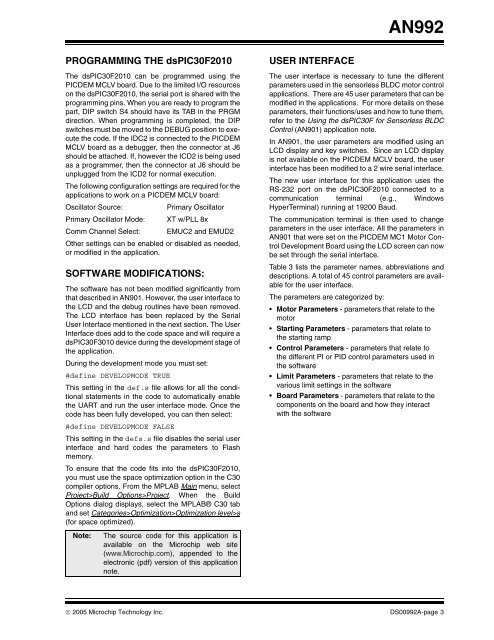
AN992PROGRAMMING THE <strong>dsPIC30F2010</strong>The <strong>dsPIC30F2010</strong> can be programmed using thePICDEM MCLV board. Due to the limited I/O resourceson the <strong>dsPIC30F2010</strong>, the serial port is shared with theprogramming pins. When you are ready to program thepart, DIP switch S4 should have its TAB in the PRGMdirection. When programming is completed, the DIPswitches must be moved to the DEBUG position to executethe code. If the IDC2 is connected to the PICDEMMCLV board as a debugger, then the connector at J6should be attached. If, however the ICD2 is being usedas a programmer, then the connector at J6 should beunplugged from the ICD2 for normal execution.The following configuration settings are required for theapplications to work on a PICDEM MCLV board:Oscillator Source:Primary OscillatorPrimary Oscillator Mode: XT w/PLL 8xComm Channel Select: EMUC2 and EMUD2Other settings can be enabled or disabled as needed,or modified in the application.SOFTWARE MODIFICATIONS:The software has not been modified significantly fromthat described in AN901. However, the user interface tothe LCD and the debug routines have been removed.The LCD interface has been replaced by the SerialUser Interface mentioned in the next section. The UserInterface does add to the code space and will require adsPIC30F3010 device during the development stage ofthe application.During the development mode you must set:#define DEVELOPMODE TRUEThis setting in the def.s file allows for all the conditionalstatements in the code to automatically enablethe UART and run the user interface mode. Once thecode has been fully developed, you can then select:#define DEVELOPMODE FALSEThis setting in the defs.s file disables the serial userinterface and hard codes the parameters to Flashmemory.To ensure that the code fits into the <strong>dsPIC30F2010</strong>,you must use the space optimization option in the C30compiler options. From the MPLAB Main menu, selectProject>Build Options>Project. When the BuildOptions dialog displays, select the MPLAB® C30 taband set Categories>Optimization>Optimization level>s(for space optimized).Note:The source code for this application isavailable on the Microchip web site(www.Microchip.com), appended to theelectronic (pdf) version of this applicationnote.USER INTERFACEThe user interface is necessary to tune the differentparameters used in the sensorless <strong>BLDC</strong> motor controlapplications. There are 45 user parameters that can bemodified in the applications. For more details on theseparameters, their functions/uses and how to tune them,refer to the <strong>Using</strong> the dsPIC30F for <strong>Sensorless</strong> <strong>BLDC</strong><strong>Control</strong> (AN901) application note.In AN901, the user parameters are modified using anLCD display and key switches. Since an LCD displayis not available on the PICDEM MCLV board, the userinterface has been modified to a 2 wire serial interface.The new user interface for this application uses theRS-232 port on the <strong>dsPIC30F2010</strong> connected to acommunication terminal (e.g., WindowsHyperTerminal) running at 19200 Baud.The communication terminal is then used to changeparameters in the user interface. All the parameters inAN901 that were set on the PICDEM MC1 <strong>Motor</strong> <strong>Control</strong>Development Board using the LCD screen can nowbe set through the serial interface.Table 3 lists the parameter names, abbreviations anddescriptions. A total of 45 control parameters are availablefor the user interface.The parameters are categorized by:• <strong>Motor</strong> Parameters - parameters that relate to themotor• Starting Parameters - parameters that relate tothe starting ramp• <strong>Control</strong> Parameters - parameters that relate tothe different PI or PID control parameters used inthe software• Limit Parameters - parameters that relate to thevarious limit settings in the software• Board Parameters - parameters that relate to thecomponents on the board and how they interactwith the software© 2005 Microchip Technology Inc. DS00992A-page 3