FCB-RS Interface Board for Sony Cameras Connector and Pin ...
FCB-RS Interface Board for Sony Cameras Connector and Pin ...
FCB-RS Interface Board for Sony Cameras Connector and Pin ...

You also want an ePaper? Increase the reach of your titles
YUMPU automatically turns print PDFs into web optimized ePapers that Google loves.
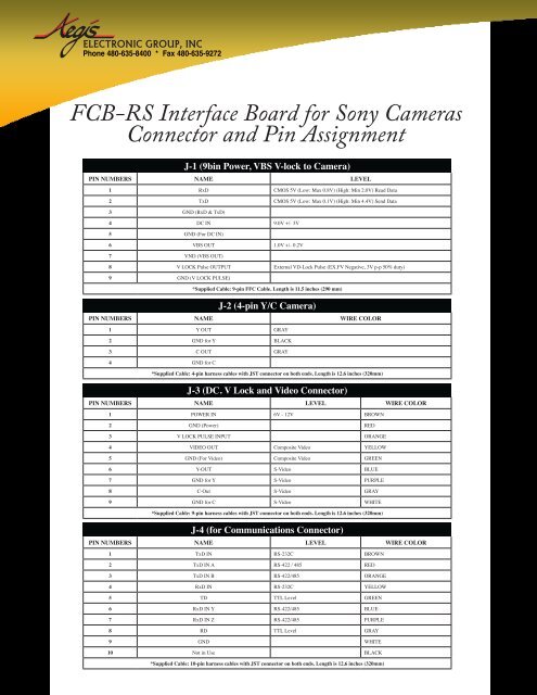
Phone 480-635-8400 * Fax 480-635-9272<strong>FCB</strong>-<strong>RS</strong> <strong>Interface</strong> <strong>Board</strong> <strong>for</strong> <strong>Sony</strong> <strong>Cameras</strong><strong>Connector</strong> <strong>and</strong> <strong>Pin</strong> AssignmentJ-1 (9bin Power, VBS V-lock to Camera)PIN NUMBE<strong>RS</strong> NAME LEVEL1 RxD CMOS 5V (Low: Max 0.8V) (High: Min 2.0V) Read Data2 TxD CMOS 5V (Low: Max 0.1V) (High: Min 4.4V) Send Data3 GND (RxD & TxD)4 DC IN 9.0V +/- 3V5 GND (For DC IN)6 VBS OUT 1.0V +/- 0.2V7 VND (VBS OUT)8 V LOCK Pulse OUTPUT External VD-Lock Pulse (EX.FV Negative, 3V p-p 50% duty)9 GND (V LOCK PULSE)*Supplied Cable: 9-pin FFC Cable. Length is 11.5 inches (290 mm)J-2 (4-pin Y/C Camera)PIN NUMBE<strong>RS</strong> NAME WIRE COLOR1 Y OUT GRAY2 GND <strong>for</strong> Y BLACK3 C OUT GRAY4 GND <strong>for</strong> C*Supplied Cable: 4-pin harness cables with JST connector on both ends. Length is 12.6 inches (320mm)J-3 (DC. V Lock <strong>and</strong> Video <strong>Connector</strong>)PIN NUMBE<strong>RS</strong> NAME LEVEL WIRE COLOR1 POWER IN 6V - 12V BROWN2 GND (Power) RED3 V LOCK PULSE INPUT ORANGE4 VIDEO OUT Composite Video YELLOW5 GND (For Video) Composite Video GREEN6 Y-OUT S-Video BLUE7 GND <strong>for</strong> Y S-Video PURPLE8 C-Out S-Video GRAY9 GND <strong>for</strong> C S-Video WHITE*Supplied Cable: 9-pin harness cables with JST connector on both ends. Length is 12.6 inches (320mm)J-4 (<strong>for</strong> Communications <strong>Connector</strong>)PIN NUMBE<strong>RS</strong> NAME LEVEL WIRE COLOR1 TxD IN <strong>RS</strong>-232C BROWN2 TxD IN A <strong>RS</strong>-422 / 485 RED3 TxD IN B <strong>RS</strong>-422/485 ORANGE4 RxD IN <strong>RS</strong>-232C YELLOW5 TD TTL Level GREEN6 RxD IN Y <strong>RS</strong>-422/485 BLUE7 RxD IN Z <strong>RS</strong>-422/485 PURPLE8 RD TTL Level GRAY9 GND WHITE10 Not in Use BLACK*Supplied Cable: 10-pin harness cables with JST connector on both ends. Length is 12.6 inches (320mm)
To select the Serial / Communication level, use the following table to the dip switchesFor “ON” “OFF”<strong>RS</strong>232 1, 2 3, 4, 5, 6TTL Direct 3, 4 1, 2, 5, 6<strong>RS</strong>422/485 5, 6 1, 2, 3, 4For <strong>RS</strong>422 JUMP 1 may be removed <strong>for</strong> use with multiple camerasPhone: 480-635-8400 * Fax: 480-635-9272 * aegis-g2@aegiselect.com * http://www.aegis-elec.com