FCB-RS Interface Board for Sony Cameras Connector and Pin ...
FCB-RS Interface Board for Sony Cameras Connector and Pin ...
FCB-RS Interface Board for Sony Cameras Connector and Pin ...

Create successful ePaper yourself
Turn your PDF publications into a flip-book with our unique Google optimized e-Paper software.
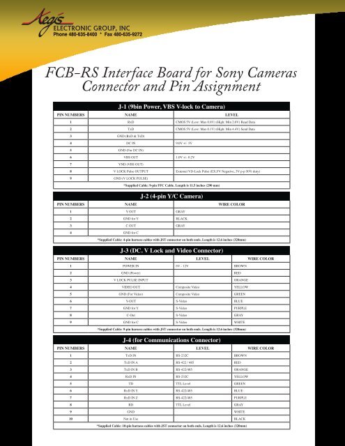
Phone 480-635-8400 * Fax 480-635-9272<strong>FCB</strong>-<strong>RS</strong> <strong>Interface</strong> <strong>Board</strong> <strong>for</strong> <strong>Sony</strong> <strong>Cameras</strong><strong>Connector</strong> <strong>and</strong> <strong>Pin</strong> AssignmentJ-1 (9bin Power, VBS V-lock to Camera)PIN NUMBE<strong>RS</strong> NAME LEVEL1 RxD CMOS 5V (Low: Max 0.8V) (High: Min 2.0V) Read Data2 TxD CMOS 5V (Low: Max 0.1V) (High: Min 4.4V) Send Data3 GND (RxD & TxD)4 DC IN 9.0V +/- 3V5 GND (For DC IN)6 VBS OUT 1.0V +/- 0.2V7 VND (VBS OUT)8 V LOCK Pulse OUTPUT External VD-Lock Pulse (EX.FV Negative, 3V p-p 50% duty)9 GND (V LOCK PULSE)*Supplied Cable: 9-pin FFC Cable. Length is 11.5 inches (290 mm)J-2 (4-pin Y/C Camera)PIN NUMBE<strong>RS</strong> NAME WIRE COLOR1 Y OUT GRAY2 GND <strong>for</strong> Y BLACK3 C OUT GRAY4 GND <strong>for</strong> C*Supplied Cable: 4-pin harness cables with JST connector on both ends. Length is 12.6 inches (320mm)J-3 (DC. V Lock <strong>and</strong> Video <strong>Connector</strong>)PIN NUMBE<strong>RS</strong> NAME LEVEL WIRE COLOR1 POWER IN 6V - 12V BROWN2 GND (Power) RED3 V LOCK PULSE INPUT ORANGE4 VIDEO OUT Composite Video YELLOW5 GND (For Video) Composite Video GREEN6 Y-OUT S-Video BLUE7 GND <strong>for</strong> Y S-Video PURPLE8 C-Out S-Video GRAY9 GND <strong>for</strong> C S-Video WHITE*Supplied Cable: 9-pin harness cables with JST connector on both ends. Length is 12.6 inches (320mm)J-4 (<strong>for</strong> Communications <strong>Connector</strong>)PIN NUMBE<strong>RS</strong> NAME LEVEL WIRE COLOR1 TxD IN <strong>RS</strong>-232C BROWN2 TxD IN A <strong>RS</strong>-422 / 485 RED3 TxD IN B <strong>RS</strong>-422/485 ORANGE4 RxD IN <strong>RS</strong>-232C YELLOW5 TD TTL Level GREEN6 RxD IN Y <strong>RS</strong>-422/485 BLUE7 RxD IN Z <strong>RS</strong>-422/485 PURPLE8 RD TTL Level GRAY9 GND WHITE10 Not in Use BLACK*Supplied Cable: 10-pin harness cables with JST connector on both ends. Length is 12.6 inches (320mm)
To select the Serial / Communication level, use the following table to the dip switchesFor “ON” “OFF”<strong>RS</strong>232 1, 2 3, 4, 5, 6TTL Direct 3, 4 1, 2, 5, 6<strong>RS</strong>422/485 5, 6 1, 2, 3, 4For <strong>RS</strong>422 JUMP 1 may be removed <strong>for</strong> use with multiple camerasPhone: 480-635-8400 * Fax: 480-635-9272 * aegis-g2@aegiselect.com * http://www.aegis-elec.com