CYMFLOW - Power Flow Analysis - Cyme International
CYMFLOW - Power Flow Analysis - Cyme International
CYMFLOW - Power Flow Analysis - Cyme International

You also want an ePaper? Increase the reach of your titles
YUMPU automatically turns print PDFs into web optimized ePapers that Google loves.
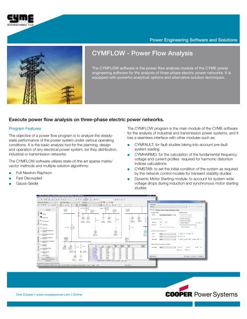
<strong>Power</strong> Engineering Software and Solutions<strong>CYMFLOW</strong> - <strong>Power</strong> <strong>Flow</strong> <strong>Analysis</strong>The <strong>CYMFLOW</strong> software is the power flow analysis module of the CYME powerengineering software for the analysis of three-phase electric power networks. It isequipped with powerful analytical options and alternative solution techniques.Execute power flow analysis on three-phase electric power networks.Program FeaturesThe objective of a power flow program is to analyze the steadystateperformance of the power system under various operatingconditions. It is the basic analysis tool for the planning, designand operation of any electrical power system, be they distribution,industrial or transmission networks.The <strong>CYMFLOW</strong> software utilizes state-of-the-art sparse matrix/vector methods and multiple solution algorithms:■■■■■■Full Newton-RaphsonFast DecoupledGauss-SeidelThe <strong>CYMFLOW</strong> program is the main module of the CYME softwarefor the analysis of industrial and transmission power systems, and ithas a seamless interface with other modules such as:■■■■■■■■CYMFAULT: for fault studies taking into account pre-faultsystem loadingCYMHARMO: for the calculation of the fundamental frequencyvoltage and current profiles required for harmonic distortionindices calculationsCYMSTAB: to set the initial condition of the system as requiredby the network control models for transient stability studiesDynamic Motor Starting module: to account for system widevoltage drops during induction and synchronous motor startingstudiesOne Cooper | www.cooperpower.com | Online
<strong>CYMFLOW</strong> - <strong>Power</strong> <strong>Flow</strong><strong>Analysis</strong>Execute power flow analysis on three-phaseelectric power networks.Analytical Capabilities■■■■■■■■■■■■■■■■■■■■Analyzes networks with thousands ofbuses and branchesMultiple swing buses allowedAutomatic swing bus selection forisolated subsystemsSimultaneous solution for islandednetworksDetailed equipment modeling ofinduction and synchronous motors,variable frequency drives, bus waysand all necessary network elementsfor an accurate representation of thenetworkSynchronous generator• Reactive power limits and remotevoltage control• Generator reactive power capabilitycurvesLocal or remote control of voltageand reactive power flow through tapchanging transformersPhase angle shift transformer withactive power controlCogeneration modeling including:• Induction generators• Wind Energy Conversion Systems(WECS)• Photovoltaic (PV Cells)• Fuel cells• Micro-turbinesComprehensive representation of DCtransmission lines with rectifier andinverter controls■■■■■■■■■■■■■■■■Flexible AC Transmission Systems(FACTS) representation of:• Static synchronous compensator(STATCOM),• Unified <strong>Power</strong> <strong>Flow</strong> Controller(UPFC)Customer load model library managerfor any type of load model including:• Constant power, constant currentand constant impedance• Composite load model• Voltage sensitivity exponent loadmodelCapacitors with the following controltypes: voltage, current, reactivecurrent, reactive power, power factor,temperature and time-controlledSwitchable shunt banks of bothcapacitive and inductive elementsScaling factors applied to thegenerators and to the loads on thewhole network or by zoneGlobal parameters to include orexclude any types of equipment fromthe analysisFive limit categories for nominal,planning, emergency loading or anyuser-defined criteriaUser-defined units for bus voltages,generator productions and branchflows on both one-line diagrams andtabular reports■■■■Tabular reports can also be directlyexported to other spreadsheetprograms such as Microsoft Excel®Color coding on the network one-linediagram as per user-defined criteria; forexample:• Overloaded equipment• Voltage violations of buses andnodes• Visualization of conductor rating thatmay reflect, for example, improperlysized cables• System voltage levelsGenerator Capability Curves<strong>Power</strong> Electronics - FACTS<strong>Power</strong> Electronics - DC SystemsCYME <strong>International</strong>1485 Roberval, Suite 104St-Bruno, QC Canada J3V 3P8P: 450.461.3655F: 450.461.0966P: 800.361.3627 (Canada/USA)www.cyme.cominfo@cyme.comOne Cooper | www.cooperpower.com | OnlineB1170-12032 • 1012Cooper <strong>Power</strong> Systems, CYME and all CYME module names are valuable trademarks of Cooper Industries in the U.S. and othercountries. You are not permitted to use the Cooper Trademarks without the prior written consent of Cooper Industries.©2012 Cooper Industries. All Rights Reserved.