Safety Control Unit SG-EFS 1X4 ZK2/1 L20ms Operating Instructions
Safety Control Unit SG-EFS 1X4 ZK2/1 L20ms Operating Instructions
Safety Control Unit SG-EFS 1X4 ZK2/1 L20ms Operating Instructions

Create successful ePaper yourself
Turn your PDF publications into a flip-book with our unique Google optimized e-Paper software.
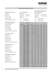
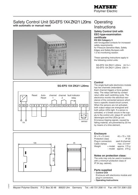
<strong>Safety</strong> <strong>Control</strong> <strong>Unit</strong> <strong>SG</strong>-<strong>EFS</strong> <strong>1X4</strong> <strong>ZK2</strong>/1 8k2IMPORTANT NOTES!Please read!To ensure correct and safe operationof the unit, it must be properly transportedand stored, properly installedand commissioned, and operated inaccordance with its purpose.Only persons familiar with the installation,commissioning and operation,and with the corresponding qualificationsto prove their skills, may work onthe units. They must observe the contentsof these instructions, the notesgiven on the type plate of the unit andthe safety requirements relevant to theinstallation and operation of electricalsystems.This unit is constructed and tested toprEN 1760 and DIN V 31006 and left ourfactory in perfect condition with regardto safety. In order to maintain this state,you must observe the safety regulationsmarked "WARNING!" in these operatinginstructions. Failure to observe the safetyregulations can lead to death, injuryto personnel, or damage to the unit andother systems and equipment.Should the information given in theseoperating instructions be inadequatein any way, please contact your localtechnical centre, subsidiary or representative.When using the device outside theEuropean Union, you must observethe relevant regulations valid for thecountry of use.2 connection variants:- <strong>SG</strong>-<strong>EFS</strong> <strong>1X4</strong> <strong>ZK2</strong>/1 <strong>L20ms</strong>with automatic resetBridge 7, 8 must be in placeThe unit becomes active again assoon as the sensor is no longeractivated.The fault indicator relay K3 works insynchrony with the sa fety relays K1,K2 and is available as a voltage free,normally closed contact.- <strong>SG</strong>-<strong>EFS</strong> <strong>1X4</strong> <strong>ZK2</strong>/1 <strong>L20ms</strong>with manual resetBridge 7, 8 must be removedAfter deactivation of the unit by thesensor it must be re-activated bymeans of an external reset button.The fault indicator relay K3 works insynchrony with the safety relays K1,K2 and is available as a voltage free,normally closed contact.WARNING!Not for safety circuit:- The fault indicator contact across 31,32 is solely for information purposesand must not be connected into thesafety circuit.Do not cross link controlunits:- Clamps 5, 6 as well as 7, 8 and Y1,Y2 are not voltage free and thusmay not be cross linked with furthercontrol units.Technical DataConnecting voltage U S<strong>SG</strong>-<strong>EFS</strong> 104 <strong>ZK2</strong>/1 <strong>L20ms</strong> AC 24 V DC 24 V<strong>SG</strong>-<strong>EFS</strong> 134 <strong>ZK2</strong>/1 <strong>L20ms</strong> AC 230 VVoltage tolerance -15% to +10% -15% to +20%Nominal frequency50 HzFrequency tolerance48 - 62 HzPower consumption < 5 VA for AC < 5 W for DC 28 VSensor voltageDC 15 V<strong>Control</strong> <strong>Unit</strong> OutputsSwitching channel K1 and K2 11/14, 21/24Switching voltage max. AC 240 V max. DC 24 VSwitching current 4 A 1 AFault indicator relay K3 31/32Switching voltage max. AC 42 V max. DC 42 VSwitching current max.100 mA max. 100 mAPermissible ambient temp. -20 °C to +50 °CNote:When switching inductive loads theuser must be fitted out with spark absorbers.Mayser Polymer Electric P.O. Box 30 48 89020 Ulm Germany Tel. +49 731 2061-0 Fax +49 731 2061-222110707
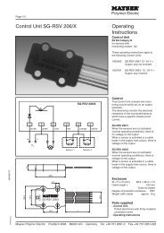
Installation and OperationKanal1Kanal2SignalgeberEIN0.1AAuto-Reset ResetNetzspannung U ssieheLeistungsschildInstallationThe enclosure of the control unit can bemounted in any position:- on a 35 mm EN 50022 railWiring is carried out in the cable clampsof the plug-in connection:SensorY1, Y2Supply voltage A1, A2Switching channel K1 11,1 4Switching channel K2 21, 24Fault indicator relay 31, 32Reset button 5, 6for automatice reset only:Bridge 7, 8CommissioningAfter connecting up sensors, switchingcontacts and power, carry out a functiontest in the following order:Sensor not activated- both yellow LEDs light- outpit relays K1, K2 are energized- fault indicator relay K3 is energizedActivate sensor- both yellow LEDs go out- output relays K1, K2 deenergize- fault indicator relay K3 deenergizesWARNING!Do not release terminals or removethe plug-in connection with poweron.contacts continued intwo-channel modechannel 1 channel 2Important notes:- Supply voltagemust be in accordance with the connectingvoltage U Sindicated on thetype plate.- Permissible temperature rangeIf installing into a cabinet, maintainsufficient distance from heat sources(min. 2 cm).- WiringWire direct to the control circuit orcontinue two-channel mode to thenext circuit.Fuse the relay contacts externally (riskof welding).MaintenanceThe control unit is maintenance-free.Check the safety installation monthly byactivating the sensors.contact duplicationfor automatic resetcontact duplicationfor manual resetchannel1channel2channel 1 channel 2RESET110707Mayser Polymer Electric P.O. Box 30 48 89020 Ulm Germany Tel. +49 731 2061-0 Fax +49 731 2061-222
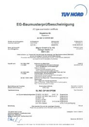
Check sensorsensorcontrolunitCheck combinationof sensorsResistance measurement:Disconnect power to the unit.Unplug plug-in connection and measure(Y1,Y2) with an ohmmeter:not activated c. 1.2 kΩactivated < 150 ΩIf the values measured deviate considerablyfrom the set values, the sensorshave to be checked individually (seebelow)./BK /WCheck individual sensorsResistance measurement:Measure each individual sensor with anohmmeter:/BK not activated infinite Ωactivated < 150 Ω/W not activated c. 1.2 kΩactivated < 150 ΩCheck also cables and cable connections.Damaged or faulty sensors must berepaired or replaced immediately by aspecialist.Only a functioning system can ensuremaximum safety!Troubleshooting and remediesPrerequisite: <strong>SG</strong>-<strong>EFS</strong> connected to power supply, sensor not activated.yellow LEDs do not light, relay K1 and K2 are deenergized:> supply voltage off or incorrect Check supply voltage, compare with type plate.> Faulty sensor or supply lines (break in connection or short circuit) Connect 1.2 kΩ resistor instead of sensor. If the yellow LEDs do not light, thecontrol unit is faulty. Replace control unit.one yellow LED lights:> fault in control unit <strong>Control</strong> unit faulty. Replace control unit.Problem not solved? – The MayserSupport Team can help: tel. +49 7312061-0Subject to technical modifications.Mayser Polymer Electric P.O. Box 30 48 89020 Ulm Germany Tel. +49 731 2061-0 Fax +49 731 2061-222110707