Instructions And Parts Manual 10-inch Cabinet Saw - Powermatic
Instructions And Parts Manual 10-inch Cabinet Saw - Powermatic
Instructions And Parts Manual 10-inch Cabinet Saw - Powermatic

Create successful ePaper yourself
Turn your PDF publications into a flip-book with our unique Google optimized e-Paper software.
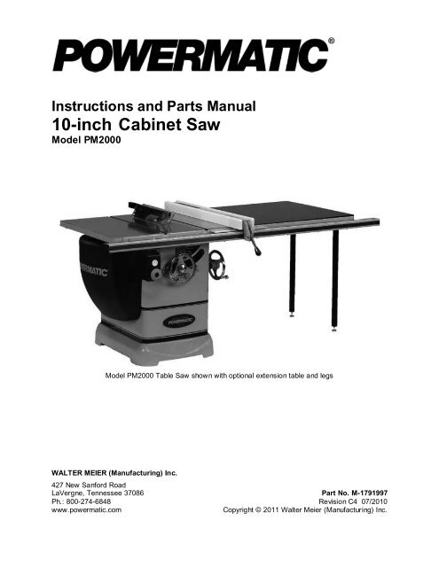
<strong>Instructions</strong> and <strong>Parts</strong> <strong>Manual</strong><strong>10</strong>-<strong>inch</strong> <strong>Cabinet</strong> <strong>Saw</strong>Model PM2000Model PM2000 Table <strong>Saw</strong> shown with optional extension table and legsWALTER MEIER (Manufacturing) Inc.427 New Sanford RoadLaVergne, Tennessee 37086 Part No. M-1791997Ph.: 800-274-6848 Revision C4 07/20<strong>10</strong>www.powermatic.comCopyright © 2011 Walter Meier (Manufacturing) Inc.
Table of ContentsWarranty and Service..........................................................................................................................2Table of Contents ...............................................................................................................................3Warnings............................................................................................................................................4Introduction ........................................................................................................................................6Specifications .....................................................................................................................................6Shipping Contents ..............................................................................................................................7Unpacking ......................................................................................................................................7Cleaning .........................................................................................................................................7Contents of the Shipping Container ..................................................................................................8Assembly ......................................................................................................................................... <strong>10</strong>Mounting Extension Wings ............................................................................................................. <strong>10</strong>Lock Knobs and Swivel Handles..................................................................................................... 11Dust Chute.................................................................................................................................... 11Blade Installation/Replacement ...................................................................................................... 12Mounting Rails and Accu-Fence ® ................................................................................................... 12Optional Wood Extension Table ..................................................................................................... 12Switch Installation.......................................................................................................................... 12Riving Knife and Guard Installation ................................................................................................. 13Grounding <strong>Instructions</strong> ...................................................................................................................... 14Extension Cords ............................................................................................................................ 14Zero-Clearance Insert Setup .......................................................................................................... 15Miter Slot Alignment ...................................................................................................................... 16Tilt Stop Adjustment ...................................................................................................................... 16Precision Miter Gauge ................................................................................................................... 17Riving Knife Adjustment ................................................................................................................. 18Insert Adjustment .......................................................................................................................... 19Arbor and Arbor Bearing Removal .................................................................................................. 19Operating Controls............................................................................................................................ 20Start/Stop ..................................................................................................................................... 20Safety Key .................................................................................................................................... 20Motor Cover .................................................................................................................................. 12Adjustments ..................................................................................................................................... 14Handwheel Adjustments ................................................................................................................ 14Drive Belt ...................................................................................................................................... 17Operations ....................................................................................................................................... 21Overview ...................................................................................................................................... 21Kickback ....................................................................................................................................... 21Bevel and Miter Operations ............................................................................................................ 24Safety Devices ................................................................................................................................. 25Feather Board and Push Blocks ..................................................................................................... 25Push Stick..................................................................................................................................... 25Filler Piece .................................................................................................................................... 25Maintenance .................................................................................................................................... 26Cleaning ....................................................................................................................................... 26Lubrication .................................................................................................................................... 26Miscellaneous ............................................................................................................................... 26Troubleshooting ................................................................................................................................ 27Optional Accessories ........................................................................................................................ 28Ordering Replacement <strong>Parts</strong> .......................................................................................................... 28Model PM2000 Table <strong>Saw</strong> <strong>Parts</strong> List .................................................................................................. 29Wiring Diagrams ............................................................................................................................... 38The specifications in this manual are given as general information and are not binding. Walter Meier(Manufacturing) Inc., reserves the right to effect, at any time and without prior notice, changes oralterations to parts, fittings, and accessory equipment deemed necessary for any reason whatsoever.3
Warnings1. Read and understand the entire owner’s manual before attempting assembly or operation.2. Read and understand the warnings posted on the machine and in this manual. Failure to comply withall of these warnings may cause serious injury.3. Replace the warning labels if they become obscured or removed.4. This table saw is designed and intended for use by properly trained and experienced personnel only.If you are not familiar with the proper and safe operation of a table saw, do not use until propertraining and knowledge have been obtained.5. Do not use this table saw for other than its intended use. If used for other purposes, Walter Meier(Manufacturing) Inc., disclaims any real or implied warranty and holds itself harmless from any injurythat may result from that use.6. Always wear approved safety glasses/face shields while using this table saw. Everyday eyeglassesonly have impact resistant lenses; they are not safety glasses.7. Before operating this table saw, remove tie, rings, watches and other jewelry, and roll sleeves up pastthe elbows. Remove all loose clothing and confine long hair. Non-slip footwear or anti-skid floor stripsare recommended. Do not wear gloves.8. Wear ear protectors (plugs or muffs) during extended periods of operation.9. Some dust created by power sanding, sawing, grinding, drilling and other construction activitiescontain chemicals known to cause cancer, birth defects or other reproductive harm. Some examplesof these chemicals are:• Lead from lead based paint.• Crystalline silica from bricks, cement and other masonry products.• Arsenic and chromium from chemically treated lumber.Your risk of exposure varies, depending on how often you do this type of work. To reduce yourexposure to these chemicals, work in a well-ventilated area and work with approved safetyequipment, such as face or dust masks that are specifically designed to filter out microscopicparticles.<strong>10</strong>. Do not operate this machine while tired or under the influence of drugs, alcohol or any medication.11. Make certain the machine is properly grounded.12. Make all machine adjustments or maintenance with the machine unplugged from the power source. Amachine under repair should be RED TAGGED to show it must not be used until maintenance iscomplete.13. Remove adjusting keys and wrenches. Form a habit of checking to see that keys and adjustingwrenches are removed from the machine before turning it on.14. Keep safety guards in place at all times when the machine is in use. If removed for maintenancepurposes, use extreme caution and replace the guards immediately.15. Check the alignment of the riving knife, fence and miter slot to the blade. A caution decal is installedon each guard to remind the operator of the dangers of improper machine operation.16. Check damaged parts. Before further use of the machine, a guard or other part that is damagedshould be carefully checked to determine that it will operate properly and perform its intendedfunction. Check for alignment of moving parts, binding of moving parts, breakage of parts, mountingand any other conditions that may affect its operation. A guard or other part that is damaged shouldbe properly repaired or replaced.4
17. Provide for adequate space surrounding work area and non-glare, overhead lighting.18. Keep the floor around the machine clean and free of scrap material, oil and grease.19. Keep visitors a safe distance from the work area. Keep children away.20. Make your workshop child proof with padlocks, master switches or by removing safety keys.21. Give your work undivided attention. Looking around, carrying on a conversation and “horse-play” arecareless acts that can result in serious injury.22. Maintain a balanced stance at all times so that you do not fall or lean against the blade or othermoving parts. Do not overreach or use excessive force to perform any machine operation.23. Use the right tool at the correct speed and feed rate. Do not force a tool or attachment to do a job forwhich it was not designed. The right tool will do the job better and safer.24. Use recommended accessories; improper accessories may be hazardous.25. Maintain tools with care. Keep blade sharp and clean for the best and safest performance. Followinstructions for lubricating and changing accessories.26. Check the saw blade for cracks or missing teeth. Do not use a cracked or dull blade or one withmissing teeth or improper set. Make sure the blade is securely locked on the arbor.27. Keep hands clear of the blade area. Do not reach past the blade to clear parts or scrap with the sawblade running. Never saw freehand. Avoid awkward operations and hand positions where a suddenslip could cause your hand to contact the blade.28. Do not attempt to saw boards with loose knots or with nails or other foreign material, on its surface.Do not attempt to saw twisted, warped, bowed or “in wind” stock unless one edge has been jointed forguiding purposes prior to sawing.29. Do not attempt to saw long or wide boards unsupported where spring or weight could cause theboard to shift position.30. Always use the riving knife, blade guard, push stick and other safety devices for all operations wherethey can be used. On operations such as dadoing or molding where the blade guard cannot be used,use feather boards, fixtures and other safety devices and use extreme caution. Reinstall the rivingknife and blade guard immediately after completing the operation that required their removal.31. Be sure the saw blade rotates clockwise when viewed from the motor side (left side) of the machine.32. Turn off the machine before cleaning. Use a brush or compressed air to remove chips or debris — donot use your hands.33. Do not stand on the machine. Serious injury could occur if the machine tips over.34. Never leave the machine running unattended. Turn the power off and do not leave the machine until itcomes to a complete stop.35. Remove loose items and unnecessary work pieces from the area before starting the machine.Familiarize yourself with the following safety notices used in this manual:This means that if precautions are not heeded, it may result in minor injury and/orpossible machine damage.even death.This means that if precautions are not heeded, it may result in serious injury or possibly5
IntroductionThis manual is provided by Walter Meier (Manufacturing) Inc., covering the safe operation andmaintenance procedures for a <strong>Powermatic</strong> Model PM2000 Table <strong>Saw</strong>. This manual contains instructionson installation, safety precautions, general operating procedures, maintenance instructions and partsbreakdown. This machine has been designed and constructed to provide years of trouble free operation ifused in accordance with instructions set forth in this manual. If there are any questions or comments,please contact either your local supplier or Walter Meier. Walter Meier can also be reached at our website: www.wmhtoolgroup.com.SpecificationsModel number ......................................................................................................................... PM2000Stock Number3HP, 230V, 60Hz, 1 Phase, 3600 RPM, TEFC ......................................................................17919995HP, 230V, 60Hz, 1 Phase, 3600 RPM, TEFC ......................................................................17919985HP, Prewired 230V (for 460V see Note below), 60Hz, 3 Phase, 3600 RPM, TEFC ................1791997Table size with standard extensions (L x W/in.)...................................................................... 42 x 30 1/2Table size without extensions (L x W/in.) ............................................................................... 22 x 30 1/2Arbor diameter (in.) .......................................................................................................................... 5/8<strong>Saw</strong> blade diameter (in.) ................................................................................................................... <strong>10</strong>Arbor speed (RPM) ....................................................................................................................... 4300Left tilt range ................................................................................................................................ 0–45Maximum depth of cut (in.) ........................................................3-1/8 at 90-degrees; 2-1/8 at 45-degreesMaximum diameter of dado (in.)........................................................................................................... 8Maximum width of dado cut (in.) ................................................................................................... 13/16Drive system ....................................................................................................................... Poly-V BeltTable height to floor (in.) ............................................................................................................. 34-1/2Dust port diameter (in.) ....................................................................................................................... 4Shipping weight (saw only) ......................................................... All Models: Net: 540 lbs, Gross: 604 lbsNote: For 460V operation, magnetic switch (Part No. PM2000-293C) must be purchased separately andinstalled. A qualified electrician is recommended.The above specifications were current at the time this manual was published, but because of our policy ofcontinuous improvement, Walter Meier reserves the right to change specifications at any time and withoutprior notice, without incurring obligations.Read and understand the entire contents of this manual before attemptingassembly or operation! Failure to comply may cause serious injury6
Shipping ContentsUnpackingRemove box and wood crating completely fromaround saw. Check for shipping damage. Reportany damage immediately to your distributor andshipping agent. Do not discard any shippingmaterial until the Table <strong>Saw</strong> is assembled andrunning properly.Compare the contents of your container with theparts lists in the next two pages to make sure allparts are intact. Missing parts, if any, should bereported to your distributor. Read the instructionmanual thoroughly for assembly, maintenanceand safety instructions.1. Unbolt the saw from the skid.2. Carefully slide the saw from the pallet ontothe floor.Make sure that the castors donot get damaged when removing from theskid.The Table <strong>Saw</strong> should be placed in an area witha sturdy level floor, good ventilation andsufficient lighting. Leave enough space aroundthe machine for mounting extension wings andrail assemblies, and loading and off-loadingstock and general maintenance work.CleaningExposed metal surfaces, such as the table topand extension wings, have been given aprotective coating at the factory. This should beremoved with a soft cloth moistened withkerosene. Do not use acetone, gasoline, orlacquer thinner for this purpose. Do not usesolvents on plastic parts, and do not use anabrasive pad because it may scratch thesurfaces.7
Contents of the Shipping ContainerMain <strong>Saw</strong> Container1 Table <strong>Saw</strong> (A)1 Table Insert (B)The following items are inside the saw:1 Miter Gauge Assembly (C)1 Blade Guard Assembly (D)1 Switch in box (E)1 Owner's <strong>Manual</strong> (F)1 Warranty Card (not shown)Small BoxThe small box consists of the following items:1 Push Stick (G)1 27mm Arbor Wrench (H)2 Lock Knobs (J)2 Swivel Handles (K)1 Riving Knife and Pawl Assembly (L)1 Low Profile Riving Knife (M)1 Hardware Bag (N) consisting of:6 3/8-16 x 1 Hex Cap Screw (AA)6 3/8 Lock Washer (BB)6 3/8 Flat Washer (CC)Main <strong>Saw</strong> ContainerContents of the Small Box8
Extension TablesTwo extension tables are packaged in individualboxes.Extension TablesSide Cover Box2 Hinge Pin (N)1 Side Cover (O)Contents of Side Cover BoxFence and RailCarton contents and installation instructions for thefence, rail system, and optional wooden extensiontable are described in the Accu-Fence Owner's<strong>Manual</strong> (No. M-2195079Z).9
AssemblyMounting Extension WingsReferring to Figure 1:1. Mount a cast iron extension wing (A) to theright or left side of the table (B) using threeeach 3/8-16x1 hex head screws (C), 3/8 lockwashers (D) and 3/8 flat washers (E). Have anassistant hold the extension wing up to thetable while inserting the screws and washers.Finger-tighten only.Note: If an assistant is not available, hold thewing in vertical position up to the saw table,insert the middle screw and lock washer fingertight, then pivot the wing to level position. Insertthe other two screws and washers finger tight.2. Mount the remaining extension wing to theother side of the table in the same manner.Figure 13. Make sure that the front edge of the extensionwings are flush with the front edge of saw table(Figure 2).Figure 24. Level the extension wing with the saw tableacross its entire width (Figure 3) using astraight edge and hammer with block of wood(or rubber hammer).As each area of the wing becomes flush withthe table, tighten the screw under that area.Continue until all three screws are fullytightened.5. Repeat for the other extension wing.Figure 3<strong>10</strong>
Lock Knobs and Swivel HandlesReferring to Figure 4:1. Thread the swivel handles (A) into the front andside handwheels (C) and tighten with a 14mmwrench.2. Screw lock knobs (B) into the threadedopenings on the end of the shafts located in themiddle of the handwheels (C).Note: Do not tighten the lock knobs all the wayat this time.Figure 4Dust ChuteReferring to Figure 5:The Model 2000 comes equipped with a dust chuteand hose assembly (Inset 2) for use with a dustcollection system. If you do not intend to use a dustcollection system, the dust chute may bedisconnected and removed as described below.To provide sufficient clearance for removal of thedust chute:1. Raise the blade height all the way up and setthe blade tilt to 0º (refer to HandwheelAdjustments on page 14).2. Remove the arbor nut and collar as describedin the Blade Installation/Replacement on page12, steps 3-4.Removing the dust chute:3. Remove two socket head button screws (D, E)with 4mm and 5mm hex wrenches respectively.4. Through the opening on the left side of thecabinet, remove the hose (Inset 1, 2) bytwisting and pulling back on the dust port (F).Take the entire assembly (Inset 2) out throughthe side opening.Do not replace the arbor nut and collar at this time,but proceed to the Blade Installation/Replacementsection (following page).Figure 511
Blade Installation/ReplacementUse care when working with oraround sharp saw blade to prevent injury!To install or replace a blade (refer to Figure 6):1. Disconnect machine from power source.2. Raise the blade height all the way up and setthe blade tilt to 0º (refer to HandwheelAdjustments on page 14).3. Press the arbor lock (D) in the direction shownby the arrow to engage it into the slot in thearbor (C). At the same time remove the arbornut (loosen with a 27mm wrench if necessary).4. Remove the collar (B).5. Install the blade, making sure the cutting teethat the top of the blade point toward the front ofthe saw. If unsure, refer to Figure <strong>10</strong> for theproper blade orientation.6. Replace the collar (B) and arbor nut (A).7. Engage the arbor lock (D) and tighten the nut(A) with a 27mm wrench.8. Lower the blade below the table.Mounting Rails and Accu-Fence ®With the extension wings properly aligned, the rail,guide tube and fence assembly can now bemounted to the saw. Consult the Accu-Fence ®Owner's <strong>Manual</strong> (Part No. M-2195079Z) forinstructions.Figure 6Figure 7Optional Wood Extension TableFor instructions on mounting the accessory woodextension table, or router table, consult theAccu-Fence ® Owner's <strong>Manual</strong> (Part No.M-2195079Z) for instructions.Switch InstallationReferring to Figure 7:1. Place the switch assembly (A) under the rail(B) and guide tube (C) so that the two holes inthe switch bracket (D) line up with the left twoholes in the rail and guide tube.Note: The screws and lock washers mayalready have been installed when the rail andguide tube were installed and need to beremoved for this operation.2. Secure with two 1/4 lock washers (E) and1/4 x 3/4 hex cap screws (F).Figure 8Motor CoverLine up the door hinges (A. Fig. 8) with the cabinethinges (B, Fig. 8) and insert hinge pins (C, Fig. 8).Note: The locking mechanism may requireadjustment to insure proper alignment.12
Riving Knife and Guard InstallationDescriptionReferring to Figure 9:The complete riving knife and guard assembly isshown in A. Before installing onto the saw, the antikickbackpawl (E) must be separated from theriving knife (H) as described below.1. Press and hold the quick-release button (D) onthe base of the anti-kickback pawl (E) and liftthe pawl to remove from the riving knife (H).InstallationReferring to Figure <strong>10</strong>:1. Set the saw blade to the 90 degree positionand raise it all the way (refer to HandwheelAdjustments on page 14).2. Remove the table insert (J).3. Located inside the table and accessiblethrough the insert opening (Figure <strong>10</strong> inset),place the quick-release clamp lock handle (K)in the unlock position.4. The floating clamp block (L) is spring loadedand will move away (O) from the fixedblock (M), leaving a gap.5. Insert the bottom of the riving knife (N 1 , N 2 ) allthe way into the gap between the clamp blocks(L, M), then lock the handle (K).6. Replace the insert (J) back on the table. Thesaw blade and riving knife should protrudethrough the slot in the insert.Referring back to Figure 9:7. Attach the anti-kickback pawl (E) by pressingand holding the quick-release button (D) andinserting the lock pin of the pawl into theappropriate slot (F) on the riving knife.8. In similar manner attach the guard (C) bypressing and holding the quick-release button(B) and inserting the lock pin of the guard intothe appropriate slot (G) on the riving knife.You should feel a snap as each piece locks inposition. Attempt to lift as a test to make surethat they are securely locked in place.AdjustmentThe clamping blocks (L, M, Fig. <strong>10</strong>) are adjusted atthe factory and no further adjustment of the bladeguard and riving knife assembly should benecessary. However, proper alignment is veryimportant. Before operating the table saw, readthe Riving Knife Adjustment section (p.18) to verifyand follow the adjustment procedure if necessary.Figure 9Figure <strong>10</strong>13
Grounding <strong>Instructions</strong>Electrical connections must bemade by a qualified electrician in compliancewith all relevant codes. This machine must beproperly grounded to help prevent electricalshock and possible fatal injury.A power plug is not provided with the Model 2000.You may either connect the proper UL/CSA listedplug or “hardwire” the machine directly to yourelectrical panel provided there is a disconnect nearthe machine for the operator. Consult electricaldrawings on pages 37-39 for further clarification ofwiring setup.This machine must be grounded. Groundingprovides a path of least resistance to help divertcurrent away from the operator in case of electricalmalfunction.Make sure the voltage of your power supplymatches the specifications on the motor plate of themachine.Extension CordsIf an extension cord is necessary, make sure thecord rating is suitable for the amperage listed onthe machine's motor plate. An undersize cord willcause a drop in line voltage resulting in loss ofpower and overheating.The chart in Table 1 shows the correct size cord touse based on cord length and motor plate amprating. If in doubt, use the next heavier gauge. Thesmaller the gauge number, the heavier the cord.Amps25feetExtension Cord Length *50feet75feet<strong>10</strong>0feet150feet200feetAdjustmentsHandwheel AdjustmentsReferring to Figure 11:The front handwheel (B) controls the raising andlowering of the blade (blade height).The side handwheel (C) controls the blade tilt andcastors. The blade can be adjusted for a tiltbetween 90º (vertical or a setting of 0º on the scale)and 45º left tilt (D). The Model 2000 also has aretractable castor system that can be extended topermit the table saw to be rolled from one locationto another.Blade height1. Loosen the lock knob (A) on the blade heightadjust handwheel.2. Turn the handwheel (B) clockwise to raise andcounterclockwise to lower the blade.3. Tighten the lock knob (A).Blade tilt adjustment1. Loosen the lock knob (A) on the sidehandwheel (C).2. Push the handwheel in (F).3. Turn the handwheel (C) counterclockwise toadjust the saw blade down to 45º left tilt (D).Turn clockwise to adjust the saw blade tomaximum of 90º (D).4. After selecting the position, tighten the lockknob (A).< 5 16 16 16 14 12 125 to 8 16 16 14 12 <strong>10</strong> NR8 to 12 14 14 12 <strong>10</strong> NR NR12 to 15 12 12 <strong>10</strong> <strong>10</strong> NR NR15 to 20 <strong>10</strong> <strong>10</strong> <strong>10</strong> NR NR NR21 to 30 <strong>10</strong> NR NR NR NR NR*based on limiting the line voltage drop to 5V at 150% of therated amperes.NR: Not Recommended.Table 1Figure 1114
Castor system adjustmentRetractable castors can be extended permitting thesaw to be moved:1. Loosen the lock knob (A) on the sidehandwheel (C).2. Pull the handwheel out (F).3. Turn the handwheel (C) clockwise to extendthe castors, raising the saw.Note: Because of the weight of the machine,both hands will be needed to turn thehandwheel. Raise the saw just enough topermit moving to another location.When the saw has been repositioned:4. Retract the castors by turning thehandwheel (C) counterclockwise.5. Push the handwheel in (F) and tighten the lockknob (A).Zero-Clearance Insert SetupUnder normal operations where the standard tableinsert (which is provided) is used, the top edge ofthe saw blade will come to rest approximately 1/8"below the table surface when the blade height ispositioned all the way down.In situations where a zero-clearance insert isdesired, the saw blade may be lowered further foraccommodation of inserts that have potentialclearance issues with the blade. This is done asfollows:1. Remove the guard and pawl (Figure 9,Items C, E).2. Open the side cover and locate the blade depthstop (A, Fig. 12) located between the arborpulley and motor.3. Using a 6mm hex wrench, loosen the lockingscrew (B, Fig. 12).4. This will allow the depth stop to swing free andthe saw blade to be adjusted lower.5. With the height adjust handwheel (B, Fig. 11),lower the saw blade all the way.The zero-clearance insert can now be placed intothe table opening without contacting the saw blade.Never use a zero-clearanceinsert with the saw blade in a tilted position.Never operate the saw without the blade guard,riving knife and anti-kickback pawls foroperations where they can be used.Figure 12When the standard insert is to be used again, thesaw blade must be readjusted as follows:6. With the height adjust handwheel (B, Fig. 11),adjust height of the saw until the top of the sawblade is 1/8" below the top of the table.7. The blade depth stop (A, Fig. 12) should beresting against the trunnion (C, Fig. 12). Verifythat this is the case; then tighten the lockingscrew (B, Fig. 12).8. Replace the standard insert, pawl and bladeguard.15
Miter Slot AlignmentDisconnect machine frompower source before making this adjustment.To check the alignment of the miter slot to theblade:1. Raise the blade to its maximum height at the90º vertical position (0º on scale).2. Mark one tooth with a grease pencil andposition the tooth slightly above the top edge ofthe table at the front.3. Raise the miter gauge slightly out of its slot toserve as a shoulder. Using a combinationsquare against the side of the bar, slide thescale over until it touches the tip of the blade,and lock the scale in position (A, Fig. 13).4. Rotate the marked tooth so that it is slightlyabove the table top at the rear (B, Fig. 13) andusing the square as before, check whether thedistance to the blade is the same.5. If the distance is not the same, loosen the fourmounting screws that lock the table top to thecabinet (two in front, two in back).6. Nudge the table to bring the miter slot in linewith the blade.The blade must be kept centered with the slotin the table insert to ensure clearance at boththe 90º and 45º positions.7. After alignment, secure the table to the cabinetby re-tightening the four mounting screws.Figure 13Tilt Stop Adjustment1. Adjust the blade tilt for 90º as described inBlade Tilt Adjustment on page 14.2. Using a combination square, check the90º stop (Figure 14 shows the 90º stop beingchecked).3. Adjust the 90º stop position if required, usingthe stop screws as shown.The 90º stop adjustment is accessible thoughthe left side opening. 14mm wrenches arerequired to loosen the lock nut and adjust thescrew.4. Check the accuracy of the pointer at 0º (bladeat 90º vertical position) and adjust if required.5. Adjust the blade tilt for 45º. If required, adjustthe stop and pointer in the same manner. asabove. The 45º stop adjustment is accessiblethough the slot on the front of the cabinet.Figure 1416
Precision Miter GaugeSetting the miter gauge angleReferring to Figure 15:The precision miter gauge has a rack and pinionadjustment for setting the angle. To operate:1. Slide the miter gauge into one of the slots onthe table top.2. Loosen lock handle (A).To adjust the body (B) of the miter gauge to thedesired angle:3. Pull the spring-loaded knob (C) out and turnuntil the body (B) of the miter gauge is at thedesired angle as indicated on the scale.4. Tighten the lock handle (A).Indent settingsThere are indents at the 0º, 30º and 45º right andleft positions. At these settings, release theknob (C) to engage the stop rod. Then tighten thelock handle (A).Note: Do not rely solely on the indents for anaccurate setting. After the stop rod engages at the0º, 30º and 45º positions, make a fine adjustmentwith the knob (C), if necessary, setting it againstthe scale indicator.Extension plateThe extension plate (D) can be adjusted by slidingto the right or left or removed entirely.To adjust – loosen two lock handles (E), positionthe extension plate and tighten the lock handles.To remove – slide the extension plate completelyoff and remove the lock handles (E) and mountinghardware.Calibrating the miter gauge1. Place the miter gauge in one of the slots (H) onthe table top.2. Set the miter gauge to 90º (0º setting on thescale) by loosening the lock handle (A), thenpulling the spring-loaded knob (C) out andturning the body (B) until 0º is indicated on thescale (F).3. Measure the accuracy of the gauge against theslot with a combination square.If adjustment is necessary:4. Adjust the body (B) until it is perfectly square(90º) to the miter slot (H).5. Tighten the lock handle (A).6. Verify that the scale indicator (G) reads 0º. Iffurther adjustment is necessary:7. Loosen the screw (F) and adjust the indicator(G) until it reads 0º.8. Tighten the screw (F).NOTE: The bar of the miter gauge has a slot withtwo set screws. Adjust these set screws toeliminate any play between bar and miter slot.Figure 15Drive BeltThe saw is equipped with a poly-V belt.Referring to Figure 16:To adjust the belt tension – loosen the hex nut(B) on the motor pivot and hex cap screw (A) onthe bracket with a 19mm socket or wrench. Pivotthe motor (C) and bracket to the right to increasethe belt tension. Retighten both screws (A, B).To remove and replace belt – loosen the hexnut (B) on the motor pivot and hex cap screw (A)on the bracket with a 19mm socket or wrench.Pivot the motor (C) and bracket to the left as far aspossible. Remove the old poly-V belt (D) andreplace. Adjust belt tension as described above.Figure 1617
Riving Knife AdjustmentLateral alignmentThe saw blade and riving knife must be in line asclose as possible with each other (lateralalignment) for the prevention of kickback. Uponinitial blade guard and riving knife installation nofurther adjustment should be necessary. Alignmentshould be checked and adjusted, if required, aftereach blade change.Check the alignment as follows:1. Remove the blade guard and pawl (C, E,Fig. 9).2. Place a straightedge (A, Fig. 17) on the tableso it rests against the blade (B, Fig 17) andriving knife (C, Fig. 17). Rotate the blade so thetop of the blade tooth touches the straightedge.The saw blade and riving knife must be in line.If adjustment is required:3. Remove the blade guard (C, Fig. 9) and tableinsert.4. Loosen the lock handle (A, Fig. 18) andremove the riving knife, making a note as towhich direction the riving knife needs to bemoved to align it with the saw blade.5. Using a 3mm hex wrench, make adjustmentsto four set screws (D, Fig. 19) accessiblethrough openings located in the corners of thefloating clamp block (B, Fig. 19).Adjust any number of setscrews required tobring the riving knife in alignment with the sawblade. Then reinsert the riving knife, secure bytightening the lock handle (A, Fig. 18) andcheck the alignment per step 2.Note: Position the lock handle towards the sawblade as shown in Figure 18. This will avoid thetable insert from being lifted when the blade israised with the handwheel.6. Repeat steps 3–5 until the alignment is correct.Blade proximity alignmentThe gap between the saw blade and riving knifemust be between 3 and 8mm (Figure 20). Ifadjustment is needed, note whether the blade toknife gap needs to be increased or decreased.Then adjust as follows:1. Remove the blade guard, pawl, table insert andriving knife.Referring to Figure 19:2. With a 5mm hex wrench, loosen two sockethead button screws (E).Figure 17Figure 18Figure 1918
Note: These screws are accessible throughopenings on the floating clamp block (B)located diagonally on either side of the lockhandle (A). They secure the fixed clampblock (C) to the riving knife extension plate (F).Loosening these screws (E) will allow the fixedclamp block (C) to slide back and forth on theextension plate (F).3. Slide the fixed clamp block (F) toward or awayfrom the saw blade as required.4. Tighten the socket head button screws (E).5. Reinsert the riving knife; tighten the lock handle(A, Fig. 18) and check that the saw blade/knifegap is between 3 - 8mm (Figure 20).Note: Attempt to make the gaps as even aspossible.Figure 20Insert AdjustmentAdjust the setscrews in the insert with a 3mm hexwrench (Figure 21) to ensure that the insert isstable and flush with the table top.Figure 21Arbor and Arbor Bearing RemovalThe saw arbor is press fit in the saw raising armhousing. If the arbor needs to be removed forbearing replacement, it should be done by aqualified service technician. Call your customerservice representative at the phone number on thefront cover.19
Operating ControlsStart/StopPower Indicator Light – The start switch has apower indicator lamp which is on whenever thereis power connected to the saw, not just when thesaw is running. Do not assume that no light meansthere is no power to the machine. If the bulb is bad,there will no indication. Always check before use.Do not rely that no light meansno power to the machine. Always check forpower first. Failure to comply may causeserious injury!Referring to Figure 22:Start – Press the green start switch.When power is connected to the machine, thegreen light is always on regardless of whether thesaw is running or not.Stop – Press the red switch to stop.Reset – In the event that the saw stops withoutpressing the stop button, as the result of a trippedfuse or circuit breaker, etc.:1. Press red button to reset2. Press the green button to restart the machine.Figure 22Safety KeyThe start/stop switch on the Model 2000 comesequipped with a magnetic safety key. When inplace on the switch as shown in Figure 22, themagnetic safety key trips a relay which will allowthe machine to start and stop when the respectiveswitches are pressed. Being magnetic, the lock canbe removed to make the machine inoperable andcan be hidden for safe storage by attaching itunderneath the rail or an other magnetic surface.When using the saw, place the key on the switchcover lining up the arrow on the key with theREMOVE arrow on the cover. Then rotate the keyso the arrow lines up with the LOCK arrow. This willprevent the safety key from coming loose fromvibration when the machine is in use.20
OperationsOverviewFamiliarize yourself with the location andoperation of all controls and adjustments and theuse of accessories such as the miter gauge andrip fence.KickbackSerious injury can result from kickbacks whichoccur when a work piece binds on the saw bladeor binds between the saw blade and rip fence orother fixed object. This binding can cause thework piece to lift up and be thrown toward theoperator.Listed below are conditions, which can causekickbacks:• Confining the cutoff piece when crosscuttingor ripping.• Releasing the work piece before completingthe operation or not pushing the work pieceall the way past the saw blade.• Not using the riving knife when ripping or notmaintaining alignment of the riving knife withthe saw blade.• Using a dull saw blade.• Not maintaining alignment of the rip fence sothat it tends to angle toward rather thanaway from the saw blade front to back.• Applying feed force when ripping to thecutoff (free) section of the work pieceinstead of the section between the sawblade and fence.• Ripping wood that is twisted (not flat), ordoes not have a straight edge, or a twistedgrain.To minimize or prevent injury from kickbacks:• Avoid conditions listed above.• Wear a safety face shield, goggles, orglasses.• Do not use the miter gauge and rip fence inthe same operation unless provision is madeby use of a facing board on the fence so asto allow the cutoff section of the workpieceto come free before the next cut is started(see Figure 30).• As the machine receives use, the operationof the anti-kickback pawls should bechecked periodically (Figure 23). If the pawlsdo not stop the reverse motion of aworkpiece, resharpen all the points.• Where possible, keep your face and bodyout of line with potential kickbacks includingwhen starting or stopping the machine.Figure 23Dull, badly set, improper, or improperly filedcutting tools and cutting tools with gum or resinadhering to them can cause accidents. Neveruse a cracked saw blade. The use of a sharp,well maintained, and correct cutting tool for theoperation will help to avoid injuries.Support the work properly and hold it firmlyagainst the gauge or fence. Use a push stick orpush block when ripping short, narrow (6" widthor less), or thin work. Use a push block or mitergauge holddown when dadoing or molding.For increased safety in crosscutting, use theprovided extension plate (Figure 24) attached tothe miter gauge using the holes provided in thegauge.Figure 24Never use the fence as a length stop whencrosscutting. Do not hold or touch the free endor cutoff section of a workpiece. On throughsawingoperations, the cutoff section must NOTbe confined.Always keep your hands out of the line of thesaw blade and never reach back of the cuttingblade with either hand to hold the workpiece.Bevel ripping cuts should always be made withthe fence on the right side of the saw blade sothat the blade tilts away from the fence andminimizes the possibility of the work binding andthe resulting kickback.21
Rip <strong>Saw</strong>ingRipping is where the work piece is fed with thegrain into the saw blade using the fence as aguide and a positioning device to ensure thedesired width of cut (Figure 25).Figure 25Before starting a ripping cut,be sure the fence is clamped securely andaligned properly.• Never rip freehand or use the miter gauge incombination with the fence.• Never rip workpieces shorter than the sawblade diameter.• Never reach behind the blade with eitherhand to hold down or remove the cutoffpiece with the saw blade rotating.Always use the blade guard, riving knife andanti-kickback pawls. Make sure the riving knife isproperly aligned. When wood is cut along thegrain, the kerf tends to close and bind on theblade and kickbacks can occur.Note: A caution decal is installed on each guardto remind the operator of the dangers ofimproper machine operation.The rip fence (A, Fig. 26) should be set for thewidth of the cut (C, Fig. 26) by using the scaleon the front rail, or by measuring the distancebetween the blade (B) and fence (A). Stand outof line with the saw blade and workpiece toavoid sawdust and splinters coming off the bladeor a kickback, if one should occur.If the work piece does not have a straight edge,attach an auxiliary straight edged board on it toprovide one against the fence. To cut properly,the board must make good contact with thetable.In ripping, use one hand to hold the board downagainst the fence or fixture, and the other topush it into the blade between the blade and thefence. If the workpiece is narrower than 6" orshorter than 12", use a push stick or push blockto push it through between the fence and sawblade (Figure 27). Never push in a location suchthat the pushing hand is in line with the blade.Move the hand serving as a hold-down a safedistance from the blade as the cut nearscompletion. For very narrow ripping where apush stick cannot be used, use a push block orauxiliary fence. Always push the workpiececompletely past the blade at the end of a cut tominimize the possibility of a kickback.Figure 27Figure 2622
When ripping long boards, use a support at thefront of the table, such as a roller stand, and asupport or "tailman" at the rear as shown inFigure 28.Never use the rip fence beyond the point wherethe carriage is flush with the end of the rails.Have the blade extend about 1/8" above the topof the workpiece. Exposing the blade above thispoint can be hazardous.Crosscutting should never be done freehand norshould the fence be used as an end stop unlessan auxiliary block is clamped to the front of theblade area such that the cutoff piece comes freeof the block before cutting starts (Figure 30).Figure 28CrosscuttingCrosscutting is where the workpiece is fed crossgrain into the saw blade using the miter gauge tosupport and position the workpiece (Figure 29).Figure 30Length stops should not be used on the free endof the workpiece in the cutoff area.Do not crosscut workpieces shorter than 6".Before starting a cut, be sure the miter gauge issecurely clamped at the desired angle. Hold theworkpiece firmly against the table and backagainst the miter gauge. Always use the sawguard and riving knife and make sure the rivingknife is properly aligned.For 90 degree crosscutting, most operatorsprefer to use the left-hand miter gauge slot.When using it in this position, hold the workpieceagainst the gauge with the left hand and use theright hand to advance the workpiece. Whenusing the right hand slot for miter and compoundcrosscutting so that the blade tilts away from thegauge, the hand positions are reversed.When using the miter gauge, the workpiecemust be held firmly and advanced smoothly at aslow rate. If the workpiece is not held firmly, itcan vibrate causing it to bind on the blade anddull the saw teeth.Figure 2923
Bevel and Miter OperationsBevel Cut – A bevel cut is a special type ofoperation where the saw blade is tilted at anangle less than 90 degrees to the table top(Figure 31). Operations are performed in thesame manner as ripping or crosscutting exceptthe fence or miter gauge should be used on theright-hand side of the saw blade to provideadded safety in avoiding a binding actionbetween the saw blade and the table top. Whenbeveling with the miter gauge, the workpiecemust be held firmly to prevent creeping.Dado Cutting – Dadoing is cutting a widegroove into a workpiece or cutting a rabbetalong the edge of a workpiece. A dado insert,shown in Figure 33, is necessary for this type ofoperation.Do not use the standard tableinsert for dadoing operations.Figure 31Crosscut – Crosscuts made at an angle to theedge of the workpiece are called miters(Figure 32). Set the miter gauge at the requiredangle, lock the miter gauge, and make the cutthe same as a normal crosscut except theworkpiece must be held extra firmly to preventcreeping.Note: When making compound miters (withblade tilted) use the miter gauge in the righthand slot to provide more hand clearance andsafety.Have the blade extend only 1/8" above the top ofthe workpiece. Exposing the blade above thispoint can be hazardous.Figure 33The process of cutting 1/8" to 13/16" grooves inworkpieces is accomplished by the use of astacked dado blade set or an adjustable typeblade mounted on the saw arbor. By usingvarious combinations of the stacked dadoblades, or properly setting the dial on anadjustable blade, an accurate width dado can bemade. This is very useful for shelving, makingjoints, tenoning, etc. The guard, riving knife, andanti-kickback pawls supplied with the sawshould be used for all cutting operations wherethey can be used. When performing operationswhere the guard can not be used, as in somedadoing operations, alternative safetyprecautions should be taken. These includepush sticks, feather boards, filler pieces, fixtures,jigs and any other appropriate device that canbe utilized to keep operator's hands away fromthe blade. Upon completion of the operationrequiring removal of the guard, the entire guardassembly must be placed back on the machinein its proper working order.Never use a dado head in atilted position. Never operate the saw withoutthe blade guard, riving knife and antikickbackpawls for operations where theycan be used.Figure 3224
Safety DevicesFeather Board and Push BlocksFeather boards and push blocks can bepurchased at most woodworking stores that selltable saws and accessories, although someusers prefer to make their own. In addition, amultitude of after-market products are availablethat can be used in conjunction with the miterslot and fence.Push StickThe use of a push stick provides an added levelof safety for the operator and is provided withthis machine.Filler PieceA filler piece (Figure 34) is necessary for narrowripping and permits the blade guard to remain onthe machine. It also provides space for the safeuse of a push stick.Figure 34 – Filler Piece25
MaintenanceAlways disconnect power to the machine before performing maintenance. Failureto do this may result in serious personal injury.CleaningNote: The following maintenance scheduleassumes the saw is being used every day.Daily:• Wipe down the table surface and grooveswith a rust preventive.• Clean the pitch and resin from the sawblade.Weekly:• Table surface must be kept clean and free ofrust for best results. Apply a coat of pastewax to the surface to facilitate this. Analternative is to apply white talcum powder,rubbed in vigorously once a week with ablackboard eraser; this will fill casting poresand form a moisture barrier. This methodprovides a table top that is slick and allowsrust rings to be easily wiped from thesurface. Important also is the fact thattalcum powder will not stain wood or marfinishes as wax pickup does.• Clean the motor housing with compressedair.• Wipe down the fence rails with a dry siliconlubricant.Periodic:• Keep the inside of the cabinet and trunnionarea clean.• Check for excessive play in the tilting andraising mechanism and in the saw arbor andre-adjust as required.• Check for belt tension and wear. Readjust orreplace belt as required.Lubrication• Grease the tilting worm gear, raising wormgear, castor system worm gear and thetrunnion areas with a good grade nonhardeninggrease.• Check all adjustments after lubricating.MiscellaneousAlways be aware of the condition of yourmachine. Routinely check the condition of thefollowing items and repair or replace asnecessary:• Mounting bolts• Power switch• <strong>Saw</strong> blade• Blade guard assembly26
TroubleshootingTrouble Probable Cause RemedyTilt or raising clamp knobs nottightened.Tighten knobs.Excessive vibration.Blade out of balance. Change blade. [page 12]Bad motor.Replace motor.Loose arbor or motor sheave.Tighten set screws.Cuts out-of-squarewhen crosscutting.Miter gauge out of adjustment. Reset pointer. [page 17]Miter slot misaligned. Realign table. [page 16]Excessive feed.Reduce feed.Motor stalls orworkpiece binds orburns.Bad motor.Replace motor.Dull or incorrect blade. Replace blade. [page 12]Miter slot misaligned. Realign miter slot. [page 16]Fence misalignment.Realign fence. [see Fence <strong>Manual</strong>No. M-2195079Z]Cuts not true at 90 or45 degrees.Stop screws not set properly. Readjust stop screws. [page 16]Tilt or saw raisinghandwheels difficultto turn.Motor overheats.Motor starts slowly orfails to come up tospeed.Motor fails to developfull power.Lock knob not released.Worm and worm gear segment cakedwith sawdust and pitch.Worm and worm gear segment out ofalignment.Motor overloaded.Improper cooling of motor.Low voltage.Centrifugal switch not operating.Bad motor.Power line overloaded.Undersize wires in supply system.Low voltage.Bad motor.Loosen lock knob.Clean and re-grease.Realign worm and worm gearsegment.Correct overload condition such asreducing the feed rate.Clean sawdust from fan and ductareas of motor.Request voltage check from powercompany and correct low voltagecondition.Replace switch.Replace motor.Correct overload condition.Increase supply wire size.Request voltage check from powercompany and correct condition.Replace motor.27
Optional Accessories2195042K Accu-Fence® and rail system for ripping 50" to right and 12" to left of saw blade.2195079Z Accu-Fence® - fence assembly only, no rails.1791787 Low Profile Riving Knife.1791791 Thin Kerf Riving Knife.1791792 Low Profile Thin Kerf Riving Knife1791790 Table Insert.1791788 Dado Insert Plate for 8" dado head.2726008 Replacement side panel kit for Model 66 Accu-Fence®.1791789 Miter Gauge.6827044 Motor cover.708295 Tenoning Jig.1791786 Zero Clearance Insert.644<strong>10</strong>00Z Set of 2 legs for 6827028 table.6682004 Rout-R-Lift with deluxe fence.6827041 Wood Extension Table for 50" capacity with Rout-R-Lift hole.6827043 Wood Extension Table for 30" capacity with Rout-R-Lift hole.6827040 Wood Extension Table for 50" capacity.6827042 Wood Extension Table for 30" capacity.Ordering Replacement <strong>Parts</strong>To order parts or reach our service department, call 1-800-274-6848, Monday through Friday (see ourwebsite for business hours, www.waltermeier.com). Having the Model Number and Serial Number of yourmachine available when you call will allow us to serve you quickly and accurately.28
Model PM2000 Table <strong>Saw</strong> <strong>Parts</strong> ListSide Cover AssemblyIndex No. Part No. Description Size Qty................ 6827044 ..................PM2000 Motor Cover Assembly (Index #1 thru #9) ............................... 11 .............. PM2000-401............Cover ................................................................................................. 12 .............. PM2000-402............Hinge Pin ........................................................................................... 23 .............. PM2000-403............Bracket .............................................................................................. 14 .............. PM2000-404............Latch Clip ........................................................................................... 15 .............. PM2000-405............Button Head Socket Screw ................................1/4-20x1-1/4 ............... 16 .............. TS-0640071 ............Nylon Insert Lock Nut ........................................1/4-20 ........................ 17 .............. TS-081C032 ............Pan Head Screw...............................................#<strong>10</strong>-24x1/2 ................. 18 .............. TS-069204 ..............Flat Washer......................................................#<strong>10</strong> ............................ 19 .............. TS-0560071 ............Hex Nut............................................................#<strong>10</strong>-24 ....................... 129
Table & <strong>Cabinet</strong> AssemblyIndex No. Part No. Description Size Qty1 .............. PM2000-<strong>10</strong>1............Base .................................................................................................. 12 .............. PM2000-<strong>10</strong>2............<strong>Cabinet</strong> .............................................................................................. 1................ PM2000-<strong>10</strong>2A .........<strong>Cabinet</strong> (for 5HP 1PH only) ................................................................. 13 .............. TS-0255041 ............Button Head Socket Screw ................................5/16-18x3/4 ................ 84 .............. TS-0680031 ............Flat Washer......................................................5/16 ........................... 85 .............. PM2000-<strong>10</strong>5............<strong>Powermatic</strong> Name Plate ...................................................................... 16 .............. TS-0255011 ............Socket Head Button Screw ................................5/16-18x3/8 ................ 27 .............. PM2000-<strong>10</strong>7............Lock Screw ........................................................................................ 28 .............. TS-081C011 ............Flat Head Machine Screw .................................#<strong>10</strong>-24x1/4 ................. 29 .............. PM2000-<strong>10</strong>9............Pointer ............................................................................................... 2<strong>10</strong> ............ PM2000-1<strong>10</strong>............Pointer Block ...................................................................................... 211 ............ TS-081C032 ............Pan Head Screw...............................................#<strong>10</strong>-24x1/2 ................. 212 ............ PM2000-112............Tilt Angle Scale .................................................................................. 113 ............ TS-0254021 ............Button Head Socket Screw ................................1/4-20x1/2 .................. 214 ............ PM2000-114............Scale Base ......................................................................................... 115 ............ PM2000-115............Latch Post .......................................................................................... 116 ............ TS-056<strong>10</strong>21 ............Hex Nut............................................................5/16-18 ...................... 117 ............ PM2000-117............Dust Plate .......................................................................................... 118 ............ PM2000-118............Bushing.............................................................................................. 119 ............ TS-0050011 ............Hex Cap Screw ................................................1/4-20x1/2 .................. 420 ............ TS-0680021 ............Flat Washer......................................................1/4 ............................. 621 ............ PM2000-121............Dust Port ............................................................................................ 122 ............ TS-0267021 ............Set Screw ........................................................1/4-20x1/4 ................ 1323 ............ 1791790 ..................Table Insert ........................................................................................ 124 ............ PM2000-124............Ball Plunger........................................................................................ 225 ............ PM2000-125............Table ................................................................................................. 126 ............ PM2000-126............Extension Table .................................................................................. 227 ............ TS-0680041 ............Flat Washer......................................................3/8 ........................... <strong>10</strong>28 ............ TS-0720091 ............Lock Washer ....................................................3/8 ........................... <strong>10</strong>29 ............ TS-0720071 ............Lock Washer ....................................................1/4 ............................. 230 ............ PM2000-130............Strain Relief ....................................................................................... 1................ PM2000-130A .........Strain Relief (for 5HP/1Ph only) ........................................................... 131 ............ TS-0060051 ............Hex Cap Screw ................................................3/8-16x1................... <strong>10</strong>32 ............ PM2000-132............Dust Chute ......................................................................................... 133 ............ TS-0720081 ............Lock Washer ....................................................5/16 ........................... 434 ............ TS-0255021 ............Button Head Socket Screw ................................5/16-18x1/2 ................ 435 ............ PM2000-135............Push Stick .......................................................................................... 136 ............ PM2000-136............Retaining Ring .................................................................................... 537 ............ PM2000-137............Key ..................................................................5x5x18 ....................... 438 ............ PM2000-138............Sprocket ............................................................................................ 539 ............ TS-0208121 ............Socket Head Cap Screw ...................................5/16-18x2-1/2 ............. 840 ............ BB-6904ZZ ..............Ball Bearing......................................................6904ZZ ...................... 341 ............ PM2000-141............Shaft .................................................................................................. 342 ............ PM2000-142............Lead Screw ........................................................................................ 143 ............ PM2000-143............Adjusting Block ................................................................................... 444 ............ TS-0640111 ............Nylon Insert Lock Nut ........................................1/2-13 ........................ 445 ............ PM2000-145............Elevating Block ................................................................................... 446 ............ PM2000-146............Castor ................................................................................................ 447 ............ PM2000-147............Bracket .............................................................................................. 148 ............ BB-51<strong>10</strong>4 ................Thrust Bearing ..................................................51<strong>10</strong>4 ........................ 149 ............ PM2000-149............Chain ................................................................................................. 150 ............ PM2000-150............Dust Collection Tube........................................................................... 130
Table & <strong>Cabinet</strong> Assembly31
Trunnion & Motor Assembly <strong>Parts</strong> ListIndex No. Part No. Description Size Qty1 .............. PM2000-201............Knob .................................................................................................. 22 .............. PM2000-202............Hand Wheel ....................................................................................... 23 .............. TS-0270051 ............Set Screw ........................................................5/16-18x1/2 ................ 24 .............. PM2000-204............Collar ................................................................................................. 15 .............. TS-0270011 ............Set Screw ........................................................5/16-18x1/4 ................ 46 .............. PM2000-206............Washer .............................................................................................. 27 .............. TS-08<strong>10</strong>012 ............Round Head Screw ...........................................#<strong>10</strong>-24x1/4 ................. 18 .............. PM2000-208............Pointer ............................................................................................... 19 .............. PM2000-209............Bracket .............................................................................................. 1<strong>10</strong> ............ PM2000-2<strong>10</strong>............Roll Pin .............................................................................................. 111 ............ TS-0271131 ............Set Screw ........................................................3/8-16x2..................... 112 ............ TS-056<strong>10</strong>31 ............Hex Nut............................................................3/8-16 ...................... 1413 ............ PM2000-213............Front Trunnion .................................................................................... 114 ............ TS-0267041 ............Set Screw ........................................................1/4-20x3/8 .................. 915 ............ PM2000-215............Key ..................................................................5x5x25 ....................... 316 ............ PM2000-216............Worm Gear ........................................................................................ 117 ............ TS-0256051 ............Button Head Socket Screw ................................3/8-16x1..................... 818 ............ PM2000-218............Lock Nut ..........................................................5/8-18 L.H. ................. 119 ............ PM2000-219............Support Base ..................................................................................... 120 ............ PM2000-220............Raising Shaft ...................................................................................... 121 ............ PM2000-221............Woodruff Key ..................................................................................... 222 ............ PM2000-222............Roll Pin .............................................................................................. 323 ............ PM2000-223............Bushing.............................................................................................. 124 ............ PM2000-224............Worm ................................................................................................. 225 ............ PM2000-225............Shaft .................................................................................................. 126 ............ PM2000-226............Bushing.............................................................................................. 127 ............ PM2000-227............Worm ................................................................................................. 128 ............ TS-0209061 ............Socket Head Cap Screw ...................................3/8-16x1-1/4 ............... 929 ............ TS-0680041 ............Flat Washer......................................................3/8 ............................. 330 ............ TS-0720091 ............Lock Washer ....................................................3/8 ........................... 1831 ............ PM2000-231............Bracket .............................................................................................. 132 ............ TS-081F051 ............Flat Head Machine Screw .................................1/4-20x3/4 .................. 233 ............ TS-0254041 ............Button Head Socket Screw ................................1/4-20x3/4 .................. 134 ............ PM2000-234............Shaft .................................................................................................. 135 ............ TS-0060061 ............Hex Cap Screw ................................................3/8-16x1-1/4 ............... 236 ............ PM2000-236............Washer .............................................................................................. 237 ............ PM2000-237............Lock Nut ..........................................................1-1/8-12 ..................... 138 ............ PM2000-238............Center Trunnion ................................................................................. 139 ............ PM2000-239............Poly-V Belt ......................................................................................... 140 ............ PM2000-240............Key ..................................................................7x7x25 ....................... 141 ............ PM2000-241............Motor Pulley ....................................................................................... 142 ............ TS-0270031 ............Set Screw ........................................................5/16-18x3/8 ................ 443 ............ PM2000-243............Motor Base......................................................................................... 144 ............ PM2000-244............Stud ................................................................................................... 145 ............ TS-0680061 ............Flat Washer......................................................1/2 ............................. 246 ............ TS-0640111 ............Nylon Insert Lock Nut ........................................1/2-13 ........................ 247 ............ TS-0070031 ............Hex Cap Screw ................................................1/2-13x1-1/2 ............... 148 ............ PM2000-248............Motor ..............................................................3HP, 230V, 1Ph .......... 1................ PM2000-MF ............Motor Fan (not shown) ........................................................................ 1................ PM2000-MFC ..........Motor Fan Cover (not shown) .............................................................. 1................ PM2000-CS.............Centrifugal Switch (not shown) ............................................................ 1................ PM2000-SC.............Starting Capacitor (not shown)...........................250MFD, 250VAC....... 1................ PM2000-RC ............Running Capacitor (not shown)..........................20µF, 450VAC............ 1................ PM2000-SCC ..........Starting Capacitor Cover (not shown) ................................................... 1................ PM2000-RCC ..........Running Capacitor Cover (not shown) .................................................. 1................ PM2000-JB .............Junction Box (not shown) .................................................................... 132
Trunnion & Motor Assembly <strong>Parts</strong> ListIndex No. Part No. Description Size Qty................ PM2000-JBC ...........Junction Box Cover (not shown) .......................................................... 1................ PM2000-248C .........Motor ..............................................................5HP, 230V, 1Ph .......... 1................ PM3000-MF ............Motor Fan (not shown) ........................................................................ 1................ PM2000-MFCB ........Motor Fan Cover (not shown) .............................................................. 1................ PM2000-CSA ..........Centrifugal Switch (not shown) ............................................................ 1................ PM3000-SCA ..........Starting Capacitor (not shown)...........................250MFD, 250VAC....... 1................ PM2000-RCA ..........Running Capacitor (not shown)..........................35µF, 450VAC............ 1................ PM2000-SCCA ........Starting Capacitor Cover (not shown) ................................................... 1................ PM3000-JBA ...........Junction Box (not shown) .................................................................... 1................ PM3000-JBC ...........Junction Box Cover (not shown) .......................................................... 1................ PM2000-248B .........Motor ..............................................................5HP, 230/460V, 3Ph ... 1................ PM2000-MF ............Motor Fan (not shown) ........................................................................ 1................ PM2000-MFCA ........Motor Fan Cover (not shown) .............................................................. 1................ PM2000-JB .............Junction Box (not shown) .................................................................... 1................ PM2000-JBC ...........Junction Box Cover (not shown) .......................................................... 149 ............ PM2000-249............Shaft .................................................................................................. 150 ............ PM2000-250............Retaining Ring .................................................................................... 151 ............ PM2000-251............Shoulder Screw .................................................................................. 452 ............ PM2000-252............Extension Support Bracket .................................................................. 153 ............ TS-0680031 ............Flat Washer......................................................5/16 ........................... 254 ............ PM2000-254............Bearing Arm ....................................................................................... 155 ............ PM2000-255............Gear Block ......................................................................................... 156 ............ TS-0680041 ............Flat Washer......................................................3/8 ............................. 357 ............ TS-0060071 ............Hex Cap Screw ................................................3/8-16x1-1/2 ............... 158 ............ TS-0060091 ............Hex Cap Screw ................................................3/8-16x2..................... 159 ............ TS-0255041 ............Button Head Socket Screw ................................5/16-18x3/4 ................ 460 ............ PM2000-260............Blade Dust Chute ............................................................................... 161 ............ PM2000-261............Arbor Nut ........................................................................................... 162 ............ PM2000-262............Arbor Collar ........................................................................................ 163 ............ PM2000-263............Spring ................................................................................................ 164 ............ PM2000-264............Arbor ................................................................................................. 1................ PM2000-AA .............Arbor Assembly (Index #61, #62, #64, #78 thru #80)65 ............ PM2000-265............Fixed Plate ......................................................................................... 166 ............ PM2000-266............Riving Knife Extension Plate ................................................................ 167 ............ PM2000-267............Clamping Block ................................................................................. 168 ............ PM2000-268............Clamping Block .................................................................................. 169 ............ PM2000-269............Lock Handle ....................................................................................... 170 ............ PM2000-270............Locking Pin ........................................................................................ 171 ............ PM2000-271............Roll Pin ............................................................................................. 172 ............ PM2000-272............Rear Trunnion .................................................................................... 173 ............ TS-027<strong>10</strong>51 ............Set Screw ........................................................3/8-16x1/2 .................. 174 ............ TS-081C032 ............Pan Head Screw...............................................#<strong>10</strong>-24x1/2 ................. 475 ............ PM2000-275............Plate .................................................................................................. 176 ............ PM2000-276............Arbor Lock Insert ................................................................................ 177 ............ PM2000-277............Spring ................................................................................................ 178 ............ PM2000-278............Bushing.............................................................................................. 179 ............ BB-6204VV .............Ball Bearing......................................................6204VV ...................... 280 ............ PM2000-280............Bushing.............................................................................................. 181 ............ PM2000-281............Arbor Pulley ....................................................................................... 182 ............ TS-0640091 ............Nylon Insert Lock Nut ........................................3/8-16 ........................ 183 ............ PM2000-283............Shaft .................................................................................................. 184 ............ BB-6003ZZ ..............Ball Bearing......................................................6003ZZ ...................... 185 ............ PM2000-285............Stop Block.......................................................................................... 186 ............ PM2000-286............Washer .............................................................................................. 187 ............ PM2000-287............Bushing.............................................................................................. 133
Trunnion & Motor Assembly <strong>Parts</strong> ListIndex No. Part No. Description Size Qty88 ............ PM2000-288............DU Bushing ........................................................................................ 189 ............ PM2000-289............Retaining Ring .................................................................................... 190 ............ PM2000-290............Retaining Ring .................................................................................... 191 ............ TS-0720081 ............Lock Washer ....................................................5/16 ........................... 292 ............ PM2000-292............Switch Plate ....................................................................................... 193 ............ PM2000-293............Magnetic Switch ...............................................3HP, 230V, 1Ph .......... 1................ PM2000-293A .........Magnetic Switch ...............................................5HP, 230V, 1Ph .......... 1................ PM2000-293B .........Magnetic Switch ...............................................5HP, 230V, 3Ph .......... 1................ PM2000-293C .........Magnetic Switch ...............................................5HP, 460V, 3Ph .......... 194 ............ PM2000-294............Strain Relief ....................................................................................... 2................ PM2000-294A .........Strain Relief (for 5HP/1Ph only) ........................................................... 195 ............ PM2000-295............Power Cord (for 3HP/1Ph) ................................................................... 1................ PM2000-295A .........Power Cord (for 5HP/1Ph) ................................................................... 1................ PM2000-295B .........Power Cord (for 5HP/3Ph) ................................................................... 196 ............ PM2000-296............Motor Cord (for 3HP/1Ph).................................................................... 1................ PM2000-296A .........Motor Cord (for 5HP/1Ph).................................................................... 1................ PM2000-296B .........Motor Cord (for 5HP/3Ph).................................................................... 197 ............ TS-0270<strong>10</strong>1 ............Set Screw ........................................................5/16-18x1-1/4 ............. 298 ............ PM2000-298............Safety Key for Magnetic Switch ........................................................... 199 ............ PM2000-299............Bearing Washer .................................................................................. 2<strong>10</strong>0 .......... BB-6805ZZ ..............Ball Bearing......................................................6805ZZ ...................... 1<strong>10</strong>1 .......... TS-027<strong>10</strong>91 ............Set Screw ........................................................3/8-16x1..................... 1<strong>10</strong>2 .......... TS-0254021 ............Button Head Socket Screw ................................1/4-20x1/2 .................. 234
Trunnion & Motor Assembly35
Blade Guard & Miter Gauge Assembly <strong>Parts</strong> ListIndex No. Part No. Description Size Qty1 .............. PM2000-301............Riving Knife ....................................................................................... 1................ PM2000-BGA ..........Blade Guard Assembly (Index #2 thru #16, #21, #22)............................ 12 .............. PM2000-302............Bushing.............................................................................................. 23 .............. PM2000-303............Blade Guard Body .............................................................................. 14 .............. PM2000-304............Blade Guard Side Shield ..................................................................... 25 .............. PM2000-305............Linking Plate ...................................................................................... 46 .............. TS-1550041 ............Flat Washer......................................................M6 ............................. 87 .............. TS-1514021 ............Flat Head Socket Screw ....................................M6x16........................ 88 .............. PM2000-308............Front Shield........................................................................................ 19 .............. PM2000-309............Bushing.............................................................................................. 1<strong>10</strong> ............ PM2000-3<strong>10</strong>............Top Sight Shield ................................................................................. 111 ............ TS-154<strong>10</strong>21 ............Nylon Insert Lock Nut ........................................M6 ............................. 812 ............ TS-081B012 ............Pan Head Screw...............................................#8-32x1/4 ................... 213 ............ PM2000-313............Roll Pin ............................................................5x25 .......................... 114 ............ PM2000-314............Roll Pin ............................................................5x12 .......................... 215 ............ PM2000-315............Lock Pin ............................................................................................. 116 ............ PM2000-316............Roll Pin ............................................................4x30 .......................... 1................ PM2000-AKPA ........Anti-Kickback Pawl Assembly (Index #17 thru #22, 44, 45) ................... 117 ............ PM2000-317............Right Anti-Kickback Pawl..................................................................... 118 ............ PM2000-318............Pawl Base .......................................................................................... 119 ............ PM2000-319............Right Flange ....................................................................................... 120 ............ PM2000-320............Lock Pin ............................................................................................. 121 ............ PM2000-321............Spring ................................................................................................ 222 ............ PM2000-322............E-Clip................................................................................................. 2................ 1791789 ..................Miter Gauge Assembly (Index #23 thru #43) ......................................... 123 ............ PM2000-323............Miter Gauge Body ............................................................................... 124 ............ PM2000-324............Pin ..................................................................................................... 125 ............ PM2000-325............Miter Bar ............................................................................................ 126 ............ PM2000-326............Guide Washer .................................................................................... 127 ............ PM2000-327............Flat Head Machine Screw .................................M6x9 ......................... 128 ............ TS-0050051 ............Hex Cap Screw ................................................1/4-20x1..................... 229 ............ PM2000-329............Socket Head Cap Screw ...................................M5x8 ......................... 230 ............ PM2000-330............Support Base ..................................................................................... 131 ............ PM2000-331............Knob .................................................................................................. 132 ............ TS-152<strong>10</strong>11 ............Set Screw ........................................................M4x4 ......................... 133 ............ PM2000-333............Locking Handle................................................................................... 234 ............ TS-08<strong>10</strong>012 ............Round Head Screw ...........................................#<strong>10</strong>-24x1/4 ................. 135 ............ PM2000-335............Pointer ............................................................................................... 136 ............ PM2000-336............Spring ................................................................................................ 137 ............ PM2000-337............Gear Shaft ......................................................................................... 138 ............ PM2000-338............Scale ................................................................................................. 139 ............ PM2000-339............Rivet .................................................................................................. 240 ............ PM2000-340............Handle ............................................................................................... 141 ............ TS-0680031 ............Flat Washer......................................................5/16 ........................... 142 ............ PM2000-342............Fence ................................................................................................ 143 ............ PM2000-343............Set Screw ........................................................M8x6 ......................... 244 ............ PM2000-344............Left Anti-Kickback Pawl ....................................................................... 145 ............ PM2000-345............Left Flange ......................................................................................... 146 ............ 1791787 ..................Low Profile Riving Knife (not shown) .................................................... 136
Blade Guard & Miter Gauge Assembly37
Wiring Diagrams3HP, 230V, 1PhaseMagnetic SwitchElectrical BoardA1GREENGREENBLACKWHIET1L2 3L2 5L3 13NO2T1 4T2 6T3 14NOA2GROUNDWHITEYELLOW2T1 4T2 6T398 97 9695250VAC250MFD450VAC20UFGREENBLACKWHITEWHITEBLACKBLACKREDWHITEYELLOWBLACKLEDCRGREENWHITEBLACKGREENREDMotor38
5HP, 230V, 1PhaseMagnetic SwitchElectrical BoardA1GREENGREENBLACKWHIET1L2 3L2 5L3 13NO2T1 4T2 6T3 14NOA2GROUNDWHITEYELLOW2T1 4T2 6T398 979695250VAC400MFD450VAC35UFGREENBLACKWHITEWHITEBLACKBLACKREDWHITEYELLOWBLACKLEDCRGREENWHITEBLACKGREENREDMotor39
5HP, 230V, 3PhaseMagnetic SwitchElectrical BoardA1GREEN1L23L25L313NOWHITEGREENBLACKWHIET2T1 4T2 6T3 14NOGROUND2T1 4T2 6T3A298 979695GREENBLACKWHITEWHITEBLACKGREENWHITEREDBLACKBLACKREDREDWHITEYELLOWBLACKGREENREDYELLOWLEDCRMotorREDRED40
5HP, 460V, 3PhaseMagnetic SwitchElectrical BoardA1GREEN1L23L25L313NOWHITEGREENBLACKWHIET2T1 4T2 6T3 14NOGROUND2T1 4T2 6T3A298 97 9695GREENBLACKWHITEWHITEBLACKGREENWHITEREDBLACKBLACKREDREDWHITEYELLOWBLACKGREENREDYELLOWLEDCRREDREDMotor41
Notes42
WALTER MEIER (Manufacturing) Inc.427 New Sanford RoadLaVergne, Tennessee 37086Phone: 800-274-6848www.powermatic.comwww.waltermeier.com44