
You also want an ePaper? Increase the reach of your titles
YUMPU automatically turns print PDFs into web optimized ePapers that Google loves.
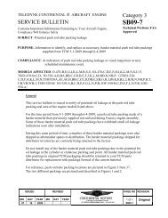
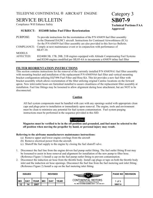
TELEDYNE CONTINENTAL ® AIRCRAFT ENGINESERVICE BULLETINCompliance Will Enhance SafetySUBJECT:IO240B Inline Fuel Filter ReorientationCategory 3<strong>SB07</strong>-9Technical Portions FAAApprovedPURPOSE: To provide instructions for the reorientation of the P/N 656859 fuel filter assemblyin the Diamond DA20C1 aircraft. Instructions for Continued Airworthiness (ICA)for the P/N 656859 fuel filter assembly are also provided in this Service Bulletin.COMPLIANCE: Comply at next maintenance event or in conjunction with performance ofSIL07-10.MODELSAFFECTED: IO240B13B, 17B, 20B, 21B engines equipped with Altitude Compensating Fuel Systemsand IO240 engines modified per SIL05-4A to incorporate a 656859 inline fuel filterFILTER REORIENTATION INSTRUCTIONSThis section contains instructions for the removal of the currently installed P/N 656859A1 fuel filter assemblywith mounting bracket and installation of the replacement P/N 656859A6 fuel filter and vertical mountingbracket configuration utilizing EQ7496 Fuel Filter and Hose Kit. This kit provides a new fuel filter withbracket assembly which allows reorientation of the filter utilizing original Camloc locations on the forwardapron. New inlet/outlet hoses are furnished installed to assure cleanliness of the replacement filter assembly atinstallation. Fuel line fittings may be loosened to allow alignment during hose attachment, but are NOT to bedisconnected.CautionAll fuel system components must be handled with care with any openings sealed with appropriate cleancaps and plugs prior to installation or immediately upon removal. The engine, tools and environmentmust be clean to minimize any potential for fuel system contamination. Fuel system purginginstructions must be performed in the sequence provided in this SID.WARNINGMagnetos must be verified to be in the off position and grounded, and fuel must be selected to theoff position when moving the propeller by hand, or personal injury may result.Referring to the airframe manufacturers maintenance instructions:(a) Remove upper and lower engine cowlings from the aircraft(b) Remove electrical power from the aircraft.(c) Shutoff the fuel supply to the engine by closing the fuel shutoff valve.1. Disconnect the fuel line from the engine driven fuel pump outlet fitting. The fuel outlet fitting B nut maybe loosened to assist in hose removal and alignment for installation of the new pump to filter hose.(Reference Figure 1) Install a cap on the fuel pump outlet fitting to prevent contamination.2. Disconnect the induction air hose from the throttle body. Install cap plugs or tape on both the throttle bodyinlet and the induction air hose openings. Disconnect the fuel line from the fuel metering unit inlet fitting.(Reference Figure 2) Install a cap on the fuel metering inlet fitting.ISSUED REVISED PAGE NO REVISIONMO DAY YEAR MO DAY YEAR CONTINENTAL MOTORS1 of 812 14 2007A <strong>Teledyne</strong> Technologies CompanyP.O. BOX 90 MOBILE ALABAMA 36601 • 251-438-3411<strong>SB07</strong>-9TM
3. Disengage the camlocs that secure the fuel filter mounting bracket to the forward apron assembly. Withfuel lines attached, lift the fuel filter assembly vertically removing the fuel filter assembly with hoses,from the aircraft. (Figure 3)Engine DrivenFuel PumpFuel PumpOutlet ElbowFittingFIGURE 1Throttle andControl UnitMetering UnitInlet FittingFigure 2ISSUED REVISED PAGE NO REVISIONMO DAY YEAR MO DAY YEAR CONTINENTAL MOTORS2 of 812 14 2007A <strong>Teledyne</strong> Technologies CompanyP.O. BOX 90 MOBILE ALABAMA 36601 • 251-438-3411<strong>SB07</strong>-9TM
P/N 659856A1Fuel FilterAssemblyCamlocsFigure 34. Modify the existing opening in the forward baffle assembly as referenced in Figure 4. Alldimensions in mm’s. See Diamond Service Bulletin DAC1-73-05NOTE: A rotary tool with a sanding drum is recommended for the baffle modification.Insure that all fuel and air openings are sealed before starting. Carefully clean allsurfaces after rework to avoid contamination.Figure 4ISSUED REVISED PAGE NO REVISIONMO DAY YEAR MO DAY YEAR CONTINENTAL MOTORS3 of 812 14 2007A <strong>Teledyne</strong> Technologies CompanyP.O. BOX 90 MOBILE ALABAMA 36601 • 251-438-3411<strong>SB07</strong>-9TM
NOTE: All caution must be exercised during maintenance of the fuel system NOTto allow any contaminants to enter the components, lines and fittings duringinstallation. All surfaces surrounding the area where components are to beinstalled must be clean and free of all forms of contaminant before and duringinstallation. Components must be flushed and verified to be free of contaminationprior to final installation.During Installation:(1) Select the proper size open-end wrenches that will fit the fitting body and hose or tubingend fitting.(2) Torque the hose or tubing end fitting to the specified torque using a properly certifiedcalibrated torque wrench while maintaining sufficient force on the component fitting toprevent twisting and shear loads.(3) Support the last fitting in the assembly on components that contain multiple fittingscoupled in one location.(4) DO NOT over torque fittings.5. Confirm hose and fitting clocking of the fuel pump to inline fuel filter hose. This hose must be installedprior to filter installation as it is not accessible when the filter is attached to the forward apron. Whenclocking is verified, torque fitting to 135-190 inch pounds using a calibrated torque wrench. See thefigure below for clocking.P/N 646644S4Y5.00Hose assemblyHose assemblies suppliedwith the 45º fittingsin plane with the fuel filterassembly as shownP/N 656859A6 FuelFilter Assembly. (MountingBracket Omitted for Clarity.)P/N 646644S4Y6.50Hose assemblyFIGURE 56. Leaving the inlet and outlet hose attached to the filter, route the new fuel pump to fuel filter line throughthe forward apron. It will be necessary to guide the fuel line around the back side of the engine driven fuelpump and into the correct position for installation. Assure that that the four lockwired screws are on theISSUED REVISED PAGE NO REVISIONMO DAY YEAR MO DAY YEAR CONTINENTAL MOTORS4 of 812 14 2007A <strong>Teledyne</strong> Technologies CompanyP.O. BOX 90 MOBILE ALABAMA 36601 • 251-438-3411<strong>SB07</strong>-9TM
lower side of the filter installation. Attach the fuel filter to the forward apron by engaging the existingCamloc fasteners on bracket. (Reference Figure 6)7. Restore electrical power to the aircraft. Select the fuel “ON”.8. Remove the fuel pump outlet fitting protective cap. Utilizing the airframe boost pump, flush aminimum of 1 quart of fuel through the fuel pump outlet fitting through a coffee filter into a clean,dry container. If contamination is found, continue to flush until no contaminant is evident. If nocontamination is found, remove protective plug from the fuel pump to filter hose and attach hose tothe fuel pump outlet fitting.9. Torque the fuel pump outlet fitting elbow B nut and the fuel pump outlet hose “B” nut to 135-190Inch-Lbs.10. Remove the plug from the fuel filter to fuel metering unit inlet hose. Utilizing the airframe boostpump, flush a minimum of 1 quart of fuel into a clean, dry container. Inspect the flushed fuel. Ifcontamination is found, locate the source and correct the issue before proceeding further. If nocontamination is present, proceed to the next step.11. Connect the fuel filter outlet line to the metering unit inlet fitting. Torque to 135-190 Inch-Lbs.(Reference Figure 6)P/N 656859A6Fuel FilterAssemblyP/N 646644S4Y5.00Hose AssemblyFIGURE 612. Using the fuel boost pump, leak check the complete engine fuel system. Correct any defects noted beforeproceeding to the next step.13. Perform the fuel system setup and operation verification in accordance with the instructions andspecifications contained in TCM bulletin SID07-3, revision A or later and the instructions contained in thelatest revision of the IO-240 Maintenance Manual TCM Form X30621A. Assure that 639464 caps areinstalled on the fuel metering tee and the manifold tee pressure checking points. Make an engine logbookentry that <strong>SB07</strong>-9 has been complied with.ISSUED REVISED PAGE NO REVISIONMO DAY YEAR MO DAY YEAR CONTINENTAL MOTORS5 of 812 14 2007A <strong>Teledyne</strong> Technologies CompanyP.O. BOX 90 MOBILE ALABAMA 36601 • 251-438-3411<strong>SB07</strong>-9TM
WARNINGOver priming can cause a flooded intake resulting in a hydraulic lock condition and subsequent enginedamage or failure. If the engine is over primed, or flooded, make sure that all fuel has drained from theintake and cylinders prior to attempting engine start.NOTEPressure altitude must be used when determining fuel system set-up values. To determine pressurealtitude prior to take-off, set your altimeter to 29.92 in hg, and the altimeter will indicate your pressurealtitude.14. Using the airframe manufacturers instructions, return the aircraft to its normal configuration.WARRANTYContact <strong>Teledyne</strong> <strong>Continental</strong> <strong>Motors</strong> Customer Service at 1-888-826-5465 for part kit availability and laborclaim filing instructions to allow completion of the modification section of this Service Bulletin.Please provide the following information to TCM representative at time of contact;PARTS REQUIRED1. Model and Serial number of the affected aircraft2. Registration number3. Engine Serial Number4. Total time on engine5. Owner’s Name, Address and Telephone Contact info6. FBO Name, Address and Telephone Contact infoP/N EQ7496 Fuel Filter assembly with hoses1 EAINSTRUCTIONS FOR CONTINUED AIRWORTHINESS<strong>Teledyne</strong> <strong>Continental</strong> <strong>Motors</strong> requires the P/N 656859A6 filter assembly to be inspected after each 200 hoursin service using the following instructions and referencing photo 1.WARNINGMagnetos must be verified to be in the off position and grounded, and fuel must be selected to the offposition when moving the propeller by hand, or personal injury may result.NOTE: All caution must be exercised during maintenance of the fuel system NOT to allow anycontaminants to enter the components, lines and fittings during installation. All surfaces surroundingthe area where components are to be installed must be clean and free of all forms of contaminant beforeand during installation. Components must be flushed and verified to be free of contamination prior tofinal installation.ISSUED REVISED PAGE NO REVISIONMO DAY YEAR MO DAY YEAR CONTINENTAL MOTORS6 of 812 14 2007A <strong>Teledyne</strong> Technologies CompanyP.O. BOX 90 MOBILE ALABAMA 36601 • 251-438-3411<strong>SB07</strong>-9TM
Referring to the airframe manufacturer’s maintenance instructions:(a) Remove electrical power from the aircraft.(b) Remove the upper engine cowling from the aircraft(c) Shutoff the fuel supply to the engine by closing the fuel shutoff valve.1. Disconnect the fuel line from the engine driven fuel pump outlet fitting. The fuel outlet fitting B nut maybe loosened but not removed to assist in hose removal and alignment for installation of the new pump tofilter hose. (Reference Figure 1) Install a cap on the fuel pump outlet fitting to prevent contamination.2. Disconnect the induction air hose from the throttle body. Install cap plugs or tape on both the throttlebody inlet and the induction air hose openings.3. Disconnect the fuel line from the fuel metering unit inlet fitting. (Reference Figure 2) Install a cap on thefuel metering inlet fitting.4. Disengage the camlocs that secure the fuel filter mounting bracket to the forward apron assembly. Withfuel lines attached, lift the fuel filter assembly vertically removing the fuel filter assembly with hoses,from the aircraft. (Figure 3)5. Remove the P/N 656859A6 filter assembly. Cut the safety wire on the four screws holding the P/N 656855cover on the inlet side of the fuel filter assembly. Remove the four screws and remove the cover. Removethe P/N MS9021-020 o-ring from the cover and discard.6. Remove the P/N 656858 filter spring from the filter housing, then remove the P/N 656856 filter disc fromthe housing.7. Clean the filter disc, cover and housing ultrasonically or by soaking in lacquer thinner or acetone forseveral hours. Clean the housing and spring prior to reassembly. Blow the filter disc, housing and springdry with clean, filtered dry compressed air. If any physical damage is noted to the filter disc, it must bereplaced.8. Install the filter disc and then the spring into the filter housing assembly. Install a new P/N MS9021-020 o-ring onto the cover. Lubricate the o-ring with clean engine oil and install the cover onto the filter housingassembly. Secure the cover using the four P/N AN500-A8-7 screws and AN960-8 washers. Torque thecover retaining screws to 17.5 to 22.5 In-Lbs. Lockwire the screws in pairs using 0.032” stainless steellockwire conforming to MS20995 Condition A9. Reinstall the hoses to filter 656859A6 (Reference Figure 5). Route the fuel pump to fuel filter line throughthe forward apron. It will be necessary to guide the fuel line around the back side of the engine driven fuelpump and into the correct position for installation. Assure that that the four lockwired screws are onthe lower side of the filter installation. Attach the fuel filter to the forward apron by engaging theexisting camloc fasteners on bracket. (Reference Figure 6)10. Restore electrical power to the aircraft. Select the fuel “ON”.11. Remove the fuel pump outlet fitting protective cap. Utilizing the airframe boost pump, flush a minimum of1 quart of fuel through the fuel pump outlet fitting through a coffee filter into a clean, dry container. Ifcontamination is found, continue to flush until no contaminant is evident. If no contamination is found,remove protective plug from the fuel pump to filter hose and attach hose to the fuel pump outlet fitting.12. Torque the fuel pump outlet fitting elbow B nut and the fuel pump outlet hose “B” nut to 135-190 inch-lbs.13. Remove the plug from the fuel filter to fuel metering unit inlet hose. Utilizing the airframe boost pump,flush a minimum of 1 quart of fuel into a clean, dry container. Inspect the flushed fuel. If contamination isfound, locate the source and correct the issue before proceeding further. If no contamination is present,proceed to the next step.14. Connect the fuel filter outlet line to the metering unit inlet fitting. Torque to 135-190 Inch-Lbs. (ReferenceFigure5)Using the fuel boost pump, leak check the complete engine fuel system. Correct any defects noted beforeproceeding to the next step.ISSUED REVISED PAGE NO REVISIONMO DAY YEAR MO DAY YEAR CONTINENTAL MOTORS7 of 812 14 2007A <strong>Teledyne</strong> Technologies CompanyP.O. BOX 90 MOBILE ALABAMA 36601 • 251-438-3411<strong>SB07</strong>-9TM
WARNINGOver priming can cause a flooded intake resulting in a hydraulic lock condition and subsequent enginedamage or failure. If the engine is over primed, or flooded, make sure that all fuel has drained from theintake and cylinders prior to attempting engine start.Perform the fuel system verification in accordance with the procedures contained in the latest revision of TCMbulletin SID07-3 and the procedures contained in the latest revision of the IO-240 Maintenance Manual TCMForm X30621A. Assure that all connections are correct and properly torqued.Reinstall the cowlings in accordance with the airframe manufacturer’s maintenance instructions.MS9021-020 O-Ring656855 Cover656854 Housing656856 Filter DiskOr 656851 Cup Filter656858 Filter Spring AN500-8-7 Screw 4 EachAN960-8 Washer 4EachPHOTO 1FUEL FILTER ASSEMBLYISSUED REVISED PAGE NO REVISIONMO DAY YEAR MO DAY YEAR CONTINENTAL MOTORS8 of 812 14 2007A <strong>Teledyne</strong> Technologies CompanyP.O. BOX 90 MOBILE ALABAMA 36601 • 251-438-3411<strong>SB07</strong>-9TM