1B.7âLightning and Other Overvoltage Protection - Pacific Power
1B.7âLightning and Other Overvoltage Protection - Pacific Power
1B.7âLightning and Other Overvoltage Protection - Pacific Power

Create successful ePaper yourself
Turn your PDF publications into a flip-book with our unique Google optimized e-Paper software.
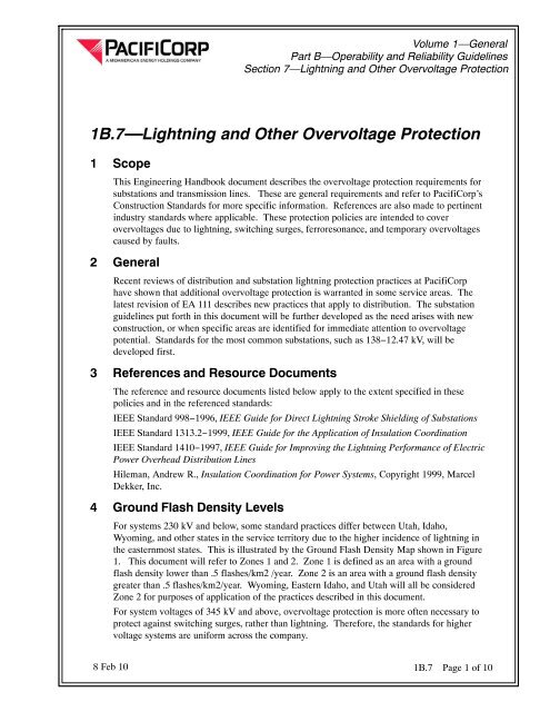
Volume 1—GeneralPart B—Operability <strong>and</strong> Reliability GuidelinesSection 7—Lightning <strong>and</strong> <strong>Other</strong> <strong>Overvoltage</strong> <strong>Protection</strong>Figure 1—U. S. Flash Density Map1B.7 Page 2 of 108 Feb 10
Volume 1—GeneralPart B—Operability <strong>and</strong> Reliability GuidelinesSection 7—Lightning <strong>and</strong> <strong>Other</strong> <strong>Overvoltage</strong> <strong>Protection</strong>Table 1—Transformer Surge Arrester Rating GuideTransformerNameplateVoltageTransformerWinding BILArrester Duty Cycle Rating Stock Item # MCOVGroundedSystemsUngroundedSystemsGroundedSystemsUngroundedSystems525 kV 1425 kV 420 kV n/a (TBD) n/a 335 kV345 kV 1050 kV 264 kV n/a 7882325 n/a 212 kV230 kV 750 kV 180 kV n/a 9600416 n/a 144 kV161 kV 650 kV 132 kV n/a 7887345 n/a 106 kV138 kV 550 kV 120 kV n/a 8100175 n/a 98 kV115 kV 450 kV 96 kV 9600160 76 kV120 kV 7887373 98 kV69 kV 350 kV 60 kV 9602189 48 kV72 kV 1003204 57 kV46 kV 250 kV 39 kV 1004075 31.5 kV48 kV 7887346 39 kV34.5 kV 200 kV 30 kV 7887347 24.4 kV36 kV 7887348 29 kV25.0 kV 150 kV 21 kV 7887095 17 kV27 kV 7887349 22 kV20.8 kV 150 kV 21 kV 7887095 17 kV27 kV 7887349 22 kV13.8 kV 110 kV 12 kV 7887171 10.2 kV15 kV 1008491 12.7 kV13.2 kV 110 kV 12 kV 7887171 10.2 kV15 kV 1008491 12.7 kV13.09 kV 110 kV 12 kV 7887171 10.2 kV15 kV 1008491 12.7 kV12.5 kV 110 kV 12 kV 7887171 10.2 kV15 kV 1008491 12.7 kV5.1.3 Breaker <strong>Protection</strong>—69 kV to 138 kVIn both Zones 1 <strong>and</strong> 2, the high-side breakers shall be protected by lightningarresters installed on the line side of the breakers (Refer to Table 2 for arrestersizes). In some cases, the breaker may be protected by the arrester on thetransformer if they are very close (30 ft. for 138 kV) to one another. Check withSubstation St<strong>and</strong>ards Engineering for any question regarding the need forarresters at the breaker.1B.7 Page 4 of 108 Feb 10
Volume 1—GeneralPart B—Operability <strong>and</strong> Reliability GuidelinesSection 7—Lightning <strong>and</strong> <strong>Other</strong> <strong>Overvoltage</strong> <strong>Protection</strong>Table 2—Line Entrance Surge Arrester Rating GuideNominalSystemVoltageBreaker/Trans. LineBILArrester Duty Cycle RatingGroundedSystemsUngroundedSystemsStock Item NumberGroundedSystemsUngroundedSystemsMCOVArrester MinimumEnergy CapabilityBased on One Shot525 kV 1800/1800 kV 420 kV n/a (TBD) n/a 335 kV 13KJ/KV of MCOV345 KV 1300/1300 KV 276 kV n/a (TBD) n/a 220 kV 9KJ/KV of MCOV230 kV 900/900 kV 180 kV n/a 9600416 n/a 144 kV 5kJ/KV of MCOV161 kV 750/750 kV 132 kV n/a 7887345 n/a 106 kV 5KJ/KV of MCOV138 kV 650/650 kV 120 kV n/a 8100175 n/a 98 kV 5KJ/KV of MCOV115 kV 650/550 kV 96 kV 9600160 76 kV 5KJ/KV of MCOV120 kV 7887373 98 kV 5KJ/KV of MCOV69 kV 350/350 kV 60 kV 9602189 48 kV 5KJ/KV of MCOV72 kV 1003204 57 kV 5KJ/KV of MCOV46 kV 350/250 kV 39 kV 1004075 31.5 kV 5KJ/KV of MCOV48 kV 7887346 39 kV 5KJ/KV of MCOVNotesThe length of 525 <strong>and</strong> 345 kV transmission lines was assumed to be 300 miles or less.The length of 230 <strong>and</strong> 169 kV transmission lines was assumed to be 200 miles or less.The length of 138 to 46 kV transmission lines was assumed to be 150 miles or less.5.1.4 High-Side Bus <strong>Protection</strong>If there are no high−side breakers, spill gaps shall be installed at the transmissionline terminals in both Zones 1 <strong>and</strong> 2. Table 3 lists the requirements for spill gaps.Maximum System VoltagePhase-to-phase(kV)Table 3—Spill Gap SettingsBasic Impulse Insulation Level(BIL)(kV)Spill gap spacing S at sea level(inches)48 250 7.572.5 350 11121 550 19145 650 23169 750 27242 900 408 Feb 10 1B.7 Page 5 of 10
Volume 1—GeneralPart B—Operability <strong>and</strong> Reliability GuidelinesSection 7—Lightning <strong>and</strong> <strong>Other</strong> <strong>Overvoltage</strong> <strong>Protection</strong>Table 4—Altitude Correction FactorsAltitude (ft) 500 1000 1500 2000 2500 3000 3500Correction Factor δ (Note 3) 0.982 0.965 0.948 0.931 0.915 0.899 0.883Altitude (ft) 4000 4500 5000 5500 6000 6500 7000Correction Factor δ (Note 3) 0.868 0.852 0.837 0.823 0.808 0.794 0.780Note 1. The spill gaps are set to withst<strong>and</strong> a 2.5 pu switching surge at sea level, using the formula:(IEEE Std.1313.2−1999 Eq. 27), where k g = the gap factor given in Table 10.For rod−to−rod (vertical) gaps, the value = 1.30, <strong>and</strong> CFO is the switching surge.Note 2. Switching surge line-to-ground at sea level is calculated using the formula:where E max = the system’s maximum voltage <strong>and</strong> pu = the per unit switching surge factor.Note 3. To find spill gap setting at different altitude, use the values listed in Table 4, which weredeveloped with the formula:where A = the altitude in kilometers. The setting at sea level should be divided by thealtitude correction factor to get the gap setting at the desired altitude.Note 4. The settings were checked to be below the withst<strong>and</strong> capabilities of the station postinsulator,determined with the formula:This formula is from IEEE 1313.2−1999, Eq. 23, where H i is the insulator height inmeters, <strong>and</strong> BSL is the basic switching level.5.1.5 Feeder Getaway <strong>Protection</strong>Underground Getaways − Riser pole arresters shall be installed on both ends ofunderground getaways in open−bus substations. For underground getaways1B.7 Page 6 of 108 Feb 10
Volume 1—GeneralPart B—Operability <strong>and</strong> Reliability GuidelinesSection 7—Lightning <strong>and</strong> <strong>Other</strong> <strong>Overvoltage</strong> <strong>Protection</strong>exiting from metalclad switchgear, an arrester shall only be installed at the riserpole on the load side of the getaway.Overhead Getaways − Distribution class arresters shall be installed as close aspossible to the getaway conductors where they attach to the substation busstructure.5.2 Substations with Voltages of 161 kV <strong>and</strong> Above5.2.1 Substation ShieldingAll transmission substations shall be shielded. The fixed angle method, per IEEE998, shall be used with a 45-degree angle for heights up to 60 feet, <strong>and</strong> 30-degreeangle for heights above 60 feet.5.2.2 Transformer <strong>Protection</strong>All power transformers shall be protected with high− <strong>and</strong> low−side lightningarresters. Refer to Table 1, <strong>and</strong> PacifiCorp Material Specification ZS 001 forarrester sizes.5.2.3 Breaker <strong>Protection</strong>All breakers, at voltages of 69 kV <strong>and</strong> above, shall be protected by line entrancearresters. The example in Figure 3 illustrates that 138 <strong>and</strong> 230 kV line terminalswith breakers, previously protected by spill gaps, will now have arrestersinstalled. Refer to Table 2 for arrester sizes.5.2.4 High−Side Bus <strong>Protection</strong>If there are no high−side breakers, spill gaps shall be installed at the transmissionline terminals. Table 3 lists the requirements for spill gaps.8 Feb 10 1B.7 Page 7 of 10
Volume 1—GeneralPart B—Operability <strong>and</strong> Reliability GuidelinesSection 7—Lightning <strong>and</strong> <strong>Other</strong> <strong>Overvoltage</strong> <strong>Protection</strong>Figure 3—Typical Transmission Substation <strong>Overvoltage</strong> <strong>Protection</strong>6 Transmission Line <strong>Overvoltage</strong> <strong>Protection</strong>6.1 Shield WireRefer to PacifiCorp Transmission Construction St<strong>and</strong>ard TD 201, ShieldWire—Lightning <strong>Protection</strong> Locations1B.7 Page 8 of 108 Feb 10
Volume 1—GeneralPart B—Operability <strong>and</strong> Reliability GuidelinesSection 7—Lightning <strong>and</strong> <strong>Other</strong> <strong>Overvoltage</strong> <strong>Protection</strong>7 Issuing Department, Approvals <strong>and</strong> AuthorizationThe Asset Management Department of PacifiCorp is responsible for issuing this document.Comments <strong>and</strong> suggestions are welcome. Additional copies may be obtained from:Asset Management Documentation, Lloyd Center Tower825 NE Multnomah St., Suite 1600, Portl<strong>and</strong>, Oregon 97232Telephone: (503) 813−5293 Fax: (503) 813−6804Signed approval records are on file. Publication <strong>and</strong> use of this document in support ofPacifiCorp projects is authorized by the employees listed below.Approved:Iuda Morar, EngineerSt<strong>and</strong>ards Engineering <strong>and</strong> Technology DevelopmentApproved:Greg Lyons, ManagerSt<strong>and</strong>ards Engineering <strong>and</strong> Technology Development8 Feb 10 1B.7 Page 9 of 10
Volume 1—GeneralPart B—Operability <strong>and</strong> Reliability GuidelinesSection 7—Lightning <strong>and</strong> <strong>Other</strong> <strong>Overvoltage</strong> <strong>Protection</strong>This page is left blank intentionally.1B.7 Page 10 of 108 Feb 10