lever operated directional control valve dls10 - Polyhydron Group of ...
lever operated directional control valve dls10 - Polyhydron Group of ...
lever operated directional control valve dls10 - Polyhydron Group of ...

You also want an ePaper? Increase the reach of your titles
YUMPU automatically turns print PDFs into web optimized ePapers that Google loves.
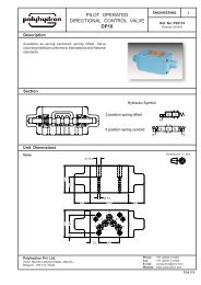
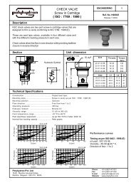
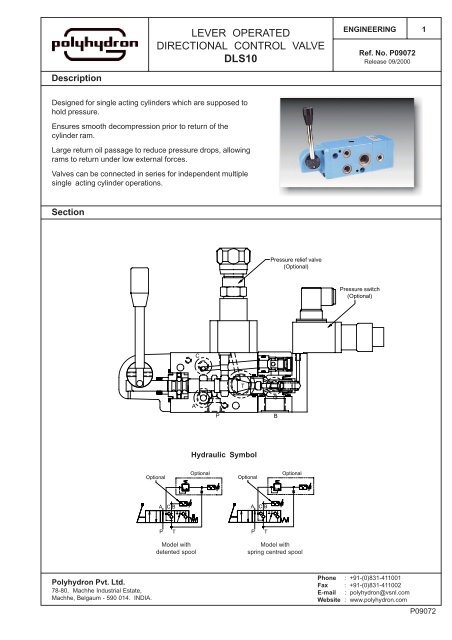
LEVER OPERATEDDIRECTIONAL CONTROL VALVEDLS10ENGINEERINGRef. No. P09072Release 09/20001DescriptionDesigned for single acting cylinders which are supposed tohold pressure.Ensures smooth decompression prior to return <strong>of</strong> thecylinder ram.Large return oil passage to reduce pressure drops, allowingrams to return under low external forces.Valves can be connected in series for independent multiplesingle acting cylinder operations.SectionPressure relief <strong>valve</strong>(Optional)Pressure switch(Optional)CTAPGBHydraulic SymbolOptionalOptionalOptionalOptionalAC BACBP T P TModel withdetented spoolModel withspring centred spool<strong>Polyhydron</strong> Pvt. Ltd.78-80, Machhe Industrial Estate,Machhe, Belgaum - 590 014. INDIA.Phone : +91-(0)831-411001Fax : +91-(0)831-411002E-mail : polyhydron@vsnl.comWebsite : www.polyhydron.comP09072
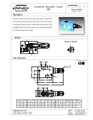
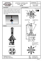
LEVER OPERATEDDIRECTIONAL CONTROL VALVEDLS10ENGINEERINGRef. No. P090722Unit dimensionDimensions in mm.B (G3/4)62.5*20P (G3/8)35705879.592 ~92 ~Optional36°36°M8x14 deep,2 nos. for mounting.(alternate)Optional216 ~190 ~79.568.5615950373519940.61323.543.3C (G1/4)T (G3/4)7348.3A(G3/8)P49.744.5G (G1/4)68 180101BHole for M8x70L,S.H.C. screws, 2 nos.for mounting.Note :Valve with 'Mirror Image' face option will have ports A, C, T and G on opposite face anddimension 20 (marked *) <strong>of</strong> port P will be 50.P09072
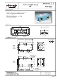
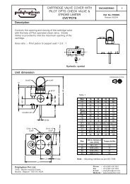
LEVER OPERATEDDIRECTIONAL CONTROL VALVEDLS10ENGINEERINGRef. No. P090723Technical specificationConstruction .......................................... Spool and poppet type.Mounting type ........................................ Threaded body.Mounting position .................................. Optional, horizontal spool axis preferred.Flow passage areas .............................. Refer hydraulic symbol.Operating Pressure ............................... For ports P, A, B, C, G ......... 350 barT ......... 7 bar max.Hydraulic medium ................................. Mineral oil.Viscosity range ...................................... 10 to 380 cSt.Working temperature range .................. -20 °C to +70 °C.Fluid cleanliness requirement ............... As per ISO code 16/13 or better.Nominal flow handling capacity ............. Refer flow V/s. pressure drop graph.Mass ...................................................... 7.8 kg.Performance CurvesOil Used : ISO VG 68, Viscosity : 68 cSt @ 40 °C, Temp @ test : 50 °C.Pressure drop bar13119753Flow P to AFlow P to BFlow B to T100 10 20 30 40 50 60 70 80 90Flow l/min.Hydraulic circuit showing typical application <strong>of</strong> <strong>valve</strong>s 4DLS10 **P09072
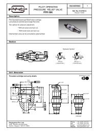
LEVER OPERATEDDIRECTIONAL CONTROL VALVEDLS10ENGINEERINGRef. No. P090724Ordering code4 DLS 10 D M BA 315 013 Service ports4 Service portsDirectional <strong>control</strong><strong>valve</strong> <strong>lever</strong> optd.with pr. holdingfacility at it's port B.Size 10Design code subject tochange. Installationdimensions remain samefor design code 01 thru 09.Optional forpressure regulator200, 315, 400 bar.Omit if not requiredSpool holding optionsSpring centred SDetented DFace option for portsA, C, T, and G only.For <strong>valve</strong> porting shown inunit dimension drawing.Ports on opposite face(mirror image).OmitMOptional for pressure switch( 350 bar max.on port B )Optional for pressure switch( 4 bar min. on port T <strong>of</strong> pr.regulator)BA Standard connector TA Standard connectorBB 230 VAC With LED TB 230 VAC With LEDBC 24 VDC connector TC 24 VDC connectorOmit if not requiredAll rights reserved.Subject to revision.P09072