Architectural Level Power Optimization Techniques for Multipliers
Architectural Level Power Optimization Techniques for Multipliers
Architectural Level Power Optimization Techniques for Multipliers

You also want an ePaper? Increase the reach of your titles
YUMPU automatically turns print PDFs into web optimized ePapers that Google loves.
International Journal of Engineering Trends and Technology- Volume3Issue5- 2012<strong>Architectural</strong> <strong>Level</strong> <strong>Power</strong> <strong>Optimization</strong><strong>Techniques</strong> <strong>for</strong> <strong>Multipliers</strong>V.Alekhya #1 , B.Srinivas *2Department of ECE, MVGR College Of EngineeringVizianagaram, AP, IndiaAbstract— In this work, a new topology was proposed tooptimize the power dissipation of <strong>Multipliers</strong>. Low powerdigital Multiplier Design based on bypassing techniquemainly used to reduce the switching power dissipation.While this technique offers great dynamic power savingsmainly in array multipliers, due to their regularinterconnection scheme, it misses the reduced area andhigh speed advantages of tree multipliers. There<strong>for</strong>e,mixed style architecture, using a traditional tree basedpart, combined with a bypass, array based part, isproposed. Prototyping of all these multiplierArchitectures has been carried out on Spartan3E FPGA.By Evaluating the per<strong>for</strong>mance of these Multiplierarchitectures using Xilinx ISE tool suite , it has beenfound that while the bypass technique offers theminimum dynamic power consumption, the mixedarchitecture offers a delay*power product improvement ,compared to all other architectures.I. INTRODUCTIONLow power issues have become an important factor inmodern VLSI design. The limited power capacitysystems had given rise to more power aware designs bydesigners. Now-a-days, power has become a crucialfactor than area or speed. However, differentimplementation technologies present different poweroptimization opportunities. In technologies above 0.1m, dynamic power is the dominant contribution to thetotal power dissipated while in smaller technologies;leakage power is gaining more importance.Dynamic power dissipation is the result of charging theload capacitances in a circuit. It is given by equationwhere is theoutput capacitance, the supply voltage, E(sw)(called switching activity) is the average number oftransitions and the clock frequency.Leakage power dissipation is divided in two majorparts, the sub-threshold leakage and the gate-oxideleakage. The sub-threshold leakage is caused by shortchannel effects and low threshold voltage (Vth), whilethe gate-oxide leakage is exponentially increasing withdecreasing oxide thickness.In the past, different architectural optimizations havebeen applied in order to minimize dynamic powerdissipation in arithmetic circuits, and especially indigital multipliers. <strong>Multipliers</strong> are very importantdevices in DSP applications, like <strong>for</strong> example FIRfilters, leading to excessive power consumption.Consequently, the design of low power multipliers is anecessity <strong>for</strong> the design and implementation of efficientpower-aware devices.There are two main choices <strong>for</strong> the design of amultiplier. The first is the Wallace tree <strong>for</strong>m, which hasthe advantage of a logarithmic circuit delay, and thesecond is the array multiplier <strong>for</strong>m, like the Carry-Savearray, where the delay is linear. On the other hand thearray multiplier has a regular structure, which leads to adense layout making it ideal <strong>for</strong> fabrication.The Wallace tree has irregular structure, occupies morearea on the wafer, and needs greater wiring <strong>for</strong> cellinterconnections. This point is crucial <strong>for</strong> present andemerging IC technologies, where interconnection playsa predominant role. This factor makes the Wallace treeinappropriate <strong>for</strong> low power applications.In this paper, we present a technique to minimizepower dissipation in digital multipliers, starting fromdynamic power and concentrating on the switchingactivity. There have been proposed a lot of techniquesto reduce the switching activity of a logic circuit. In thesequential world one of the most successful is clockgating, where an enable signal inhibits the clock,isolating a large block of the circuit. This techniqueeliminates activity and thus, power consumption. Forexample, in, clock gating is applied in pipelined arraymultipliers with significant power gains. In purecombinational circuits the main ef<strong>for</strong>t of research hasbeen to rearrange the tree of gates in a more profitablescheme, or to insert clock gated registers which providethe desired isolation.The contribution of this paper is the evaluation of atechnique similar to clock gating. To isolate parts of acircuit, transmission gates are used as low delay andarea overhead bypass switches. An array multiplierwith bypass transmission gates can offer powerreductions of more than 50%. Similar bypass ideasISSN: 2231-5381 http://www.internationaljournalssrg.org Page 574
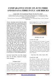
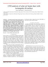
International Journal of Engineering Trends and Technology- Volume3Issue5- 2012with different isolating components have also beenreported in the past, in. However, our contributionmoves one step further and proposes a mixedarchitecture, to address both dynamic power dissipationand per<strong>for</strong>mance, by doing half of the multiplicationthrough an array structure, with bypass transmissiongates, and the other half through a Wallace tree. Thismixed architecture offers a delay*power productimprovement ranging from 1.2x to 6.5x, compared toall other architectures.Minimization of the switching activity in a digitalcircuit can be per<strong>for</strong>med by isolating and blockingunits producing non-valuable partial results, in order tosave power. To per<strong>for</strong>m isolation, transmission gatescan be used, as ideal switches with small powerconsumption, propagation delay similar to the inverter,and small area. Isolation by transmission gates can beapplied to any kind of logic circuit. However in thispaper we are considering digital multipliers, startingwith the canonical and widely used Carry-Save arraytopology.Figure2(a). FA* cellII. Basic ArchitecturesA. Carry Save Array MultiplierThe Carry-Save array multiplier is a straight<strong>for</strong>wardimplementation of vector multiplication. It is preferredin some implementations because of its canonicalinterconnect topology. It consists of a partial productreduction tree, which is used to calculate partialproducts in Carry-Save redundant <strong>for</strong>m, and a finalchain adder to trans<strong>for</strong>m the redundant <strong>for</strong>m in normalbinary <strong>for</strong>m. A 4x4 Carry-Save multiplier is shown infigure 1.Figure2(b). FAB CellEach FA* cell per<strong>for</strong>ms the multiplicationusing an AND gate and then adds the result with theincoming carry bits, to produce an output sum and anoutput carry. All FA* cells are appropriately connected(sums and carries) as shown in figure 1, to per<strong>for</strong>m themultiplication. The final adder shown in figure 1 isused to merge the sums and carries from the last row ofthe array, since in every row the carry bits are notimmediately added but rather propagated to the rowbelow.We can see that whenis 0 then the correspondingdiagonal cells are functioning unnecessarily. In allthese cells the partial products and the carryinputs are zero <strong>for</strong>and thischain does not contribute to the <strong>for</strong>mation of theproduct. Consequently, the sum output of the abovecell can bypass this unimportant diagonal with the useof transmission gates. To achieve all of the above wecan replace the FA* cell with the cell in figure 2(b)(called the FAB cell).Figure1. A 4x4 Carry-Save multiplierThe functionality of the Carry-Save array multiplier isas follows: We assume thatandare unsigned numbers.The bits are fed into an array of FA* cells (figure 2(a)).B. CSA with Bypassing TechniqueThe transmission gates in the FAB cell lock the inputsof the full adder to prevent any transitions. When, and a multiplexer propagates the sum input tothe sum output. When , the sum output of thefull adder is passed. The carry input does not generateany new value since the initial diagonal carry input isISSN: 2231-5381 http://www.internationaljournalssrg.org Page 575
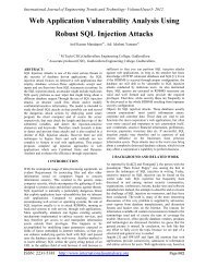
International Journal of Engineering Trends and Technology- Volume3Issue5- 2012always 0. So, no transmission gate is used to block it. If, to fix any erroneous carry generated fromprevious computations, an AND gate is used be<strong>for</strong>e thefinal adder to make the final diagonal carry output 0.The whole structure of the modified multiplier ispresented in figure 3.The benefit of the Wallace tree is that there are onlyreduction layers, and each layer haspropagation delay. As making the partial products isand the final addition is, themultiplication is only, not much slowerthan addition (however, much more expensive in thegate count). Naively adding partial products withregular adders would requiretime.D. Mixed ArchitecturesThe mixed architecture is nothing but the combinationof Wallace tree and Array structure. The great timingadvantage of the Wallace tree along with the greatpower advantage of the bypass scheme can becombined in a mixed architecture. The figure <strong>for</strong> mixedarchitecture is shown in figure 5.Figure3. 4 x 4 Carry Save Array Multiplier withBypassC. Wallace Tree MultiplierWallace tree is an efficient hardware implementation ofa digital circuit that multiplies two integers.In general, array multipliers offers dynamic powersaving but it fails to give a reduced area and fast speedadvantages because of their regular interconnectionpattern. So, tree multipliers are introduced to achievereduced area and fast speed, to achieve both delay andpower advantages it is better to use a differentarchitecture that is having two parts one is tree basedpart and other is bypass architecture. The modifiedbypass technique offers minimum dynamic powercompared to normal carry save array multiplier. Thetree based part of the mixed architecture has enoughtiming slack to be implemented using high thresholdvoltage components.Two 8 bit values can be multiplied by splitting eachone of them in two 4 bit parts.Figure4. Wallace TreeThe Wallace tree has three steps:1. Multiply (that is - AND) each bit of one of thearguments, by each bit of the other, yieldingresults.2. Reduce the number of partial products to twoby layers of full and half adders.3. Group the wires in two numbers, and addthem with a conventional adder.ISSN: 2231-5381 http://www.internationaljournalssrg.org Page 576
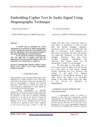
International Journal of Engineering Trends and Technology- Volume3Issue5- 2012all other multipliers in various aspects. Mainly from theper<strong>for</strong>mance point of view, it was observed theyprovide low switching power dissipation with a slightincrease in the delay.The following table (Table I) shows variousper<strong>for</strong>mance metrics of all the <strong>Multipliers</strong>.Figure5. A 16 bit multiplication split in partsIf the first 8 bit value is (A,B) and the second is (C,D),four 8 bit products are generated, ,, and . Thesefour partial products shifted and added togethergenerate the final 16 bit multiplication.The key point behind operand splitting is to usedifferent multiplier architectures <strong>for</strong> each partialmultiplication. In the example of figure 5,andare per<strong>for</strong>med inWallace multipliers while the others in a bypassarchitecture. So, fromandper<strong>for</strong>mance is gained while fromandpower is gained. If half of one or bothoperands usually contain more 0s than 1s, this specifichalf should be passed through the bypass multiplier <strong>for</strong>greater power improvements. For example, thearchitecture of figure 5 gives better results whencontains on average more 0s than 1s.III. Per<strong>for</strong>mance EvaluationThe Per<strong>for</strong>mance Evaluation of Bypass <strong>Multipliers</strong>Was per<strong>for</strong>med <strong>for</strong> the resolution of 4x4 using Xilinxtool suite. When compared to other architectures, suchas Wallace and normal multipliers, it is power efficient.The test cases that were used <strong>for</strong> this purpose aregenerated in a random fashion. By combining 4x4Wallace tree and bypass multipliers, mixed stylemultiplier was implemented with a resolution of 8x8.The Per<strong>for</strong>mance of this topology was compared withMultiplierTopologyCarry saveArrayMultiplierCarry saveArrayMultiplierCarry saveArrayMultiplierCarry saveArrayBitsSwitching<strong>Power</strong>Dissipation(mW)Critical PathDelay(ns)Area(interms ofLUTs)<strong>Power</strong>DelayProduct(picoJoules)4x4 2.89 14.15 26 40.898x8 4.11 22.34 124 91.8116x16 5.06 45.9 494 232.2532x32 6.7 87.6 2014 586.92MultiplierBypass 4x4 2.65 12.131 27 32.14Bypass 8x8 3.02 22 117 66.44Bypass 16x16 4 42.82 493 171.28Bypass 32x32 4.88 83.98 2013 409.82Wallace 4x4 2.67 12.782 31 34.12Wallace 8x8 3.13 24.68 132 77.24Wallace 16X16 6.34 46 532 291.64Wallace 32X32 8.14 88.6 2100 721.2MixedStyleMultiplierMixedStyleMultiplierMixedStyleMultiplierMixedStyleMultiplier8x8 3.31 19.8 135 65.5316x16 3.57 31.8 549 113.5232X32 5.22 53.42 2170 278.8564X64 6.58 96.92 8457 637.73Table I: Per<strong>for</strong>mance MetricsFunctional Simulations of all the multipliers is carriedout using Xilinx Simulator, Isim.IV. ConclusionIn this work, we have implemented <strong>Multipliers</strong> <strong>for</strong> Lowpower Applications. For power optimization, two basicalgorithms, namely Wallace Tree and Array Multiplier,are combined to exploit the low power and HighISSN: 2231-5381 http://www.internationaljournalssrg.org Page 577
International Journal of Engineering Trends and Technology- Volume3Issue5- 2012Per<strong>for</strong>mance gains from the individual architectures.This topology, called as mixed style Multiplier wasimplemented on Spartan 3E FPGA and it was observedthat the power dissipation and the critical path delayare fairly lower than the normal multiplier. <strong>Power</strong>Measurements were per<strong>for</strong>med using Xilinx “X-<strong>Power</strong>Analyzer “, <strong>for</strong> a test case like random patterns. It ispossible to extend the resolution of the mixed stylemultiplier, without affecting the per<strong>for</strong>mance. Also,this design can be implemented by using standard celllibraries designed <strong>for</strong> low power, with ASICDevelopment Kit, <strong>for</strong> improving the per<strong>for</strong>mancerelatively.V. References1) Dimitris Bekiaris, George Economakos andKiamal Pekmestzi, "A Mixed Style MultiplierArchitecture <strong>for</strong> Low Dynamic and Leakage<strong>Power</strong> Dissipation," in International Symposiumon VLSI Design Automation and Test (VLSI-DAT). IEEE, 2010, pp. 258-2612) M. Karlsson, “A generalized carry-save adderarray <strong>for</strong> digital signal processing,” in 4th NordicSignal Processing Symposium. IEEE, 2000, pp.287–290.3) P. Meier, R. A. Rutenbar, and L. R. Carley,“Exploring multiplier architecture and layout <strong>for</strong>low power,” in Custom Integrated CircuitsConference. IEEE, 1996, pp. 513–516.4) N. Weste and D. Harris, CMOS VLSI Design: ACircuits and Systems Perspective - Third Edition.Addison-Wesley, 2004.5) C. C. Wang and G. N. Sung, “Low-powermultiplier design using a bypassing technique,”Journal of Signal Processing Systems, 2008.6) S. Kim, S. Hong, M. Papaefthymiou, and W. E.Stark, “Low power parallel multiplier design <strong>for</strong>dsp applications through coefficient optimization,”in 12th Annual International ASIC/SOCConference. IEEE, 1999, pp. 286–290.7) G. Economakos and K. Anagnostopoulos, “Bitlevel architectural exploration technique <strong>for</strong> thedesign of low power multipliers,” in InternationalSymposium on Circuits and Systems. IEEE, 2006.ISSN: 2231-5381 http://www.internationaljournalssrg.org Page 578