Advanced Packaging - DfR Solutions
Advanced Packaging - DfR Solutions
Advanced Packaging - DfR Solutions

You also want an ePaper? Increase the reach of your titles
YUMPU automatically turns print PDFs into web optimized ePapers that Google loves.
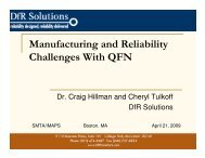
<strong>Advanced</strong> <strong>Packaging</strong><strong>DfR</strong> <strong>Solutions</strong> Open HouseDecember 14, 2011Presented by: Greg Caswell© 2004 -– 20072010
Agendao Package on Package -3D(PoP)o System in Package 3D (SiP)o Through Silicon Via (TSV)o Bottom Terminated Componentso QFNo LFCSPo .3 mm pitch CSPo Copper Wire Bonding© 2004 - 2007 2010
© 2004 - 2007 2010Roadmap vs Market Application
Benefits of PoPo The benefits of PoP are well known. They includeo Less board real estateo Better performance (shorter communication pathsbetween the micro and memory)o Lower junction temperatures (at least compared tostacked die)o Greater control over the supply chain (opportunity toupgrade memory and multiple vendors)o Easier to debug and perform F/A (again, compared tostacked die or multi-chip module or system in package)o Ownership is clearly defined: Bottom package is thelogic manufacturer, the top package is the memorymanufacturer, and the two connections (at least for onepass)are the OEM© 2004 - 2007 2010
Benefits of PoPo The benefits of PoP are well known. They includeo Less board real estateo Better performance (shorter communication pathsbetween the micro and memory)o Lower junction temperatures (at least compared tostacked die)o Greater control over the supply chain (opportunity toupgrade memory and multiple vendors)o Easier to debug and perform F/A (again, compared tostacked die or multi-chip module or system in package)o Ownership is clearly defined: Bottom package is thelogic manufacturer, the top package is the memorymanufacturer, and the two connections (at least for onepass)are the OEM© 2004 - 2007 2010
Smartphone advancements aided by PoP technologyand cost of ownership benefits.PoP addresses integration challenges to enablesemiconductor advancements . . .. . . to cost affectively deliver physicalworld benefits.© 2004 - 2007 2010
Stacked Packages = PoP – 3D 101Double stackPoPTriple stackCourtesy: ASE© 2004 - 2007 2010Double stack
Thermal Comparison© 2004 - 2007 20108
PoP Assembly Processo Assembly of PoP can be throughone or two reflowso Most commonly singlereflow (aka, one-pass)o Top package is typicallydipped before placemento Flux (sticky) or solder paste© 2004 - 2007 20109
1 st Generation PoP – Infrastructure DevelopmentOEMsArchitecturestackingIndustryStandardsEquipmentEMS / ODMLogic IDMMemory IDM12 major OEMs in Handset and DSC market adopting PoPJEDEC – JC.11.2 Design guide, JC11.11 POD, JC-63 pin outsPanasonic, Siemens, Fuji, Unovis, Assembléon, Hitachi5 major EMS providers in production or development15 major IDMs adopted PoP8 major Memory suppliers adopted PoPAmkorFull service – Develop, Design, Model, Standards, bottom,top PoP, Modules, pre-stacked engineering samples, BLRPractical Components – stocks Amkor 12, 14 & 15mm bottom / top DC sampleswww.amkor.com Design, stacking, test and Brd level reliability (joint study papers)© 2004 - 2007 2010
Design Factors Impacting Warpage• Die– Die size– Die Thicknesso Moldo Material propertyo Shrinkageo Thickness• Die attach– Material property– Thickness• Laminate Substrate– Properties– Thickness– Cu ratio– Routing© 2004 - 2007 2010
Package Warpageo Due to mismatch in CTE betweenthe substrate, mold compoundand dieo Die attach can also play a roleo High Tg mold compounds areused to balance CTE mismatchbetween die and substrateo Effect of mold compoundbecomes negligible at reflowtemperatures© 2004 - 2007 201012
Warpage and Yields© 2004 - 2007 201013
Warpage and Reflow ProfileRamkumar, 2008 European Electronic Assembly Reliability Summit© 2004 - 2007 201014
1 st Gen PoP Technologies limit PoP I/O and Bottom StackedDie Density – Requiring New Technologyo Die stacking in bottom package requires thicker mold capo New memory architectures require higher I/O interfaceso Higher Semiconductor density requires package size reductiono Thin form factors and increased battery size require thinner PoP stackso Improved warpage control required when go thinner with higher densityo A new bottom PoP technology is needed to continue growth0.50mm pitchMultiple die in bottom package© 2004 - 2007 2010
Thru Mold Via Technology (TMV®)o Enabling technology for next generation PoP reqmtso Improves warpage control and PoP thickness reductiono TMV removes bottlenecks for fine pitch memory interfaceso Increases die to package size ratio (30%)o Improves fine pitch board level reliabilityo Supports Wirebond, FC, stacked die and passiveintegration© 2004 - 2007 2010
Construction and package stack-up for the TMV PoPTest VehicleReference : "Surface Mount Assembly and Board Level Reliability for HighDensity PoP (Package on Package) Utilizing Through Mold ViaInterconnect Technology - Joint Amkor and Sony Ericsson", Paper© 2004 - 2007 2010
Categories of SiP – examples of 3DHorizontal PlacementWire Bonding TypeFlip Chip TypeStackedStructureInterposer TypeInterposer-lessTypeWire BondingTypeWire Bonding +Flip Chip TypeTerminal Through Via TypeFlip Chip TypeEmbedded StructureChip(WLP) Embedded+ Chip on Surface Type3D Chip EmbeddedTypeWLP Embedded + Chip on Surface Type© 2004 - 2007 2010
SiP: from Die to Package to Hybrid StackingThe Road to 3D <strong>Packaging</strong>3D IC PoPaWLP PoP8 diesExposed-die aMAPPoPBare-die FC PoP4 diesaMAP PoP(Cu pillar)aEDSi PoPdie stackingPIP FCCSPaMAP PoPASICEDS PoPTRD PoPHybrid FCCSPCoC FBGA2.5D IC SiPCourtesy: ASE© 2004 - 2007 2010~2010 2011 20122013
TSV DevelopmentCourtesy:ASE© 2004 - 2007 2010
Silicon InterposerChip 1 Chip 2Si InterposerSubstrateSi Interposer w/ TSV65 nm ASICCourtesy ASE© 2004 - 2007 2010
Samsung TSV ImplementationXBit: Aug 17, 2011:Samsung announcementof 32 Gbit Memory withTSV© 2004 - 2007 2010
Through-Silicon-Viaso Through Silicon Vias (TSV) are the next generationtechnology for system in package deviceso Similar to plated through holes in a PCBo Promised advantages includeo Thinner packageso Greater level of integration between active die.o Process still being optimized and cost must be reducedfor widespread adoption.© 2004 - 2007 2010
TSV (cont.)TSV is rarely justified by just miniaturization aloneMore cost-effective to thin, stack and wire bondCost can be 2X-4X price of flip chip ($200/wafer is the goal)and 5X-10X the price of wire bondingTSV will be justified byperformanceIncrease in inter-die I/OIncrease in bandwidthDecrease ininterconnect lengthhttp://www.intel.com/technology/itj/2007/v11i3/3-bandwidth/6-architectures.htm (August 22, 2007)© 2004 - 2007 201024
TSV Processeso Via First, before Front End of Line (FEOL)o Vias etched in bare wafer prior to fabo Not likelyo Back End of Line (BEOL)o Via First, before BEOLo Via Last, after BEOLo Vias can be created at various stages of the processo By the wafer provider, IC manufacturer, or packaging house© 2004 - 2007 2010
© 2004 - 2007 2010TSV Process – BEOL
How Can Through Silicon Vias (TSV) Fail?o Three primary failure mechanismso Cracking of the Copper Platingo Cracking of the Silicon /Change in Resistance of Silicono Interfacial Delamination of Via Wall from Silicono Challengeso The exact process and architecture (materials, design) for TSVhas yet to be finalizedo Can lead to large changes in stress state© 2004 - 2007 2010
TSV Designo Via walls can be straight (etch) or tapered (laser)o Vias can be filled (likely) or not filled (aka, annular)© 2004 - 2007 2010
TSV Designo Depending on Via First or Via Last design layout, TSVcan have a ‘floor’ of coppero Also known as Carpeted or NailheadingS. Barnat et. al., EuroSIME 2010© 2004 - 2007 2010
TSV Materialso Will the via be filled?o If yes, with what material?o Coppero Tungsteno ConductivepolymerWhy Tungsten?Low CTE mismatch withSilicon© 2004 - 2007 2010
Via Fill (Tradeoffs)o Solid Fill (copper, nickel, tungsten, aluminum, etc.)o Most robust (fatigue)o High stress in silicono Longest processo Enhanced thermal performanceo Greater density (think filled microvias)o Polymer Fillo Still robusto Reduced stress in silicono Shorter process, more expensive materialo No Fill (annular)o Least robusto Lowest stress in silicono Fastest process, lowest cost© 2004 - 2007 2010
Cracking of Copper TSVo Will copper in TSV experience fatigue cracking?o Classic circumferential fatigue cracking of copper plating iscurrently unlikely for two reasonso Reason #1: Hole Fillo Most TSV concepts seem to be moving to a solid plug design(fully filled)o A partial fill or plated barrellikely a process defect(pinch off due to non-optimizedleveler)© 2004 - 2007 2010
Example: Filled PCB Viaso Filled PCB vias (copper, solder,or conductive fill) do not failwhen subjected to temperaturecyclingo KEY EXCEPTIONo Partially filled PCB vias fail fasterdue to the presence of a stressconcentration© 2004 - 2007 2010
Cracking of Copper TSV (cont.)o Reason #2: Unfilled Via and Compressive Stresso Unlike in PCB, the ‘matrix’ (i.e., silicon) has a lower coefficient ofthermal expansion (CTE) than the barrelo There is also a lower CTE mismatcho PCB: 50ppm vs. 17ppm (33) / TSV: 2ppm vs. 17ppm (-15)o If electroplated, stress free state should be at roomtemperatureo Any increase in temperature, due to hot spots or change in ambientconditions, will place the copperplating under an axial compressive stresso The tensile stress then arises circumferentiallyo Could induce cracking along the length ofthe via, but will not cause electrical failure© 2004 - 2007 2010
Cracking of Copper TSV – Possible Exceptionso Lu claimed very large stresses in the copper plating forannular TSVLu, Dissertation, UTexas, 2010© 2004 - 2007 2010
Cracking of Copper TSV – Possible Exceptionso Liu measured (XRD) similar stress levels in filled TSVNote zero stress stateLiu, ECTC, 2009© 2004 - 2007 2010
Cracking of Copper TSV – Possible Exceptions (cont.)o One publication seems to show stress-driven crackingof TSV, but little additional information is providedJ. McDonald, Thermal andStress Analysis Modeling for 3DMemory over Processor Stacks,SEMATECH Workshop onManufacturing and ReliabilityChallenges for 3D IC’s usingTSV’s, 2008© 2004 - 2007 2010
Cracking of Silicon – Single TSVo Stresses within the silicon can be computed using planestrainanalytical solution known as Lamé stress solutionCylindricalo σ r and σ θ are radial andcircumferential stresseso E is modulus, ε T = (αf-αm)∆T(thermal mismatch strain), D fis TSV diameter, υ isPoisson’s ratioCartesiano σ xx and σ yy are inplanestresseso B is modulus, ∆α∆T isthermal mismatch strain, r isTSV radiusZhang, IEEE Trans. ED, 2011Lu, Dissertation, UTexas, 2010Ignores elasticmismatch© 2004 - 2007 2010
Stresses in SiliconZhang, IEEE Trans. ED, 2011© 2004 - 2007 2010
Stresses in Silicon (cont.)o Are these stresses high enough to crackingsemiconductor-grade silicon?o Unlikelyo Fracture strengths of silicon wafers have been reportedbetween 1 – 20 GPaRitchie, Failure of Silicon, 2003o Some debate about silicon and fatigueo Dauskardt reports no fatigue behavioro Ritchie reports fatigue behavior up to 0.5 fracture strength© 2004 - 2007 2010
Interfacial Failure of TSVo This failure mechanism is the most likely failure mode ofTSVso Very high stresseso Very complex stresseso Difficult to measurematerial propertieso Key material propertiesnot controlled(i.e., fracture strength)© 2004 - 2007 2010
Interfacial Delamination (cont.)o Analysis by Dudek identified risk of micro cracking anddelamination problems at the upper via pad in a localmodel.o R. Dudek, et. al., Thermo-Mechanical Reliability Assessment for3D Through-Si Stacking, EuroSimE, 2009o Liu found that Cu/SiO2 interfacial cracks and SiO2cohesive cracks are likely to initiate and propagate atthe corners of electroplated Cu pads, where largestress gradients and plastic deformation existo X. Liu, et. al., Failure Mechanisms and Optimum Design forElectroplated Copper TSV, ECTC, 2009© 2004 - 2007 2010
Interfacial Delaminationo Interfacial delamination of TSVs was found to bemainly driven by a shear stress concentration at theTSV/Si interfaceo Can result in TSV extrusion, fracturing the overlayingdielectric materialP. Garrou, “Researchers Strive for Copper TSV Reliability,” Semi Int,03-Dec-2009.© 2004 - 2007 2010
TSV Failures (Summary)o Ability to predict TSV reliability still in its infancyo Hampered by little published test data (primarily simulation)o Any prediction must taken into account changes ininterfacial materialo Don’t simulate/test nominal; investigate realistic worst-caseo However, there is no need to reinvent the wheelo A significant amount of relevant material, especially inregards to interfacial reliability can be found in studies onfiber-reinforced ceramic composites© 2004 - 2007 2010
Manufacturability andReliability of 0.3mm Pitch ChipScale Packages and QFNs© 2004 -– 20072010
Reliability and Next Generation Technologieso One of the most common drivers for failure isinappropriate adoption of new technologieso The path from consumer (high volume, short lifetime) to highrel is not always clearo Obtaining relevant informationcan be difficulto Information is often segmentedo Focus on opportunity, not riskso Can be especially true forcomponent packagingo Fine pitch CSP (Chip Scale Packages)© 2004 - 2007 201046
Solder Wearouto Design change: More silicon, less plastico Increases mismatch in coefficient of thermal expansion(CTE)BOARD LEVEL ASSEMBLY AND RELIABILITYCONSIDERATIONS FOR LNCSP TYPEPACKAGES, Ahmer Syed and WonJoon Kang,Amkor Technology.© 2004 - 2007 201047
Solder Wearout (cont.)o Hotter deviceso Increases change in temperature (∆T)10000t f = ∆T nn = 2 (SnPb)n = 2.3 (SnNiCu)n = 2.7 (SnAgCu)Characteristic Life (Cycles to Failure)90008000700060005000400030002000100000 50 100 150 200Change in Temperature ( o C)© 2004 - 2007 201048
.3 mm CSP: Why Not?o .3 mm CSP is a ‘next generation’ technology for nonconsumerelectronic OEMs due to concerns witho Manufacturabilityo Compatibility with other OEM processeso Reliabilityo Acceptance of this package, especially in long-life,severe environment, high-reliability applications, iscurrently limited as a result© 2004 - 2007 201049
Chip Scale PackagesLead Frame Chip Scale PackageWafer Level CSP© 2004 - 2007 2010
Design and Fab Thoughts?o Board Fabricatorso A first step in adapting to .3 mm pitch(12 mil)o 2 mil traces and spaceso Why? Bond pad will be .15mmo 2 mil trace is only size that will fit betweeno Most likely use via in pado Copper Thicknesso Board fabricators introducing a reduction in copper foil thickness towork with these smaller componentso Going down to .25 ounce copper – good for lateral etching,trace width control, uniform trace width.ISSUE IS REDUCED RELIABILITY DUE TO POTENTIAL FOR TRACECRACKING© 2004 - 2007 2010
Fine Pitch CSP Manufacturability: Bond PadsooNon Solder Mask Defined Pads Preferred (NSMD)ooCopper etch process has tighter process control than solder mask processMakes for more consistent, strong solder joints since solder bonds to both tops and sides ofpadsUse solder mask defined pads (SMD) with careooCan be used to avoid bridging between pads, especially between thermal and signalpads.Pads can significantly grow in size based on PCB manufacturer capabilitiesNSMDImages courtesy of Screaming Circuits© 2004 - 2007 201052
Solder Pasteo Continued reduction in apertures and bond pad dimensionsare driving toward Types 5 or 6 shown in the chart tofacilitate .3mm pitch componentso While changes in the solder paste is expected – this movetoward “nanosolder” - the increasing ratio of surface areato volume in these small particle systems may start toinfluence coalescence behavior and storage times as well.© 2004 - 2007 2010
Stencilso The actual minimum area ratio tends to change for differentsolder paste types.o For standard Type 3, the number tends to be 0.66, while pastes witheven smaller powder have minimum area ratios closer to 0.5.Regardless, for a 0.15 mm (6 mil) bond pad, maintaining either ofthese ratios would require stencil thicknesses of less than 4 mil.o These stencil requirements can be problematic for larger ornon-fine pitch components, which can potentially experiencesolder starvation or solder bridging or solder balls (if thestencil aperture is widened to introduce more paste onpad).o All of these challenges are, of course, before attempting toselect the type of stencil technology (electroformed or lasercut) or the process parameters (pressure, speed, etc.).© 2004 - 2007 2010
Manufacturability: Stencil DesignDatasheet says solder paste coverage should be 40-80%Drawing supplied in same datasheet is for 26% coverage© 2004 - 2007 201055
Reliabilityo As usual, reliability is often the last issue to beconsidered.o While minimum modeling or testing has beenperformed, the relatively small volume of solder andthe non-uniformity of the interconnect geometry (0.15mm bond pads on board and 0.075 mm bond pads onpackage) could create unique scenarios in regards tosolder joint response to the application of stresses.o This is in addition to the increasing introduction ofmixed mode (shear and tensile stresses) that aregreatly accelerating creep and fatigue damageaccumulation.© 2004 - 2007 2010
.3mm CSP Reliability Conclusionso While the move to 0.3 mm pitch CSPs will be challenging,there is significant opportunity for leveraging theexperiences of other portions of the supply chain.o Examples include wafer-level bumping, which has been stencilprinting 0.15mm pitch solder bumps for some time period,o BGA substrates, which has been using 2 mil width and spacing onadvanced packages, ando 01005s, which have bond pads only 7 mil wide.Success will be ensured through adopting the information gained fromthese other processes, being aware of the potential gaps in thisknowledge, and implementing industry best practices and physics offailure to understand margins and interconnect robustness.© 2004 - 2007 2010
LFCSP Manufacturability: Bond Padso Can lose solder volume and standoff height through vias in thermal padso May need to tent, plug, or cap vias to keep sufficient paste volumeo Reduced standoff height reduces cleanability and pathways for flux outgassingo Increased potential for contamination related failureso Tenting and plugging vias is often not well controlled and can lead to placementand chemical entrapment issueso Exercise care with devices placed on opposing side of LNCSPo Can create placement issues if solder “bumps” are created in viaso Can create solder short conditions on the opposing deviceo Capping is a more robust, more expensive process that eliminates these concernsThermalvias cappedwith soldermaskImages courtesy of Screaming Circuits© 2004 - 2007 201058
Bond Padso Extend bond pad 0.2 – 0.3 mmbeyond package footprinto May or may not solder to cut edgeo Allows for better visual inspectiono Need X-ray for best resultso Allows for verification of bridging,adequate solder coverage andvoid percentageo Cannot detect head in pillow orfractureso Note: Lack of good criteriafor acceptable voiding of the thermalpad. Depends upon thermal needs.© 2004 - 2007 201059
Manufacturability: Reflow & Moistureo LFCSP solder joints are more susceptible to dimensional changeso Case Study: Military supplier experienced solder separation under LFCSPo LFCSP supplier admitted that the package was more susceptible to moistureabsorption that initially expectedo Resulted in transient swelling during reflow solderingo Induced vertical lift, causing solder separationo Was not popcorningo No evidence of cracking or delamination in component package© 2004 - 2007 201060
Corrective Actions: Manufacturing• Verify good MSL (moisture sensitivity level) handling andprocedure procedures• Reflow Profile: Specify and confirm• Room temperature to preheat: maximum 2-3 o C/sec• Preheat to at least 150 o C• Preheat to maximum temperature: maximum 4-5 o C/sec• Cooling: maximum 2-3 o C/sec• In conflict with profile from J-STD-020C which allowsup to 6 o C/sec• Make sure assembly is less than 60 o C before anycleaning processes©612004 - 2007 2010
Manufacturability: LFCSP Joint InspectionGoal is 2-3 mils of post-reflowsolder thickness© 2004 - 2007 201062
Manufacturability: Board Flexureo Area array devices are known to have board flexurelimitationso In circuit testing (ICT), board depanelization, connectorinsertion, manual assembly operations, shock and vibration,etc. are common causes.o For SAC attachment, maximum microstrain can be as low as500 υεo Use IPC-JEDEC 9701 and 9704 specificationso .3mm CSPs and LFCSPs have an even lower level ofcomplianceo Limited quantifiable knowledge in this areao Must be conservative during board buildo IPC is working on a specification similar to BGAs© 2004 - 2007 201063
Pad CrateringIntel (2006)o Driverso Finer pitch componentso More brittle laminateso Stiffer solders (SAC vs. SnPb)o Presence of a large heat sinko Difficult to detect usingstandard procedureso X-ray, dye-n-pry, ball shear, andball pull© 2004 - 2007 201064 64
<strong>Solutions</strong> to Pad Crateringo Board Redesigno Solder mask defined vs. non-solder mask definedo Limitations on board flexureo 750 to 500 microstrain, Component dependento More compliant soldero SAC305 is relatively rigid, SAC105 and SNC are possiblealternativeso New acceptance criteria for laminate materialso Intel-led industry efforto Attempting to characterize laminate material using high-speedball pull and shear testing, Results inconclusive to-dateo Alternative approacho Require reporting of fracture toughness and elastic modulus© 2004 - 2007 201065 65
Reliability: Thermal CyclingoOrder of magnitude reduction in time tofailure from QFPo3X reduction from BGAQFP: >10,000oDriven by die / package ratioo 40% die; tf = 8K cycles (-40 / 125C)o 75% die; tf = 800 cycles (-40 / 125C)oDriven by size and I/O#o 44 I/O; tf = 1500 cycles (-40 / 125C)o 56 I/O; tf = 1000 cycles (-40 / 125C)BGA: 3,000 to 8,000oVery dependent upon solder bond withthermal padLFCSP: 1,000 to 3,000© 2004 - 2007 201066
Electro-Chemical Migration: Detailso Insidious failure mechanismo Self-healing: leads to large numberof no-trouble-found (NTF)o Can occur at nominal voltages (5 V)and room conditions (25C, 60%RH)elapsed time12 sec.o Due to the presence of contaminantson the surface of the boardo Strongest drivers are halides (chlorides and bromides)o Weak organic acids (WOAs) and polyglycols can also lead to drops inthe surface insulation resistanceo Primarily controlled through controls on cleanlinesso Minimal differentiation between existing Pb-free solders, SAC andSnCu, and SnPbo Other Pb-free alloys may be more susceptible (e.g., SnZn)© 2004 - 2007 201067 67
Reliability: Dendritic Growth / Electrochemical Migrationo Large area, multi-I/O and low standoff can trap fluxunder the LNCSPo Processes using no-clean flux should be requalifiedo Particular configuration could result in weak organic acidconcentrations above maximum (150 – 200 ug/in 2 )o Aqueous Cleaning processes will likely experiencedendritic growth without modifications like:o Increase in water temperatureo Additions of saponifiers or solventso Changes to number and angle of impingement jets© 2004 - 2007 201068
Cleanliness Controls: Ion Chromatographyo Contamination tends to be controlled through industrial specifications (IPC-6012, J-STD-001)o Primarily based on original military specificationo 10 µg/in 2 of NaCl ‘equivalent’o Calculated to result in 2 megaohm surface insulation resistance (SIR)o Not necessarily best practiceo Best practice is contamination controlled through ion chromatography (IC)testingo IPC-TM-650, Method 2.3.28APaulsGeneralElectricNDCEE DoD* IPC* ACIChloride (µg/in 2 ) 2 3.5 4.5 6.1 6.1 10Bromide (µg/in 2 ) 20 10 15 7.8 7.8 15*Based on R/O/I testing© 2004 - 2007 2010
Physics-of-Failure Approach toCopper Wire Bonding© 2004 -– 20072010
Copper Wire Bonding – Market Statuso Initial marketing activities for fine pitched applicationsinitiated in mid-2000’so Replacement of gold wire bonding initiated in 2007-2008 due to gold pricing,Current state of suppliersbut stunted due toeconomic recessiono Rapid implementationand replacement ofgold wire bondingstarting in 2009© 2004 - 2007 2010
Design Changes in Response to Copper Wire Bondingo The major issues in regards to copper wire bonding arebonding force (and risk of silicon damage) and reducednobility (greater risk of corrosion)o In response, some suppliers have been forced too Redesign the bond pad and underlying structureo Modified the molding compound (lower pH, reduced halogencontent)o Still unresolvedo Preferred bond pad material (Al and Pd)o The need for Pd coating over copper wire bondo Type of forming gas used in process (N2 or N2H2)© 2004 - 2007 2010
Major concerns identified by <strong>DfR</strong>o Palladium (Pd) coating creates galvanic couple with coppero Studies have demonstrated thinning or loss of Pd coating duringbondingo Uncertain if JEDEC test with acceleration factor based on Peck’sequation (based on aluminum/gold galvanic couple) is still valido Push out of aluminum pado Could result in subsurfacecracking (metal migration?)o Uncertain if existing JEDECtemp cycling test is sufficient todrive crack growth© 2004 - 2007 2010
Other Systems (Cu-Al)o Copper-aluminum forms intermetallics at a much slowerrateo Most common activation energy of 1.26 – 1.47 eVo Micron reported 0.63 eVL. England, ECTC, 2007o Molding compound has little effectHJ Kim, IEEE CPT, 2003L Levine, Update onHigh Volume Copper Ball BondingC. Breach, The Great Debate: Copper vs. GoldBall Bonding© 2004 - 2007 2010
Other Systems (Cu-Al)(cont.)Au-AlCu-Alo Cu-Al shows improved performance over Au-Alo Not to the extent expected based on intermetallic growtho Different failure mode (gradual vs. sudden)© 2004 - 2007 2010
Cu-Al and Elevated Temperature – Concernso Different intermetallics form at different temperatureso Can a 150C/200C test be extrapolated to 85C?o Some indications that oxidation of the wedge bond maybe a critical weak pointo Additional testing and modeling may be necessary© 2004 - 2007 2010
Copper Wire Bond and Temperature/Humidityo Copper is not as noble as goldo Noble coatings (palladium) cancome off during bondingo Palladium (Pd) coating can alsocreate galvanic couple withcoppero Studies have shown earlyfailures during temp/humiditytestingo Some dependency on moldingcompound (need lower pH, lowerhalogen content)o Uncertain if JEDEC test withacceleration factor based onPeck’s equation (based onaluminum/gold) is still validHalogen-Free Molding CompoundsH. Clauberg, Chip Scale Review, Dec 2010© 2004 - 2007 2010
Copper Wire and Temperature Cyclingo Power module industry believes copper wire is morerobust than aluminumo Changes being implemented for electric drivetraino Part of improvement is believed to bedue to reduced temperature variationfrom improved thermal conductivityo Part of improvement could be due torecrystallizationo Can result in self-healingN. Tanabe, Journal de Physique IV, 1995o Part of improvement could be more robust fatiguebehaviorD. Siepe, CIPS 2010© 2004 - 2007 2010
Copper vs. Gold – Temperature Cyclingo Copper clearly superiorN. Tanabe, Journal de Physique IV, 1995G. Pasquale, J. Microelectromech Sys.,, 2011© 2004 - 2007 2010
Aluminum vs. Copper – Temperature Cyclingo Copper clearly superior1001010 6 10 7 10 810 9 N. Tanabe, Journal de Physique IV, 1995J. Bielen, EuroSime, 2006© 2004 - 2007 2010
Thank you!Any Questions?Contact me:gcaswell@dfrsolutions.comwww.dfrsolutions.com© 2004 -– 20072010