Chapter 1b
Chapter 1b
Chapter 1b

You also want an ePaper? Increase the reach of your titles
YUMPU automatically turns print PDFs into web optimized ePapers that Google loves.
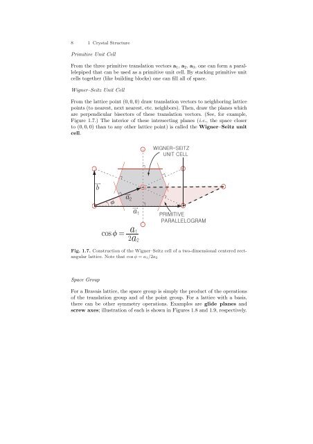
8 1 Crystal StructurePrimitive Unit CellFrom the three primitive translation vectors a 1 , a 2 , a 3 , one can form a parallelepipedthat can be used as a primitive unit cell. By stacking primitive unitcells together (like building blocks) one can fill all of space.Wigner–Seitz Unit CellFrom the lattice point (0, 0, 0) draw translation vectors to neighboring latticepoints (to nearest, next nearest, etc. neighbors). Then, draw the planes whichare perpendicular bisectors of these translation vectors. (See, for example,Figure 1.7.) The interior of these intersecting planes (i.e., the space closerto (0, 0, 0) than to any other lattice point) is called the Wigner–Seitz unitcell.ba aa cos =2 a Fig. 1.7. Construction of the Wigner–Seitz cell of a two-dimensional centered rectangularlattice. Note that cos φ = a 1 /2a 2Space GroupFor a Bravais lattice, the space group is simply the product of the operationsof the translation group and of the point group. For a lattice with a basis,there can be other symmetry operations. Examples are glide planes andscrew axes; illustration of each is shown in Figures 1.8 and 1.9, respectively.
1.1 Crystal Structure and Symmetry Groups 9Fig. 1.8. Glide plane of a two-dimensional lattice. Each unit cell contains six atomsGlide PlaneIn Figure 1.8, each unit cell contains six atoms and T 1/2 m x is a symmertryoperation even though neither T 1/2 nor m x are operation of the symmetrygroup by themselves.Screw AxisIn Figure 1.9, T 1/3 R 120 o is a symmerty operation even though T 1/3 and R 120 othemselves are not. Fig. 1.9. Screw axis. Unit cell contains three layersm and T 1 is the smallest translation.Occupied sites are shown by solid dots
10 1 Crystal StructureTwo-Dimensional Bravais LatticesThere are only five different types of two-dimensional Bravais lattices.1. Square lattice: primitive (P) one onlyIt has a = b and α = β = 90 o .2. Rectangular: primitive (P) and centered (C) onesThey have a ≠ b but α = β = 90 o .3. Hexagonal: primitive (P) one onlyIt has a = b and α = 120 o (β = 60 o ).4. Oblique: primitive (P) one onlyIt has a ≠ b and α ≠ 90 o .Three-Dimensional Bravais LatticesThere are fourteen different types of three-dimensional Bravais lattices.1. Cubic: primitive (P), body centered I), and face centered (F) onesFor all of these a = b = c and α = β = γ = 90 o .2. Tetragonal: primitive and body centered (I) onesFor these a = b ≠ c and α = β = γ = 90 o . One can think of them as cubiclattices that have been stretched (or compressed) along one of the cubeaxes.3. Orthorombic: primitive (P), body centered (I), face centered (F), and basecentered (C) onesFor all of these a ≠ b ≠ c but α = β = γ = 90 o . These can be thoughtof as cubic lattices that have been stretched (or compressed) by differentamounts along two of the cube axes.4. Monoclinic: primitive (P) and base centered (C) onesFor these a ≠ b ≠ c and α = β = 90 o ≠ γ. These can be thought of asorthorhombic lattices which have suffered shear distortion in one direction.5. Triclinic: primitive (P) oneThis has the lowest symmetry with a ≠ b ≠ c and α ≠ β ≠ γ.6. Trigonal:It has a = b = c and α = β = γ ≠ 90 o < 120 o . The primitive cell is arhombohedron. The trigonal lattice can be thought of as a cubic latticewhich has suffered shear distortion.7. Hexagonal: primitive (P) one onlyIt has a = b ≠ c and α = β = 90 o , γ = 120 o .1.2 Common Crystal Structures1. Cubic
1.2 Common Crystal Structures 11Fig. 1.10. Conventional unit cell of a simple cubic crystal of lattice constant aa) Simple cubic (sc): Figure 1.10For simple cubic crystal the lattice constant is a and the volume peratom is a 3 . The nearest neighbor distance is also a, and each atom hassix nearest neighbors. The primitive translation vectors are a 1 = aˆx,a 2 = aŷ, a 3 = aẑ.b) Body centered cubic (bcc): Figure 1.11If we take a unit cell as a cube of edge a, there are two atomsper cell (one at (0, 0, 0) and one at ( 12 , 1 2 , 2) 1 .) The atomic volumeis 1 2 a3 , and the nearest neighbor distance is √ 32a. Each atom haseight nearest neighbors. The primitive translations can be taken asa 1 = 1 2 a (ˆx + ŷ + ẑ), a 2 = 1 2 a (−ˆx + ŷ + ẑ), and a 3 = 1 2a (−ˆx − ŷ + ẑ).The parallelepiped formed by a 1 , a 2 , a 3 is the primitive unit cell (containinga single atom), and there is only one atom per primitive unitcell.Fig. 1.11. Conventional unit cell of a body centered cubic crystal of lattice constanta
12 1 Crystal Structurec) Face centered cubic (fcc): Figure 1.12If we take a unit cell as a cube of edge a, there are four atoms per cell;18 of one at each of the eight corners and 1 2of one on each of the sixfaces. The volume per atom is a34 ; the nearest neighbor distance is √ a 2,and each atom has 12 nearest neighbors. The primitive unit cell is theparallelepiped formed from the primitive translations a 1 = 1 2a (ˆx + ŷ),a 2 = 1 2 a (ŷ + ẑ), and a 3 = 1 2a (ẑ + ˆx).Fig. 1.12. Conventional unit cell of a face centered cubic crystal of lattice constantaAll three cubic lattices have the cubic group as their point group. Becausethe primitive translations are different, the simple cubic, bcc, and fcclattices have different translation groups.2. Hexagonala) Simple hexagonal: See Figure 1.13. Fig. 1.13. Conventional unit cell of a simple hexagonal crystal of lattice constantsa 1, a 2, and c
1.2 Common Crystal Structures 13b) Hexagonal close packed (hcp):This is a non-Bravais lattice. It contains two atoms per primitiveunit cell of the simple hexagonal lattice, one at (0,0,0) and the secondat ( 13 , 2 3 , 1 2). The hexagonal close packed crystal can be formed bystacking the first layer (A) in a hexagonal array as is shown in Figure1.14. Then, the second layer (B) is formed by stacking atoms in thealternate triangular holes on top of the first layer. This gives anotherhexagonal layer displaced from the first layer by ( 13 , 2 3 , 1 2). Then thethird layer is placed above the first layer (i.e., at (0,0,1)). The stackingis then repeated ABABAB · · · . If one stacks ABCABC · · · , where C isthe hexagonal array obtained by stacking the third layer in the otherset of triangular holes above the set B (instead of the set A), one getsan fcc lattice. The closest possible packing of the hcp atoms occurswhen c a = √ 8/3 ≈ 1.633. We leave this as an exercise for the reader.Zn crystalizes in a hcp lattice with a = 2.66Å and c = 4.96Å givingca ≈ 1.85, larger than the ideal c a value. Fig. 1.14. Stacking of layers A and B in a hexagonal close packed crystal of latticeconstants a 1 , a 2 , and c3. Zincblende Structure This is a non-Bravais lattice. It is an FCC withtwo atoms per primitive unit cell located at (0,0,0) and ( 14 , 1 4 , 4) 1 . Thestructure can be viewed as two interpenetrating fcc lattices displaced byone fourth of the body diagonal. Examples of the zincblende structureare ZnS (cubic phase), ZnO (cubic phase), CuF, CuCl, ZnSe, CdS, GaN(cubic phase), InAs, and InSb. The metallic ions are on one sublattice,the other ions on the second sublattice.4. Diamond Structure This structure is identical to the zincblende structure,except that there are two identical atoms in the unit cell. This structure(unlike zincblende) has inversion symmetry about the point ( 18 , 1 8 , 8) 1 .Diamond, Si, Ge, and gray tin are examples of the diamond structure.5. Wurtzite Structure This structure is a simple( hexagonal lattice withfour atoms per unit cell, located at (0,0,0), 13 , 2 3 , ) ( 12 , 0, 0,3( 8), and13 , 2 3 , ) 78 . It can be pictured as consisting of two interpenetrating hcp
14 1 Crystal Structurelattices separated by ( 0, 0, 3 8). In the wurtzite phase of ZnS, the Zn atomssit on one hcp lattice and the S atoms on the other. ZnS, BeO, ZnO(hexagonal phase), CdS, GaN (hexagonal phase), and AlN are materialsthat can occur in the wurtzite structure.6. Sodium Chloride Structure It consists of a face centered cubic latticewith a basis of two unlike atoms per primitive unit cell, located at (0,0,0)and ( 12 , 1 2 , 1 2). In addition to NaCl, other alkali halide salts like LiH, KBr,RbI form crystals with this structure.7. Cesium Chloride Structure It consists of a simple cubic lattice withtwo atoms per unit cell, located at (0,0,0) and ( 12 , 1 2 , 1 2). Besides CsCl,CuZn (β-brass), AgMg, and LiHg occur with this structure.8. Calcium Floride Structure It consists of a face centered cubic latticewith three atoms per primitive unit cell. The Ca ion is located at (0,0,0),the F atoms at ( 14 , 1 4 , (4) 1 and 34 , 3 4 , 4) 3 .9. Graphite Structure This structure consists of a simple hexagonal latticewith four atoms per primitive unit cell, located at (0,0,0), ( 2( ( 3 , 1 3 , 0) ,0, 0,12), and13 , 2 3 , 2) 1 . It can be pictured as two interpenetrating HCPlattices separated by ( 0, 0, 2) 1 . It therefore consists of tightly bonded planes(as is shown in Figure 1.15 below) stacked in the sequence ABABAB · · · .The individual planes are very tightly bound, but the interplanar bindingis rather weak. This gives graphite its well known properties, like easilycleaving perpendicular to the c axis. Fig. 1.15. Stacking of layers A and B in a graphite structureMiller indicesMiller indices are a set of three integers that specify the orientation of a crystalplane. The procedure for obtaining Miller indices of a plane is as follows:1. Find the intercepts of the plane with the crystal axes.2. Take the reciprocals of the three numbers.3. Reduce (by multiplying by the same number) this set of numbers to thesmallest possible set of integers.
1.2 Common Crystal Structures 15 Fig. 1.16. Intercepts of a plane with the crystal axesAs an example, consider the plane that intersects the cubic axes at A 1 , A 2 , A 3as shown in Figure 1.16. Then x i a i = OA i . The reciprocals of (x 1 , x 2 , x 3 )are ( x −11 , x−1 2 , ) x−1 3 , and the Miller indices of the plane are (h1 h 2 h 3 ) =p ( x −11 , x−1 2 , )( )x−1 3 , where (h1 h 2 h 3 ) are the smallest possible set of integerspx 1, p x 2, p x 3.Indices of a directionA direction in the lattice can be specified by a vector V = u 1 a 1 +u 2 a 2 +u 3 a 3 ,or by the set of integers [u 1 u 2 u 3 ] chosen to have no common integral factor. Forcubic lattices the plane (h 1 h 2 h 3 ) is perpendicular to the direction [h 1 h 2 h 3 ],but this is not true for general lattices.Packing fractionThe packing fraction of a crystal structure is defined as the ratio of the volumeof atomic spheres in the unit cell to the volume of the unit cell.Examples1. Simple cubic lattice:We take the atomic radius as R = a 2(then neighboring atoms just touch).The packing fraction p will be given by) 343p =π ( a2a 3 = π 6 ≈ 0.522. Body centered cubic ( lattice: √3Here we take R = 1 2 2), a i.e., half the nearest neighbor distance. Forthe non-primitive cubic cell of edge a, we have two atoms per cell givingp =) 3(2 × 4 3 π a √ 34a 3 = π √3 ≈ 0.688
16 1 Crystal Structure1.3 Reciprocal LatticeIf a 1 , a 2 , a 3 are the primitive translations of some lattice, we can define thevectors b 1 , b 2 , b 3 by the conditiona i · b j = 2πδ ij , (1.5)where δ ij = 0 if i is not equal to j and δ ii = 1. It is easy to see thata j × a kb i = 2πa i · (a j × a k ) , (1.6)where i, j, and k are different. The denominator a i · (a j × a k ) is simply thevolume v 0 of the primitive unit cell. The lattice formed by the primitive translationvectors b 1 , b 2 , b 3 is called the reciprocal lattice (reciprocal to thelattice formed by a 1 , a 2 , a 3 ), and a reciprocal lattice vector is given byUseful Properties of the Reciprocal LatticeG h1h 2h 3= h 1 b 1 + h 2 b 2 + h 3 b 3 . (1.7)1. If r = n 1 a 1 + n 2 a 2 + n 3 a 3 is a lattice vector, then we can write r asr = ∑ i(r · b i ) a i . (1.8)2. The lattice reciprocal to b 1 , b 2 , b 3 is a 1 , a 2 , a 3 .3. A vector G h from the origin to a point (h 1 , h 2 , h 3 ) of the reciprocal latticeis perpendicular to the plane with Miller indices (h 1 h 2 h 3 ).4. The distance from the origin to the first lattice plane (h 1 h 2 h 3 ) is d (h 1 h 2 h 3 ) =2π |G h | −1 . This is also the distance between neighboring {h 1 h 2 h 3 } planes.The proof of 3 is established by demonstrating that G h is perpendicular to theplane A 1 A 2 A 3 shown in Figure 1.16. This must be true if ( G h is perpendicularto both A 1 A 2 and to A 2 A 3 . But A 1 A 2 = OA 2 −OA 1 = pa2h 2− a 1h 1). Therefore(a2G h · A 1 A 2 = (h 1 b 1 + h 2 b 2 + h 3 b 3 ) · p − a )1, (1.9)h 2 h 1which vanishes. The same can be done for A 2 A 3 . The proof of 4 is establishedby noting thatd(h 1 h 2 h 3 ) = a 1 G h·h 1 |G h | .The first factor is just the vector OA 1 for the situation where p = 1, andthe second factor is a unit vector perpendicular to the plane (h 1 h 2 h 3 ). Sincea 1 · G h = 2πh 1 , it is apparent that d(h 1 h 2 h 3 ) = 2π |G h | −1 .
1.4 Diffraction of X-Rays 171.4 Diffraction of X-RaysCrystal structures are usually determined experimentally by studying howthe crystal diffracts waves. Because the interatomic spacings in most crystalsare of the order of a few Å’s (1Å = 10 −8 cm), the maximum information canmost readily be obtained by using waves whose wave lengths are of that orderof magnitude. Electromagnetic, electron, or neutron waves can be used tostudy diffraction by a crystal. For electromagnetic waves, E = hν, where Eis the energy of the photon, ν = c λis its frequency and λ its wave length,and h is Planck’s constant. For λ = 10 −8 cm, c = 3 × 10 10 cm/sec and h =6.6 × 10 −27 erg · sec, the photon energy is equal to roughly 2 × 10 −8 ergs or1.24 × 10 4 eV. Photons of energies of tens of kV are in the X-ray range. Forelectron waves, p = h λ ≃ 6.6 × 10⁻¹⁹ g · cm/sec when λ = 10 −8 cm. This givesE =p22m e, where m e ≃ 0.9 × 10 −27 g, of 2.4 × 10 −10 ergs or roughly 150eV.For neutron waves, we need simply replace m e by m n = 1.67 × 10 −24 g toobtain E = 1.3 × 10 −13 ergs ≃ 0.08eV. Thus neutron energies are of theorder of a tenth of an eV. Neutron scattering has the advantages that the lowenergy makes inelastic scattering studies more accurate and that the magneticmoment of the neutron allows the researcher to obtain information aboutthe magnetic structure. It has the disadvantage that high intensity neutronsources are not as easily obtained as X-ray sources.1.4.1 Bragg ReflectionWe have already seen that we can discuss crystal planes in a lattice structure.Assume that an incident X-ray is specularly reflected by a set of crystal planesas shown in Figure 1.17. Constructive interference occurs when the differencein path length is an integral number of wave length λ. It is clear that thisoccurs when2d sin θ = nλ, (1.10)where d is the interplane spacing, θ is the angle between the incident beamand the crystal planes, as is shown on the figure, and n is an integer. Equation(1.10) is known as Bragg’s law.INCIDENTWAVEREFLECTEDWAVEθθFig. 1.17. Specular reflection of X-rays by a set of crystal planes separated by adistance d