Hamworthy Gas Systems AS - Digital Ship
Hamworthy Gas Systems AS - Digital Ship
Hamworthy Gas Systems AS - Digital Ship

Create successful ePaper yourself
Turn your PDF publications into a flip-book with our unique Google optimized e-Paper software.
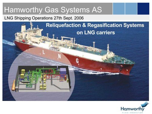
<strong>Hamworthy</strong> <strong>Gas</strong> <strong>Systems</strong> <strong>AS</strong><br />
LNG <strong>Ship</strong>ping Operations 27th Sept. 2006<br />
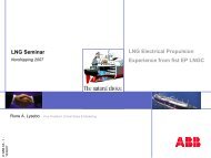
Reliquefaction & Regasification <strong>Systems</strong><br />
on LNG carriers
Agenda<br />
LNG <strong>Ship</strong>ping Operations Sept. 27, 2006<br />
• Organization & references<br />
• Why LNG reliquefaction systems ?<br />
• LNG onshore pilot plant and other recent references<br />
• LNG RS recent orders<br />
• Equipement<br />
• Contol principles<br />
• Next generations<br />
• LNG regasification
<strong>Hamworthy</strong> <strong>Gas</strong> <strong>Systems</strong> <strong>AS</strong><br />
�Owned by <strong>Hamworthy</strong> PLC with HQ in UK<br />
�<strong>Gas</strong> division located in Norway, approx 200 employees<br />
�International operations<br />
�UK, Norway, Denmark, Singapore, Germany, Korea, China,<br />
USA, India, Netherlands, Spain<br />
�Products mainly for production and transportation of oil & gas<br />
�<strong>Gas</strong> Division supplies high technology products for:<br />
�Cargo handling on gas carriers & FSO/FPSO’s<br />
�Reliquefaction systems for LPG, LEG & LNG<br />
�Inertgas- og Nitrogen-generators<br />
�Recovery of VOC from crude on shuttletankers/terminals<br />
�Condensation of VOC with 100% emission reduction<br />
�Regasification directly from LNG-carriers/FSRU<br />
�Test plant under construction in co-operation with ship owner<br />
�Onshore LNG production<br />
�Small scale plants e.g “Snurrevarden” (30 ton/day �)<br />
�Mini LNG-plants (Sintef) (8 – 40 ton/day)
<strong>Hamworthy</strong> plc<br />
Structure, products and sales<br />
<strong>Gas</strong><br />
<strong>Gas</strong> <strong>Systems</strong> Inert <strong>Gas</strong> <strong>Systems</strong><br />
40 years of gas system delivery references<br />
of liquid gas handling systems<br />
Process and systems design<br />
Pump <strong>Systems</strong><br />
General arrangement, fabrication and assembly<br />
<strong>Ship</strong>s integration<br />
Installation, commissioning and start-up<br />
Average sales last 3 years<br />
Wastewater<br />
Management <strong>Systems</strong><br />
Typical customers:<br />
Bergesen, Daewoo,<br />
Statoil, Exmar,<br />
ExxonMobil, <strong>Gas</strong>nor,<br />
Geogas, Hyundai, IHI,<br />
Kawasaki, Mitsui,<br />
Navion/Teekay, OSG,<br />
Pronav, Samsung,<br />
Solvang, Ugland, AP<br />
Møller, Sonatrac,<br />
Chevron, Leif Høegh.
LNG -Markets<br />
International gas trade by LNG tankers (1985)<br />
Alaska 1.4<br />
Exporting countries<br />
Existing LNG market<br />
50.9 bcm transported of which 73% to Japan<br />
0.7<br />
13.6<br />
Abu-Dhabi 3.1<br />
Brunei 6.9<br />
Indonesia 20<br />
Malaysia 5.9<br />
� LNG is a 40 years old industry dominated by few players and projects<br />
� Deregulation has opened up for new players and increased competition<br />
� New technology and players significant cost cuts in the LNG value chain
LNG -Markets<br />
International gas trade by LNG tankers (2004)<br />
Alaska 1.7<br />
Spot<br />
Exporting countries<br />
Existing LNG market<br />
Future LNG market<br />
177.5 bcm transported of which 43% to Japan<br />
13.9<br />
Brasil<br />
26.4<br />
12.6<br />
40.5<br />
India<br />
China<br />
70.7<br />
11.8
<strong>Hamworthy</strong> <strong>Gas</strong> <strong>Systems</strong><br />
LNG Global Demand - Projections<br />
400<br />
350<br />
300<br />
250<br />
200<br />
150<br />
100<br />
50<br />
0<br />
North America<br />
Europe<br />
Asia Pacific<br />
2000 2005 2010 2015<br />
Source: WoodMackenzie<br />
LNG trade<br />
projected to grow<br />
at an average of<br />
7% to 363,5<br />
mtpa by 2015<br />
Key contributing<br />
factors;<br />
• Demand for<br />
energy<br />
• Demand for<br />
cleaner fuel<br />
• Security of supply
<strong>Hamworthy</strong> <strong>Gas</strong> <strong>Systems</strong><br />
LNG Fleet Growth 1999 - 2010<br />
350<br />
300<br />
250<br />
200<br />
150<br />
100<br />
50<br />
7<br />
108<br />
12<br />
115<br />
1<br />
127<br />
10<br />
128<br />
14<br />
138<br />
24<br />
152<br />
18<br />
176<br />
19<br />
9<br />
194<br />
33<br />
222<br />
54<br />
255<br />
36<br />
309<br />
0<br />
1999 2001 2003 2005 2007 2009<br />
Basis no scrapping<br />
Based on orders as at 30 April 2006 Source: Drewry & Clarkson<br />
3<br />
345<br />
Orderbook<br />
Deliveries<br />
Fleet start
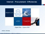
The LNG value chain<br />
LNG: a mean for concentrating & transporting energy (1/600 th of volume in gaseous state)<br />
Small scale Liquefaction plants<br />
Transportation: reliquefaction<br />
Floating regasification systems<br />
18-24% 32-36% 29-32% 14-15%
<strong>Hamworthy</strong> <strong>Gas</strong> <strong>Systems</strong> <strong>AS</strong><br />
Forward Orderbook: LNG systems as off August 2006<br />
Client Type Site/<strong>Ship</strong>owner Delivery<br />
DSME 4 LNG Reliquefaction Plants (QG II ) Pronav 2006<br />
Hyundai 2 LNG Reliquefaction Plants (QG II) OSG 2006<br />
Samsung 2 LNG Reliquefaction Plants (QG II) OSG 2006<br />
Samsung 4 LNG Reliquefaction Plants (Rasgas III) Teekay 2006/07<br />
G<strong>AS</strong>NOR 1 LNG Plant 240 t LNG/day <strong>Gas</strong>nor, Kollsnes 2007<br />
Hyundai 3 LNG Reliquefaction Plants (Rasgas III) J5 NYK) 2006/07<br />
DSME 5 LNG Reliquefaction Plants (Rasgas III) J5 (MOL,KL) 2007<br />
Hoegh LNG 1 LNG Regasification plant prototype 2006<br />
Samsung 6 Regasification skids to 2 SRV’s Hoegh LNG/MOL 2008<br />
HHI 3 LNG Reliquefaction Plants (QGIII) QGTC 2008/09
Agenda<br />
LNG <strong>Ship</strong>ping Operations Sept. 27, 2006<br />
• Organization & references<br />
• Why LNG reliquefaction systems?<br />
• LNG onshore pilot plant and other recent references<br />
• LNG RS recent orders<br />
• Equipement<br />
• Contol principles<br />
• Next generations<br />
• LNG regasification
LNG carriers’ traditional propulsion system<br />
Why change ?<br />
Low efficiency of turbines<br />
high fuel consumption/cost<br />
Valuable cargo used as fuel<br />
Lack of crew to operate<br />
steam turbines<br />
Power required by large<br />
LNG carriers at boundary of<br />
existing turbine design<br />
Limited redundancy<br />
2 suppliers<br />
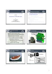
• Boil-Of-<strong>Gas</strong> (BOG) is a result of the LNG warming up during transportation.<br />
• All BOG now used as fuel in steam turbine propulsion systems.<br />
• Reliability in existing system considered to be very high.<br />
• Proven system with low lubrication and maintenance cost
Alternative to to-days practice<br />
BOG reliquefaction<br />
system in combination<br />
with 2 stroke diesel<br />
engine(s)<br />
The Moss RS reliquefies<br />
BOG and send LNG<br />
back to the cargo tanks<br />
Results in<br />
economical and<br />
technical advantages<br />
<strong>Hamworthy</strong> has<br />
worldwide rights to the<br />
patented Moss RS TM
LNG Reliquefaction system<br />
Two principle different solutions available for LNG carrier propulsion:<br />
1. Use BOG & LNG as fuel e.g steam turbines, dual-fuel diesel electric, gas engines<br />
2. Use efficient slow speed diesel engines and BOG reliquefaction, sell all LNG loaded onboard<br />
LNG level<br />
in tanks<br />
Maximum<br />
Minimum<br />
Ballast<br />
Pattern for ship’s using BOG & LNG as fuel for propulsion<br />
Minimum heel required for cool down of tanks<br />
Laden Ballast<br />
Fuel used during roundtrip<br />
(Natural BOG & forced)<br />
Additional LNG delivered<br />
with Slow Speed diesel and<br />
BOG Reliquefaction System<br />
27.08.03
LNG Reliquefaction system<br />
LNG & HFO prices<br />
$/mBTU<br />
7,00<br />
6,00<br />
5,00<br />
4,00<br />
3,00<br />
2,00<br />
1,00<br />
0,00<br />
1997 1998 1999 2000 2001 2002 2003 2004 2005<br />
Future price<br />
difference ??<br />
Japan CIF<br />
EU CIF<br />
US Henry Hub<br />
HFO price<br />
HFO always been competitive compared with natural gas prices in Europe, USA and Japan.<br />
<strong>Gas</strong> price in Europe and USA in average (1994-2001) 110% higher than HFO prices<br />
Japanese gas prices have been 160 % of HFO prices<br />
The gas prices have increased considerably compared with HFO the last years<br />
27.08.03
Propulsion alternatives & energy consumptions<br />
Source: Man B&W<br />
50<br />
40<br />
30<br />
Propulsion type Relative energy cons.<br />
Main + aux system (%)<br />
Slow Speed diesel 66<br />
Diesel electric 72<br />
<strong>Gas</strong> turbines 84<br />
Conventional steam turbine 100<br />
Best efficiency,<br />
Lowest total fuel consumption,<br />
Lowest value fuel (HFO)<br />
Improved efficiency,<br />
High value fuel (LNG or MDO)<br />
Improved efficiency,<br />
High value fuel (LNG)<br />
Lowest efficiency,<br />
Highest total fuel consumption,<br />
High value fuel (LNG) + HFO<br />
Example made by<br />
ship owner
LNG Reliquefaction system<br />
Slow speed diesel and reliquefaction system (RS) compared with alternatives:<br />
Lowest total operating cost (efficient propulsion using HFO, maintenance and lube oil)<br />
Additional sale of LNG<br />
4,00 %<br />
3,50 %<br />
3,00 %<br />
2,50 %<br />
2,00 %<br />
1,50 %<br />
1,00 %<br />
0,50 %<br />
0,00 %<br />
Relative increase annual LNG deliveries<br />
LNG sales price 3.5 $/Mbtu<br />
3.4 M$<br />
4.3 M$<br />
Steam turbine Diesel<br />
5.5 M$<br />
Avg. BOR 0,08%/day Avg. BOR 0,10%/day Avg. BOR 0,12%/day<br />
Slow speed diesel and RS competitive, in particular for large LNG Carriers<br />
Traditional size vessels, reason to believe steam still lowest
Agenda<br />
LNG <strong>Ship</strong>ping Operations Sept. 27, 2006<br />
• Organization & references<br />
• Why LNG reliquefaction systems ?<br />
• LNG onshore pilot plant and other recent<br />
references<br />
• LNG RS recent orders<br />
• Equipement<br />
• Contol principles<br />
• Next generations<br />
• LNG regasification
Snurrevarden LNG plant - Norway<br />
<strong>Hamworthy</strong> delivered a free<br />
standing mini LNG plant in<br />
March 2003 based on the<br />
same principles as the<br />
re-liquefaction system.<br />
The mini LNG plant uses<br />
same type of equipment<br />
as for re-liquefaction<br />
systems.<br />
Control functions are also<br />
much similar.<br />
The plant is designed for<br />
unmanned operation
LNG Reliquefaction system<br />
Snurrevarden LNG plant has resulted in awards of – 23 LNG RS for LNG Carriers !<br />
Onshore<br />
Main equipment<br />
plant vs<br />
same<br />
installation<br />
as for<br />
on<br />
the<br />
LNG<br />
ships;<br />
carrier;<br />
LNG<br />
Same<br />
production<br />
make of 3<br />
capacity<br />
stage centrifugal<br />
60 ton/day<br />
compressor<br />
(2500kg/hr)<br />
with expander for the refrigeration<br />
cycle<br />
Pre-treatment of feed gas, removal of CO2 & water (not on LNG carriers)<br />
Same cold box type (plate fin heat exchanger)<br />
Feed gas pressure to be reduced – no need for low duty compressors Storage tank<br />
Same control system principles<br />
<strong>Gas</strong> engine<br />
Cooling cycle<br />
compressor<br />
Instrument air &<br />
Nitrogen<br />
LPG separator &<br />
<strong>Gas</strong> condensation (LNG)<br />
H2O removal<br />
CO2 removal
LNG Reliquefaction system<br />
Approval in principle from DNV, Lloyds, BV, ABS
LNG Reliquefaction system<br />
Proven or unproven!<br />
� The system only use proven components - first class, high quality with extensive<br />
reference<br />
Process/system<br />
System<br />
status<br />
Risk<br />
area<br />
� Low duty compressors used on all LNG carriers<br />
Comfort factors<br />
Risk mitigation<br />
� Cold box (plate fin heat exchanger) widely used in onshore cryogenic installations.<br />
� Refrigeration & cargo cycle have been proven in operation<br />
� Analysis concludes 99.98 % availability<br />
� Approval in principle by several class societies<br />
� Independant HAZOP/HAZID with owners & class<br />
� <strong>Hamworthy</strong> has supplied a small scale LNG plant based on same principles.<br />
Operational experience since Mar 2003.
Agenda<br />
LNG <strong>Ship</strong>ping Operations Sept. 27, 2006<br />
• Organization & references<br />
• Why LNG reliquefaction systems ?<br />
• LNG onshore pilot plant and other recent references<br />
• LNG RS recent orders<br />
• Equipement<br />
• Contol principles<br />
• Next generations<br />
• LNG regasification
LNG Re-liquefaction<br />
- Refrigeration system<br />
- Redundancy considerations<br />
- Capacity control<br />
- Separation of N 2–rich vent gas<br />
- Functional diagrams<br />
- N 2 compander<br />
- Cryogenic heat exchangers<br />
- BOG compressor<br />
- LNG pump skid<br />
- N 2 booster skid<br />
Equipment and control system<br />
is defined and selected in order<br />
to ensure the best possible<br />
operation of the re-liquefaction<br />
system in accordance with<br />
class regulations
LNG Reliquefaction system<br />
Redundancy considerations<br />
IACS Rules for Redundancy for RS<br />
� Spare capacity of RS unit, or<br />
� Auxiliary boiler(s) for BOG, or<br />
� <strong>Gas</strong> oxidiser (GCU) for the BOG, or<br />
� Controlled venting<br />
Different configurations/alternatives<br />
• 2x100% capacity with 1 cold box<br />
• 1x100% capacity with gas oxidizer (GCU)<br />
• QGII ;<br />
2x100% capacity with GCU<br />
• Different configurations studied for new<br />
projects resulting in operational flexibility<br />
BOG FEED<br />
COOLING<br />
WATER<br />
+100<br />
0<br />
-100<br />
-200<br />
+100<br />
-100<br />
-200<br />
SUCTION THROTTLE<br />
0<br />
MAX<br />
MIN<br />
+100<br />
-100<br />
-200<br />
2 3<br />
1 E<br />
0<br />
NITROGEN<br />
RESERVOIR<br />
+100<br />
0<br />
-100<br />
-200<br />
RECYCLING<br />
BY-P<strong>AS</strong>S<br />
+100<br />
0<br />
-100<br />
-200<br />
+100<br />
0<br />
-100<br />
-200<br />
+100<br />
0<br />
-100<br />
-200<br />
MAX<br />
MIN<br />
+100<br />
0<br />
-100<br />
-200<br />
VENT<br />
+100<br />
0<br />
-100<br />
-200<br />
TO TANKS
LNG Re-liquefaction<br />
The Re-liquefaction system is based on the N 2-Brayton cycle<br />
This system has proven to be advantageous for several<br />
reasons:<br />
- simplicity (single component, single phase refrigerant)<br />
- short response time for capacity adjustments<br />
- dynamic type (centrifugal) machinery can be employed<br />
The <strong>Hamworthy</strong><br />
supplied<br />
Moss TM RS is a<br />
patent protected<br />
system.
Process Description – Cargo Cycle<br />
� BOG from the cargo<br />
tanks (1.06-1.15 bar a)<br />
by conventional LD<br />
compressors.<br />
� To enable stable<br />
temp at inlet cold<br />
box, BOG is<br />
pre-cooled upstream<br />
compressors<br />
� Discharge pressure from BOG compressor is<br />
4,5 bar and the BOG is cooled and condensed to<br />
LNG at this pressure in a 3-stream plate-fin<br />
cryogenic heat exchanger (cold box).<br />
Vent or GCU<br />
�Non-condensibles,<br />
mainly N 2 , are removed<br />
in a separator ( 4,5 bar)<br />
and exited to a flare<br />
(GCU) or vent mast.<br />
Partial reliq (if N 2<br />
>12%) results in ;<br />
-reduced power req.<br />
-tank pressure control<br />
� From the separator,<br />
the LNG flows back to<br />
the cargo tanks
Process Description – Nitrogen Cycle<br />
The RS system needs to have sufficient capacity to cater for heat ingress to the cargo tanks,<br />
vapour header and LBOG piping, in adition to heat introduced by BOG compressors<br />
� N 2 at 13.5 bar<br />
compressed to 57 bar<br />
in 3-stage centrifugal<br />
compressor with water<br />
cooling.<br />
�The gas is led to the “warm” part of the cryogenic<br />
H/E where it is pre-cooled (–110°C) and send to the<br />
expander<br />
�The gas expanded to<br />
a pressure of 14.5 bar<br />
and temp of –163°C.<br />
<strong>Gas</strong> then introduced<br />
into the “cold” part of<br />
the cryogenic H/E<br />
where it cools and<br />
reliquefies the boil-off<br />
gas to LNG.
<strong>Hamworthy</strong> <strong>Gas</strong> <strong>Systems</strong> <strong>AS</strong><br />
LNG Reliquefaction systems<br />
23 reliquefaction units contracted<br />
with <strong>Hamworthy</strong> so far…
<strong>Hamworthy</strong> <strong>Gas</strong> <strong>Systems</strong> <strong>AS</strong><br />
LNG Reliquefaction systems
Normal Cargo Handling Operations<br />
� Operations with the Re-Liquefaction plant<br />
in use;<br />
� Laden voyage – normal boil off rate<br />
� Laden voyage + extra BOG<br />
� Ballast voyage<br />
� Cooling down during ballast voyage<br />
before loading<br />
� One tank operations at sea and Re-Liq<br />
on remaining tanks<br />
� Warming up<br />
� <strong>Gas</strong> freeing<br />
� Aerating<br />
� Drying<br />
� Inerting<br />
� <strong>Gas</strong>sing up<br />
� Cooling down<br />
� <strong>Gas</strong> freeing/warm gas through BOG<br />
compressors to GCU
Dynamic simulation model of RS<br />
Pre-qualification of <strong>Hamworthy</strong> as<br />
a supplier to Qatar <strong>Gas</strong> involved ;<br />
- extensive process discussions<br />
- qualifications of our sub-suppliers<br />
and<br />
- development of a Dynamic model.<br />
Typical dynamic simulation cases;<br />
1. Start-up from warm condition<br />
2. Normal operation<br />
3. Stand-by operation<br />
4. Ballast (40% capacity,<br />
warm BOG (-40degC))<br />
5. Normal shut down<br />
6. Emergency shut down<br />
7. Varying N2 content in BOG
LNG RS simulator<br />
Overview screen
Agenda<br />
LNG <strong>Ship</strong>ping Operations Sept. 27, 2006<br />
• Organization & references<br />
• Why LNG reliquefaction systems ?<br />
• LNG onshore pilot plant and other recent references<br />
• LNG RS recent orders<br />
• Equipement<br />
• Contol principles<br />
• Next generations<br />
• LNG regasification
<strong>Hamworthy</strong> <strong>Gas</strong> <strong>Systems</strong> <strong>AS</strong><br />
LNG Reliquefaction project<br />
Awarded new contract 9 Sep 05<br />
New add. capacity 84000 tons/year<br />
Ready for operation Feb 2007
LNG Reliquefaction system<br />
New concepts with<br />
15-20 % reduction in<br />
power consumption<br />
developed
Improvements on power consumption<br />
What distinguishes double expander from current Qflex design,<br />
Mark I?<br />
Three major changes:<br />
1. New compander design<br />
1. New cold box geometry<br />
1. New precooling<br />
concept<br />
RESULT:<br />
Typically 15-20% decrease in<br />
specific liquefaction energy (kWh/kg LBOG)<br />
Patent pending
Further improvements – ambient BOG comp<br />
What about Mark III ?<br />
Proposed changes:<br />
1. BOG compressor (3 stages)<br />
works under ambient<br />
temperatures<br />
2. BOG compressor inter- &<br />
after- coolers<br />
3. Removes heat with cooling<br />
water from high temp BOG<br />
4. Can down size Compander<br />
5. Reduce exergy losses in<br />
cold box<br />
Patent pending
Power consumption example Qmax<br />
1 expander versus 2 expander solution verses Mark III<br />
Power cons.<br />
1 exp solution<br />
N2 compander<br />
BOG compressor<br />
Sum<br />
Power cons.<br />
1 exp solution<br />
6356<br />
462<br />
6818<br />
Power cons.<br />
2 exp solution<br />
kw<br />
5406<br />
447<br />
5853<br />
7000<br />
6000<br />
5000<br />
4000<br />
3000<br />
2000<br />
1000<br />
0<br />
Power cons.<br />
Mark III<br />
Power consumption<br />
- 14%<br />
4441<br />
1014<br />
5454<br />
- 20%<br />
1 Exp 2 Exp Amb. BOG
Power consumption example Qflex<br />
1 expander Mark I versus Mark III<br />
Power consumption<br />
N2 compander<br />
BOG compressor<br />
Sum<br />
Power cons.<br />
1 exp solution Mark I<br />
4859<br />
332<br />
5191<br />
5200<br />
5000<br />
4800<br />
4600<br />
4400<br />
4200<br />
4000<br />
Power cons.<br />
Mark III<br />
Power Consumption<br />
- 14%<br />
3623<br />
784<br />
4407<br />
-15%<br />
Mark I Mark III
<strong>Hamworthy</strong> <strong>Gas</strong> <strong>Systems</strong> <strong>AS</strong><br />
Kollsnes II<br />
New refrigerant cycle with double expander<br />
will be commissioned and put in operation<br />
February 2007.<br />
Retrofit installation on existing LNG production site
LNG Reliquefaction system<br />
Summary<br />
• Slow speed diesel engines in combination with<br />
reliquefaction system, results in improved<br />
economy<br />
• LNG business is conservative and typical attitude<br />
has for a long time been;<br />
“We do not want to be the first, but first to follow”<br />
This is now possible !<br />
• Expect several alternative propulsion systems to<br />
be used in the future.<br />
Selection dependant on trade, size of vessels,<br />
charterer’s and owners’ preference, etc<br />
• <strong>Hamworthy</strong> continues improving the system;<br />
- Reduced power consumption<br />
- Improved redundancy configurations<br />
- Improved project execution models
Agenda<br />
LNG <strong>Ship</strong>ping Summit 2006<br />
• Organization & references<br />
• Why LNG reliquefaction systems ?<br />
• Snurrevarden LNG and other recent references<br />
• LNG Reliquefaction <strong>Systems</strong><br />
• Equipement<br />
• Contol principles<br />
• Next generation Mark III<br />
• LNG regasification
LNG regasification system<br />
• Increased import &<br />
spot/short term<br />
LNG trading<br />
in the future<br />
• Capacity in existing<br />
import terminals<br />
booked/limited<br />
• Permission to build<br />
new land terminals<br />
in US/Europe<br />
difficult<br />
• Vaporization plant<br />
onboard LNG<br />
carriers or Floating<br />
Storage Units will<br />
not need “terminals”<br />
Not in my back yard !!
LNG regasification system<br />
Regasification units<br />
on;<br />
Process/system<br />
• Floating Storage<br />
Regasification Unit<br />
(FSRU) permanently<br />
anchored receiving<br />
LNG from LNG<br />
carriers<br />
or<br />
• Shuttle Regasification<br />
Vessels overlapping<br />
at unloading site in<br />
order to ensure<br />
continuous send-out<br />
3 alternative <strong>Hamworthy</strong> Regass systems: unit<br />
- Steam based (closed loops)<br />
- Cascade type using seawater and propane<br />
with or without phase change of propane<br />
- Pure seawater based
<strong>Hamworthy</strong> LNG regasification system<br />
What is a shuttle regasifcation vessel ?
LNG Regasification Unit<br />
Steam/glycol system<br />
Heat to the regas process is taken<br />
from the onboard steam boilers<br />
Pressure & capacity ranges;<br />
40-130 bar<br />
50-1100 t/hr<br />
LNG booster pumps<br />
Printed circuit<br />
heat exchanger<br />
(steam against<br />
water-glycol mix)<br />
Shell & tube<br />
heat exchanger<br />
(water-glycol mix<br />
against LNG)<br />
Water glycol mix<br />
circulation pump
LNG Regasification Unit<br />
Cascade (propane/seawater) system<br />
Propane in closed loop heat LNG<br />
Heat to the regas process from ambient seawater<br />
Reduced regas fuel consumptions<br />
Same pressure & capacity ranges<br />
LNG/seawater<br />
heat exchanger<br />
<strong>Gas</strong> out<br />
Propane /<br />
Seawater HX<br />
(plate type in titanium)<br />
Seawater In<br />
Seawater out<br />
Propane pump<br />
LNG/propane<br />
heat exchanger<br />
(PCHE)<br />
<strong>Gas</strong> in<br />
LNG booster<br />
pump
<strong>Hamworthy</strong> LNG regasification system<br />
Neptune project outside Boston, US (Hoegh LNG for Suez)
<strong>Hamworthy</strong> LNG regasification system<br />
Neptune project outside Boston, US (Hoegh LNG for Suez)
<strong>Hamworthy</strong> <strong>Gas</strong> <strong>Systems</strong> <strong>AS</strong><br />
RE-G<strong>AS</strong>IFICATION TEST PLANT<br />
• Propane 2-phase solution<br />
• Water/Glycol solution<br />
• Placed at Kollsnes, Bergen Norway<br />
• Capacity: abt 200 kg/h (scale abt 1:1000)<br />
• Currently under final commissioning<br />
• Estimated official test run mid September
<strong>Hamworthy</strong><br />
Thank you for<br />
your patience !