Model P4800 System Processor Installation Guide - AVsuperstore.com
Model P4800 System Processor Installation Guide - AVsuperstore.com
Model P4800 System Processor Installation Guide - AVsuperstore.com

Create successful ePaper yourself
Turn your PDF publications into a flip-book with our unique Google optimized e-Paper software.
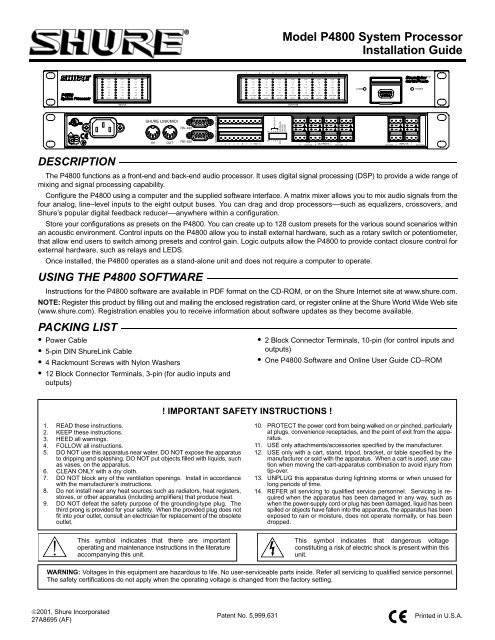
<strong>Model</strong> <strong>P4800</strong> <strong>System</strong> <strong>Processor</strong><strong>Installation</strong> <strong>Guide</strong>DESCRIPTIONThe <strong>P4800</strong> functions as a front-end and back-end audio processor. It uses digital signal processing (DSP) to provide a wide range ofmixing and signal processing capability.Configure the <strong>P4800</strong> using a <strong>com</strong>puter and the supplied software interface. A matrix mixer allows you to mix audio signals from thefour analog, line–level inputs to the eight output buses. You can drag and drop processors––such as equalizers, crossovers, andShure’s popular digital feedback reducer––anywhere within a configuration.Store your configurations as presets on the <strong>P4800</strong>. You can create up to 128 custom presets for the various sound scenarios withinan acoustic environment. Control inputs on the <strong>P4800</strong> allow you to install external hardware, such as a rotary switch or potentiometer,that allow end users to switch among presets and control gain. Logic outputs allow the <strong>P4800</strong> to provide contact closure control forexternal hardware, such as relays and LEDS.Once installed, the <strong>P4800</strong> operates as a stand-alone unit and does not require a <strong>com</strong>puter to operate.USING THE <strong>P4800</strong> SOFTWAREInstructions for the <strong>P4800</strong> software are available in PDF format on the CD-ROM, or on the Shure Internet site at www.shure.<strong>com</strong>.NOTE: Register this product by filling out and mailing the enclosed registration card, or register online at the Shure World Wide Web site(www.shure.<strong>com</strong>). Registration enables you to receive information about software updates as they be<strong>com</strong>e available.PACKING LIST Power Cable 5-pin DIN ShureLink Cable 4 Rackmount Screws with Nylon Washers 12 Block Connector Terminals, 3-pin (for audio inputs andoutputs) 2 Block Connector Terminals, 10-pin (for control inputs andoutputs) One <strong>P4800</strong> Software and Online User <strong>Guide</strong> CD–ROM! IMPORTANT SAFETY INSTRUCTIONS !1. READ these instructions.2. KEEP these instructions.3. HEED all warnings.4. FOLLOW all instructions.5. DO NOT use this apparatus near water. DO NOT expose the apparatusto dripping and splashing. DO NOT put objects filled with liquids, suchas vases, on the apparatus.6. CLEAN ONLY with a dry cloth.7. DO NOT block any of the ventilation openings. Install in accordancewith the manufacturer’s instructions.8. Do not install near any heat sources such as radiators, heat registers,stoves, or other apparatus (including amplifiers) that produce heat.9. DO NOT defeat the safety purpose of the grounding-type plug. Thethird prong is provided for your safety. When the provided plug does notfit into your outlet, consult an electrician for replacement of the obsoleteoutlet.10. PROTECT the power cord from being walked on or pinched, particularlyat plugs, convenience receptacles, and the point of exit from the apparatus.11. USE only attachments/accessories specified by the manufacturer.12. USE only with a cart, stand, tripod, bracket, or table specified by themanufacturer or sold with the apparatus. When a cart is used, use cautionwhen moving the cart-apparatus <strong>com</strong>bination to avoid injury fromtip-over.13. UNPLUG this apparatus during lightning storms or when unused forlong periods of time.14. REFER all servicing to qualified service personnel. Servicing is requiredwhen the apparatus has been damaged in any way, such aswhen the power-supply cord or plug has been damaged, liquid has beenspilled or objects have fallen into the apparatus, the apparatus has beenexposed to rain or moisture, does not operate normally, or has beendropped.This symbol indicates that there are importantoperating and maintenance instructions in the literatureac<strong>com</strong>panying this unit.This symbol indicates that dangerous voltageconstituting a risk of electric shock is present within thisunit.WARNING: Voltages in this equipment are hazardous to life. No user-serviceable parts inside. Refer all servicing to qualified service personnel.The safety certifications do not apply when the operating voltage is changed from the factory setting.©2001, Shure Incorporated27A8695 (AF)Patent No. 5,999,631Printed in U.S.A.
COMPUTER CONNECTIONSRS–232Connect the COM port on your <strong>com</strong>puter to one of the 9-pin RS-232 connectors on the <strong>P4800</strong> device using a male-to-female serialcable, as shown in Figure 4.NOTE: Use only a standard, 9-pin, RS-232 cable wired straight-through. Other types of serial cables that use fewer pins or crossedwires will not work.Front PanelRS-232 Serial PortRS–232, 9-PIN SERIAL CABLE(MALE-TO-FEMALE)Rear PanelRS-232 Serial PortRS–232 SERIAL PORT CONNECTIONFigure 4RS–422For cable lengths of 50 ft. or more, use an RS–422 serial connection. Unless you have an RS–422 serial port on your <strong>com</strong>puter, youwill need an adapter for your <strong>com</strong>puter’s RS–232 COM port, as shown in Figure 5.<strong>P4800</strong> RS-422 SERIALPORTRS-232SERIAL PORTRS–232 toRS-422ADAPTERRS–422 SERIAL PORT CONNECTIONFigure 5NetworkedUp to 16 ShureLink devices, including <strong>P4800</strong>s, DP11EQs, DFR11EQs, and UA888s can be linked and controlled from one <strong>com</strong>puter.Connect the ShureLink IN and ShureLink OUT of each device using 5-pin DIN cables (like the one supplied with the <strong>P4800</strong>), as shownin Figure 6. The last device in the chain must be connected to the first device (the one connected directly to the <strong>com</strong>puter) toform a loop.(Device ID 0)(Device ID 12) (Device ID 9)DIP Switch Settings for Networked Devices Make sure the SHURE LINK/MIDI DIP switch is in the UPposition (see Figure 7). Assign each device a unique Device ID using DIP Switches1–4 (See Table 1).IMPORTANT: Each device must have a unique Device ID number.ShureLinkActivatedDevice IDDIP SwitchesDIP SWITCH SETTINGS FOR NETWORKED DEVICESFigure 7NETWORKED CONNECTIONFigure 6Table 1. Device ID SettingsDevice Device ID ID 0 8 1 9 2 10 3 11 4 12 5 13 6 14 7 15* * Default4
COMMUNICATIONS LEDThe <strong>com</strong>munications LED illuminates wheneverthere is activity between the device and the PC.Communications LEDCONTROL PIN CONNECTIONSCOMMUNICATIONS LEDFigure 8The control pins on the back of the <strong>P4800</strong> unit connect to switches, potentiometers, LED indicators, and third-party control hardware.Control Input pins can be used to change presets, adjust gain, and mute channels. Logic Output pins can be used to power LEDs orrelays in response to preset changes or muted channels.NOTE: Control pins must be configured to match the attached control hardware using the <strong>P4800</strong> software (Refer to the Control Pinsection of the online help or the online user guide included on the <strong>P4800</strong> CD ROM).Determining Pin AllocationsYou must begin by determining which pins to use for presetcontrol and preset logic output. These pins will connect to externalhardware that switches presets or receives logic outputabout the current preset.Any remaining, unallocated pins can then be used for processorcontrol and processor logic output to adjust gain, mute channels,or power LEDs and relays.The number of pins needed for preset control and preset logicoutput depends on the type of control hardware and the numberof presets. Use the following guidelines:One-to-One: Use one pin for each preset, starting at Pin 1and proceeding to the right. You must use consecutive pins.Binary: Use the pin numbers as listed in Table 2.Custom Switch: Use Pin 1 for up to 10 presets.Control Input PinsPreset ControlShure Proprietary Switches:DRS100–Use Pin 1 for up to 10 presets.DRS41–Use Pin 1 for 4 presets and Pin 2 for gain control.Table 2. Binary Control Pin AllocationNumber of Presets Pin Numbers2 14 1 and 28 1–316 1–432 1–564 1–6128 1–7Figure 9 shows examples of how to connect different types of preset control hardware to the Control Input pins. When properly configured,the <strong>P4800</strong> changes to the appropriate preset in response to the switch.One-to-one Configuration(Each pin represents one preset)Binary ConfigurationCustom Switch Configuration*GroundGroundGround* See Table 3 for resistor values. A two-conductor, unshielded cable,such as a Belden 8442, is re<strong>com</strong>mended. The total resistance of thecable run must be less than 100 ohms.WIRING CONTROL INPUT PINS FOR PRESET CONTROLFigure 9Table 3. Custom Switch Resistor ValuesPRESETRESISTOR VALUE1 97–202 kΩ2 44–60 kΩ3 26–32 kΩ4 17–20 kΩ5 11.3–13.6 kΩ6 7.8–9.3 kΩ7 5.2–6.3 kΩ8 3.3–4.1 kΩ9 1.9–2.5 kΩ10 0.63–1.1 kΩA resistor with a value within the specifiedrange switches the device to thecorresponding preset.5
<strong>Processor</strong> ControlFigure 10 shows examples of how to connect a potentiometer or a switch to the Control Input pins. The <strong>P4800</strong> can then be configuredto respond to the switch or potentiometer by changing gain settings or muting channels.100K Potentiometer(Audio Taper)Logic Output PinsPreset Logic OutputGroundSwitch (momentary or toggle)WIRING CONTROL INPUT PINS FOR PROCESSOR CONTROLFigure 10Figure 11 shows examples of how to wire Logic Output pins to LEDs, relays, or third-party logic hardware. You can then configure the<strong>P4800</strong> to ground the appropriate pins to reflect the active preset.500Ω Resistor*One-to-One/BinaryConfigurations5V dc RelaysLEDs*Necessary for LEDsnot rated for 5V.Binary ConfigurationBINARYLOGICHARDWARE+5VWIRING LOGIC OUTPUT PINS FOR PRESET LOGIC OUTPUTFigure 11<strong>Processor</strong> Logic OutputFigure 12 shows examples of how to wire Logic Output pins to LEDs or relays. You can then configure the <strong>P4800</strong> to ground theappropriate pins to reflect muted channels.5V dc Relay500Ω Resistor*LED*Necessary for LEDsnot rated for 5V.WIRING LOGIC OUTPUT PINS FOR PROCESSOR LOGIC OUTPUTFigure 126
MIDI CONTROLThe MIDI port on the <strong>P4800</strong> allows you to use a MIDI controllerto change presets and perform other <strong>P4800</strong> functions. For example,a standard MIDI message for PROGRAM CHANGEwould cause a preset change in a device. The message mustcontain the Device ID and the number of the desired preset.Consult the Online User <strong>Guide</strong> (on the included CD–ROM) fordetails on MIDI control messaging.Networked MIDI ControlUp to 16 devices can be linked to one MIDI controller. Connectthe ShureLink/MIDI IN and ShureLink/MIDI OUT of each deviceusing 5 pin DIN cables (like the one supplied) as shown in Figure14. The last device in the chain must be connected to the firstdevice to form a loop. The MIDI controller can be placed anywherein the loop.MIDI ConnectorsMIDI PORTFigure 13DIP Switch Settings for MIDI Control Set the SHURELINK / MIDI DIP switch to the down (“DN”)position (MIDI) as shown in Figure 15. Assign each device a unique Device ID using DIP switches1–4 (See Table 1, Page 4).MIDI Controller(Device ID 12) (Device ID 9)NETWORKED MIDI CONNECTIONFigure 14SPECIFICATIONSFrequency Response20 Hz to 20 kHz +1, –3 dBDynamic Range100 dB minimum, A-weighted, 20 Hz to 20 kHzSampling Rate48 kHzDigital-to-Analog, Analog-to-Digital Conversion24-bitImpedanceInput: 10 kΩOutput: 120 ΩInput Clipping Level+26 dBu minimumOutput Clipping Level+22 dBu+2 dBu (with 20 dB pad)Total Harmonic Distortion< 0.05%, +4 dBu, 20 Hz to 20 kHzPropagation Delay from Input to Output
431.0 mm(16–31/32 IN.)4.76 mm(3/16 IN.)443.7 mm(17–15/32 IN.)482.6 mm(19 IN.)CertificationsUL Listed and cUL Listed to UL 6500 and CSA E60065. Authorizedunder Verification provision of FCC Part 15 as a Class B Digital Device.This Class B digital apparatus <strong>com</strong>plies with Canadian ICES–003.Conforms to European Union Directives, eligible to bear CE marking.Meets European Union Low Voltage Requirements: VDE GS-Certifiedto EN 60065. Meets applicable tests and performance criteria inEuropean Standard EN55103 (1996) parts 1 and 2, for residential(E1) and <strong>com</strong>mercial and light industrial (E2) environments.NOTE: EMC conformance testing is based on the use of supplied and re<strong>com</strong>mendedcable types. The use of other cable types may degradeEMC performance. EMC conformance testing is based on the fact that the <strong>com</strong>puter isused for setup purposes only and disconnected during EMC testing.Information to User274.6 mm(10-13/16 IN.)279.4 mm(11 IN.)DIMENSIONSFigure 1676.2 mm(3 IN.)Changes or modifications not expressly approved by ShureIncorporated could void your authority to operate this equipment.This equipment has been tested and found to <strong>com</strong>ply with the limitsfor a Class B digital device, pursuant to Part 15 of the FCC Rules.These limits are designed to provide reasonable protection againstharmful interference in a residential installation. This equipmentgenerates, uses and can radiate radio frequency energy and, if notinstalled and used in accordance with the instructions, may causeharmful interference to radio <strong>com</strong>munications. However, there isno guarantee that interference will not occur in a particularinstallation. If this equipment does cause harmful interference toradio or television reception, which can be determined by turningthe equipment off and on, the user is encouraged to try to correctthe interference by one or more of the following measures: Reorient or relocate the receiving antenna. Increase the separation between the equipment and receiver. Connect the equipment into an outlet on a circuit differentfrom that to which the receiver is connected. Consult the dealer or an experienced radio/TV technician forhelp.LIMITED ONE-YEAR WARRANTYShure Incorporated (“Shure”) hereby warrants that this product will be free from defects in materials and workmanship for a period of one yearfrom the date of purchase for all cartridge and housing assembly parts and for a period of one year from the date of purchase for all transmitterparts. At its option Shure will repair or replace the defective product and promptly return it to you, or refund the purchase price. You should retainproof of purchase to validate the purchase date and return it with any warranty claim.If you believe this product is defective within the warranty period, carefully repack the unit, insure it, and return it postage prepaid to:Shure IncorporatedAttention: Service Department222 Hartrey AvenueEvanston, Illinois 60202-3696 U.S.A.Outside the United States, return the product to your dealer or Authorized Service Center.This warranty does not apply in cases of abuse or misuse of the product, use contrary to Shure’s instruction, or unauthorized repair. All impliedWARRANTIES OF MERCHANTABILITY or FITNESS FOR A PARTICULAR PURPOSE are hereby disclaimed and Shure hereby disclaims liabilityfor incidental, special, or consequential damages resulting from the use or unavailability of this product.Some states do not allow limitations on how long an implied warranty lasts, or the exclusion or limitation of incidental or consequential damages,so the above limitation may not apply to you. This warranty gives you specific legal rights, and you may have other rights which vary from stateto state.Trademark Notices: The stylized Shure logo and the word “Shure”are registered trademarks of Shure Incorporated. Windows is aregistered trademark of Microsoft Corporation.SHURE Incorporated Web Address: http://www.shure.<strong>com</strong>222 Hartrey Avenue, Evanston, IL 60202–3696, U.S.A.Phone: 847-866–2200 Fax: 847-866-2279In Europe, Phone: 49-7131-72140 Fax: 49-7131-721414In Asia, Phone: 852-2893-4290 Fax: 852-2893-4055Elsewhere, Phone: 847-866–2200 Fax: 847-866-25858