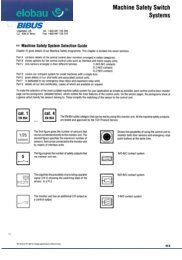
Miniature Shock Absorbers - BIBUS
Miniature Shock Absorbers - BIBUS
Miniature Shock Absorbers - BIBUS

You also want an ePaper? Increase the reach of your titles
YUMPU automatically turns print PDFs into web optimized ePapers that Google loves.
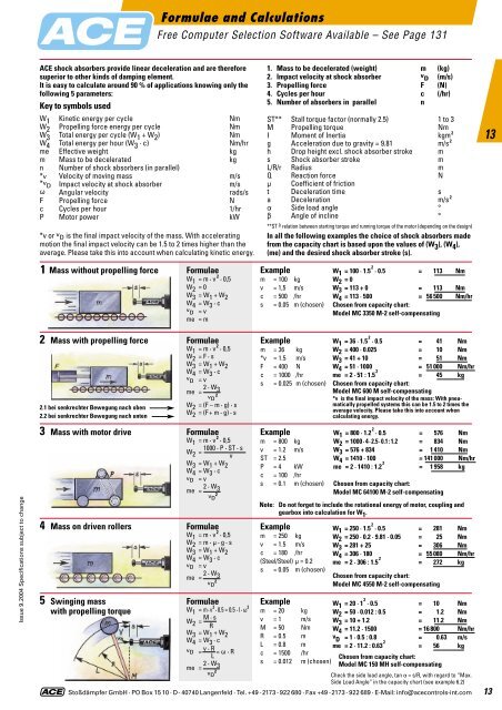
Formulae and CalculationsFree Computer Selection Software Available – See Page 131ACE shock absorbers provide linear deceleration and are thereforesuperior to other kinds of damping element.It is easy to calculate around 90 % of applications knowing only thefollowing 5 parameters:Key to symbols usedW 1 Kinetic energy per cycle NmW 2 Propelling force energy per cycle NmW 3 Total energy per cycle (W 1 + W 2 ) NmW 4 Total energy per hour (W 3 · c) Nm/hrme Effective weight kgm Mass to be decelerated kgn Number of shock absorbers (in parallel)*v Velocity of moving mass m/s*v D Impact velocity at shock absorber m/sv Angular velocity rads/sF Propelling force Nc Cycles per hour 1/hrP Motor power kW*v or v D is the final impact velocity of the mass. With acceleratingmotion the final impact velocity can be 1.5 to 2 times higher than theaverage. Please take this into account when calculating kinetic energy.1. Mass to be decelerated (weight) m (kg)2. Impact velocity at shock absorber v D (m/s)3. Propelling force F (N)4. Cycles per hour c (/hr)5. Number of absorbers in parallel nST** Stall torque factor (normally 2.5) 1 to 3M Propelling torque NmI Moment of Inertia kgm 2g Acceleration due to gravity = 9.81 m/s 2h Drop height excl. shock absorber stroke ms <strong>Shock</strong> absorber stroke mL/R/r Radius mQ Reaction force Nm Coefficient of frictiont Deceleration time sa Deceleration m/s 2a Side load angle °b Angle of incline °**ST =^ relation between starting torque and running torque of the motor (depending on the design)In all the following examples the choice of shock absorbers madefrom the capacity chart is based upon the values of (W 3 ), (W 4 ),(me) and the desired shock absorber stroke (s).131 Mass without propelling forceFormulaeW 1 = m · v 2 · 0,5W 2 = 0W 3 = W 1 + W 2W 4 = W 3 · cv D = vme = mExamplem = 100 kgv = 1,5 m/sc = 500 /hrs = 0.05 m (chosen)W 1 = 100 · 1.5 2 · 0.5 = 113 NmW 2 = 0W 3 = 113 + 0 = 113 NmW 4 = 113 · 500 = 56 500 Nm/hrChosen from capacity chart:Model MC 3350 M-2 self-compensating2 Mass with propelling force2.1 bei senkrechter Bewegung nach oben2.2 bei senkrechter Bewegung nach untenFormulaeW 1 = m · v 2 · 0,5W 2 = F · sW 3 = W 1 + W 2W 4 = W 3 · cv D = vme = 2 · W 3v 2 DW 2 = (F – m · g) · sW 2 = (F + m · g) · sExamplem = 36 kg*v = 1.5 m/sF = 400 Nc = 1000 /hrs = 0.025 m (chosen)W 1 = 36 · 1.5 2 · 0.5 = 41 NmW 2 = 400 · 0.025 = 10 NmW 3 = 41 + 10 = 51 NmW 4 = 51 · 1000 = 51 000 Nm/hrme = 2 · 51 : 1.5 2 = 45 kgChosen from capacity chart:Model MC 600 M self-compensating*v is the final impact velocity of the mass: With pneumaticallypropelled systems this can be 1.5 to 2 times theaverage velocity. Please take this into account whencalculating energy.Issue 9.2004 Specifications subject to change3 Mass with motor drive4 Mass on driven rollers5 Swinging masswith propelling torqueFormulaeW 1 = m · v 2 · 0,51000 · P · ST · sW 2 =vW 3 = W 1 + W 2W 4 = W 3 · cv D = vme = 2 · W 3v 2 DFormulaeW 1 = m · v 2 · 0,5W 2 = m · m · g · sW 3 = W 1 + W 2W 4 = W 3 · cv D = vme = 2 · W 3v 2 DFormulaeW 1 = m · v 2 · 0.5 = 0.5 · I · v 2W 2 = M · sRW 3 = W 1 + W 2W 4 = W 3 · cv D =v · R = v · RLme = 2 · W 3v 2 DExamplem = 800 kgv = 1.2 m/sST = 2.5P = 4 kWc = 100 /hrs = 0.1 m (chosen)Note:Examplem = 20 kgv = 1 m/sM = 50 NmR = 0.5 mL = 0.8 mc = 1500 /hrs = 0.012 m (chosen)W 1 = 800 · 1.2 2 · 0.5 = 576 NmW 2 = 1000 · 4 · 2.5 · 0.1 : 1.2 = 834 NmW 3 = 576 + 834 = 1 410 NmW 4 = 1410 · 100 = 141 000 Nm/hrme = 2 · 1410 : 1.2 2 = 1 958 kgChosen from capacity chart:Model MC 64100 M-2 self-compensatingDo not forget to include the rotational energy of motor, coupling andgearbox into calculation for W 1 .Examplem = 250 kgv = 1.5 m/sc = 180 /hr(Steel/Steel) m = 0.2s = 0.05 m (chosen)W 1 = 250 · 1.5 2 · 0.5 = 281 NmW 2 = 250 · 0.2 · 9.81 · 0.05 = 25 NmW 3 = 281 + 25 = 306 NmW 4 = 306 · 180 = 55 080 Nm/hrme = 2 · 306 : 1.5 2 = 272 kgChosen from capacity chart:Model MC 4550 M-2 self-compensatingW 1 = 20 · 1 2 · 0.5 = 10 NmW 2 = 50 · 0.012 : 0.5 = 1.2 NmW 3 = 10 + 1.2 = 11.2 NmW 4 = 11.2 · 1500 = 16 800 Nm/hrv D = 1 · 0.5 : 0.8 = 0.63 m/sme = 2 · 11.2 : 0.63 2 = 56 kgChosen from capacity chart:Model MC 150 MH self-compensatingCheck the side load angle, tan a = s/R, with regard to “Max.Side Load Angle” in the capacity chart (see example 6.2)Stoßdämpfer GmbH · PO Box 15 10 · D- 40740 Langenfeld · Tel. +49 -2173 - 922 680 · Fax +49 -2173 - 922 689 · E-Mail: info@acecontrols-int.com 13