Arterial Spin Labeling Perfusion MRI Signal Processing Toolbox ...
Arterial Spin Labeling Perfusion MRI Signal Processing Toolbox ...
Arterial Spin Labeling Perfusion MRI Signal Processing Toolbox ...

You also want an ePaper? Increase the reach of your titles
YUMPU automatically turns print PDFs into web optimized ePapers that Google loves.
on accordingly).<br />
Global perfusion difference signals and CBF<br />
values will be saved to a txt file.<br />
All the output files will be saved in the same<br />
directory as the input files.<br />
5.5 Determining ASL data acquisition<br />
parameters<br />
Users should note that ASL acquisition<br />
parameters may be defined differently in different<br />
ASL sequences and it is then necessary to contact<br />
your vendors or the sequence providers about this.<br />
The following text and graphs are based on<br />
Siemens platform. For those who are using GE<br />
product sequence, you will only get a M0 image and<br />
a subtracted perfusion difference image.<br />
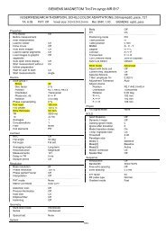
Fig. 5.5.1. Illustration for determining the minimum TR.<br />
Slice timing for 2D: If you open the ASL scan<br />
protocol in the scanner console, you will be able to find a similar interface in the right bottom of the<br />
screen to that shown in Fig. 5.5.1. Click the window after “TR” (as pointed by the blue arrow in Fig. 5.5.1),<br />
you will find a long horizontal colorbar in green at the bottom of the interface. The number under the<br />
colorbar on the left end (pointed by the purple arrow in Fig. 5.5.1) is the minimum TR. Number of slices<br />
can be also found in the same interface in the<br />
second window on the left top corner. Slice timing<br />
can be then calculated using:<br />
(minimum TR – labeling time – post labeling<br />
time)/(number of slices)<br />
For example, in the protocol shown in this<br />
subsection, the slice time will be:<br />
(3230-1406-1500)/14=23.14 ms. Note, this is just an<br />
example, and it should not be treated as a standard<br />
protocol.<br />
<strong>Labeling</strong> time and post labeling time: Case a) in<br />
the UPENN pCASL or the old CASL sequence<br />
distributed by Danny JJ Wang, labeling time is<br />
defined by “Num RF Blocks” (as marked by the blue<br />
Fig. 5.5.2. The pCASL parameter tab.<br />
circle in Fig. 5.5.2). Each RF block lasts for 18500 us,<br />
so the labeling time for 76 RF blocks set in the<br />
protocol shown on the right (Fig. 5.5.2) is 18500usx76=1.406 sec. Post label delay can be directly got<br />
from the window marked with the purple ellipse. Case b) in Siemens product PASL (PICORE) sequence,<br />
you will be able to find "inversion time 1" and "inversion time 2", which is called TI1 and TI2 in the Q2tips<br />
technique developed by Eric Wong. The post labeling delay time to be fed into asl_perf_subtract, the<br />
code for ASL CBF quantification in ASLtbx, should be TI2-TI1; Case c) in GE product sequence<br />
24