Yokogawa GS820 Multi Channel Source Measure Unit
Yokogawa GS820 Multi Channel Source Measure Unit
Yokogawa GS820 Multi Channel Source Measure Unit
- No tags were found...

You also want an ePaper? Increase the reach of your titles
YUMPU automatically turns print PDFs into web optimized ePapers that Google loves.
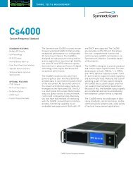
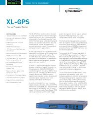
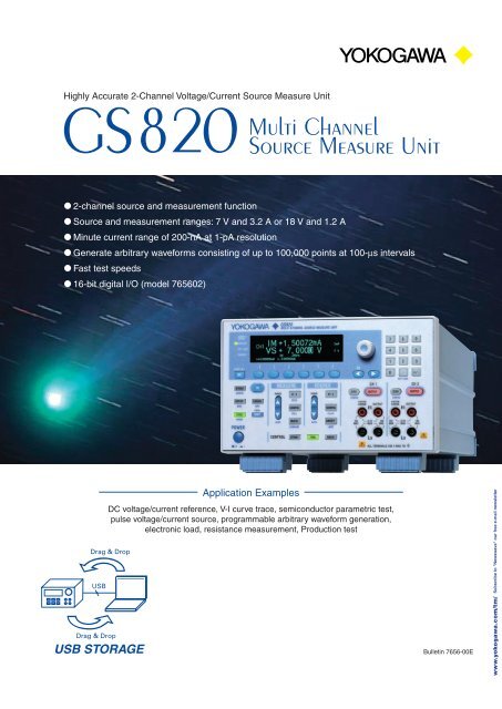
Highly Accurate 2-<strong>Channel</strong> Voltage/Current <strong>Source</strong> <strong>Measure</strong> <strong>Unit</strong><strong>GS820</strong><strong>Multi</strong> <strong>Channel</strong><strong>Source</strong> <strong>Measure</strong> <strong>Unit</strong> 2-channel source and measurement function <strong>Source</strong> and measurement ranges: 7 V and 3.2 A or 18 V and 1.2 A Minute current range of 200-nA at 1-pA resolution Generate arbitrary waveforms consisting of up to 100,000 points at 100-µs intervals Fast test speeds 16-bit digital I/O (model 765602)Drag & DropUSBDrag & DropUSB STORAGEApplication ExamplesDC voltage/current reference, V-I curve trace, semiconductor parametric test,pulse voltage/current source, programmable arbitrary waveform generation,electronic load, resistance measurement, Production testBulletin 7656-00Ewww.yokogawa.com/tm/ Subscribe to "Newswave" our free e-mail newsletter
<strong>Multi</strong> <strong>Channel</strong> <strong>Source</strong> <strong>Measure</strong> <strong>Unit</strong> <strong>GS820</strong>Features<strong>GS820</strong>Highly Accurate 2-<strong>Channel</strong> Voltage/Current <strong>Source</strong> <strong>Measure</strong> <strong>Unit</strong><strong>Multi</strong> <strong>Channel</strong> <strong>Source</strong> <strong>Measure</strong> <strong>Unit</strong>The <strong>GS820</strong> is a highly accurate and highly functional 2-channel programmableDC voltage/current source that incorporates voltage/current generation andmeasurement functions.Features Isolated 2-channel source and measurement function <strong>Source</strong> and measurement ranges: 7 V and 3.2 A or 18V and 1.2 A Minute current ranges with 200-nA or 1-pA resolution Generate arbitrary waveforms consisting of up to100,000 points at 100-µs intervals <strong>Channel</strong> expansion through master-slavesynchronization link Fast test speeds 16-bit digital I/O (model 765602)2-channel display example (256 x 64 dot matrix display)<strong>Source</strong> and <strong>Measure</strong>ment RangeFour-quadrant operation consisting of source operation (currentsource) and sink operation (current sink) is available withranges up to 7 V and 3.2 A or 18 V and 1.2 A.The output and measurement resolutions are 5.5 digits.Current3.2A2Voltage ranges: 200 mV, 2 V, 7 V, and 18 VMaximum output current: ±3. 2 A (at an output voltage of ±7V or less)±1.2 A (at an output voltage of±18 V or less)Current ranges: 200 nA, 2 µA, 20 µA, 200 µA,2 mA, 20 mA, 200 mA, 1 A, and3 AMaximum output voltage: ±18 V (at an output current of ±1.2A or less)±7 V (at an output current of ±3.2A or less)-18VSink<strong>Source</strong>-7V1.2A7V-1.2A-3.2A<strong>Source</strong>Sink18VVoltage
<strong>GS820</strong> Construction and FunctionsFunctionsThe <strong>GS820</strong> is equipped with two analog channels with each channel consisting of a constant voltage source VS, a constantcurrent source IS, a voltmeter VM, and an ammeter IM.The two source measure channels are isolated.<strong>Source</strong> and <strong>Measure</strong>ment Functions: Voltage source and current measurement (VS&IM) Current source and voltage measurement (IS&VM) Voltage source (VS) Current source (IS) Voltmeter (VM) Ammeter (IM) Resistance meter (IS&VM)<strong>Channel</strong> 2<strong>Channel</strong> 1AAmmeterIMVVoltmeter *2VMOutput highSense highDUT *1These functions can be selected for each channel to form anarbitrary combination of functions.ConstantcurrentsourceISConstantvoltagesourceVSSense LowOutput lowAllows voltage sensing of a two-wire system or four-wiresystem by switching between local sense and remote sense.<strong>GS820</strong> construction*1: Device under Test*2: For DUT voltage measurementUsed to measure a four-wire systemCombination of <strong>Source</strong> and <strong>Measure</strong>ment FunctionsThe combination of the source and measurement functions of two channels allows the testing of various DUTs.<strong>GS820</strong><strong>Multi</strong>ple powersource device<strong>Channel</strong> 1<strong>Source</strong>V sourcePower supply 1<strong>Channel</strong> Number1Operation Mode<strong>Source</strong><strong>Channel</strong> 2<strong>Source</strong>V sourcePower supply 22<strong>Source</strong> Application examples:CPU, multi-core MPU, embeddeddevice, hybrid IC, disk drive, andvarious board assemblies<strong>GS820</strong><strong>Channel</strong> 1<strong>Source</strong>V sourceAnalog or digital IC<strong>Channel</strong> Number1Operation Mode<strong>Source</strong><strong>Channel</strong> 2<strong>Measure</strong>V measure2<strong>Measure</strong> Application examples:Op Amp, comparator, logic IC, andvarious board assemblies<strong>GS820</strong><strong>Channel</strong> 1<strong>Source</strong> andmeasureV sourceI measurePower supply IC<strong>Channel</strong> NumberOperation Mode<strong>Channel</strong> 2<strong>Source</strong> andmeasureI source (electronic load)V measure1<strong>Source</strong> and measure2 <strong>Source</strong> and measure Application examples:Three-terminal regulator, DC-DCconverter, bipolar transistor, FET,and various board assemblies3
FunctionsSweep Function 1: Preset SweepThe voltage/current generation block of the <strong>GS820</strong> operates in DC generation mode or pulse generation mode. Each generation mode haspreset operation modes such as continuous output, linear sweep, and log sweep that allow the user to perform sweep operations by settingsimple parameters. The output level can be changed at a minimum of 100-µs intervals *1 in each sweep mode.*1: See *1 minimum program cycle on page 4.<strong>Source</strong> ModeNo Sweep Linear Sweep Log SweepDC sourcePulse sourceSweep Function 2: Arbitrary Waveform Generation of Up to 100,000 Points and Simultaneous Sweeping of Control ParametersIn addition to the preset sweep functions described above, the <strong>GS820</strong> is equipped with a programmable sweep function that allows the userto defi ne the sweep pattern. A user can create or edit arbitrary waveform data (CSV format) of up to 100,000 points using a spreadsheet ortext editor. The <strong>GS820</strong> is also of capable of sweeping the timing and control parameters in addition to the source level. This allows a controlsequence that is synchronized to the waveform generation timing. The sweep program can be changed at a minimum of 100-µs intervals *1 inprogrammable sweep mode.<strong>Source</strong> level Control parameters such as the limit,Timer period measurement range, and comparison value1: See *1 minimum program cycle on page 4.The values do not include the hardware operationtime corresponding to the control parameters.5VTitle lineData linesSL, T1, HL, MR, HC0.0, 2E-3, : , : , :5.0, 3E-3, : , : , :0.0, 4E-3,3.0, 5E-3,1.5, 6E-3,: , :: , :0V2ms3V1.5 V3ms 4ms 5ms 6msSweep program example (CSV format)Control parameters that can be included in a sweep programTitle Symbol Parameter Title Symbol Parameter[CHn.] SF <strong>Source</strong> function T1 Timer 1 period↓ SR <strong>Source</strong> range T2 Timer 2 period↓ SL <strong>Source</strong> level AT Auxiliary trigger generation↓ HL High limit DO Digital output↓ LL Low limit↓ SD <strong>Source</strong> delay↓ PW Pulse width• Write the items you want to defi ne in the title line.↓ PB Pulse base• The items that you can include are source value, measure↓ MS <strong>Measure</strong> ON/OFFvalue, limit value, measurement range, comparison value,period, delay, etc.↓ MF <strong>Measure</strong> function• A channel can be specifi ed for each item (excluding timer,↓ MR <strong>Measure</strong> rangetrigger, and digital output).↓ MD <strong>Measure</strong> delay↓ HC Compare high↓ LC Compare low* [CHn.]: Specify the channel by setting n = 1 or 25
<strong>Multi</strong> <strong>Channel</strong> <strong>Source</strong> <strong>Measure</strong> <strong>Unit</strong> <strong>GS820</strong>FunctionsTest Sequence Editing (Application to Auto Testing Equipment)The <strong>GS820</strong> allows the editing of test sequences suitable for auto testing on the production lines. A user can write program fi le parametersthat are vital to auto testing such as the source value, measured value, high limit for comparison, low limit for comparison, comparisonresult, control bit output, etc. Because the program fi le is in CSV format, a popular spreadsheet application can be used to edit and view theprogram.DUTSwitchMiddle amplifierSwitch<strong>Source</strong>valueInput bufferOutput driver<strong>Measure</strong>dvalue(Switch signal)Digital outputDO2DO1DO0TimestampDigitaloutputDigitalinput<strong>Source</strong>function<strong>Source</strong>value<strong>Measure</strong>mentfunction<strong>Measure</strong>dvalueLow limit forcomparisonHigh limit forcomparisonComparisonresultTM,DO,DI,CH1.SF,CH1.SL,CH1.MF,CH1.ML,CH1.LC,CH1.HC,CH1.CP0.0000,0x0000,0x0000 ,V,+1.00000E+0 ,V,+2.00122E+0 ,+1.95000E+0 ,+2.05000E+0 ,P0.2000,0x0000,0x0000 ,V,+2.00000E+0 ,V,+4.00255E+0 ,+3.90000E+0 ,+4.10000E+0 ,P0.4000,0x0001,0x0000 ,V,+1.00000E+0 ,V,+2.01156E+0 ,+1.95000E+0 ,+2.05000E+0 ,P0.6000,0x0001,0x0000 ,V,+2.00000E+0 ,V,+4.02302E+0 ,+3.90000E+0 ,+4.10000E+0 ,P::::::::::Example of a measurement result fileTest Speed (Improvement in the Takt Time in the Production Line Test)The <strong>GS820</strong> provides fast operation for production line tests. The measured results of test speeds (reference data) are indicated below.<strong>Measure</strong>d values of test speeds (reference data) *1TaskOperationTimeCommand UsedConditionsChange the source level (1 channel) 423 µs :chan1:sour:lev +15.0000 <strong>Measure</strong>ment function OFF, source range fi xed to 18 V.Change the source level (2 channels) 910 µs :chan1:sour:lev +15.0000; :chan2:sour:lev -0.12500 Same as aboveChange the range and source level 978 µs :chan1:sour:rang 18V; lev +15.0000 <strong>Measure</strong>ment function OFFChange the limiter and source level 1,048 µs :chan1:sour:lev +15.0000; prot:lev 200uA <strong>Measure</strong>ment function OFF, source range fi xed to 18 V.Switch the source function 457 µs :chan1:sour:func volt -<strong>Measure</strong> (1 channel) 613 µs :chan1:meas? Integration time 0.001 PLC, auto zero OFF, and external trigger OFF.<strong>Measure</strong> (2 channels simultanesoully) 820 µs :meas? dual Same as aboveChange the source level and measure (1 channel) 985 µs :chan1:sour:lev +15.0000; :chan1:meas? Same as above, source range fi xed to 18 V.Change the source level and measure (2 channels) 1,686 µs :chan1:sour:lev +15.0000; :chan2:sour:lev -0.12500;meas? dual; Same as above*1: <strong>Measure</strong>ment environmentCore 2 Duo processor 2.33 GHz, USB2.0, using LabView6
<strong>Channel</strong> Expansion (Expansion up to 10 <strong>Channel</strong>s Using the Master-Slave Operation)Functions<strong>Multi</strong>ple <strong>GS820</strong>s can be connected as shown below and used as a multi-channel source measure unit. The master-slave feature allowsthe program data of all connected channels to be set and collected by simply accessing the master unit. The master unit distributes thesource data to the slave units or collects and merges the measured data of all slave units. Complete synchronization of all channels canbe achieved by connecting the exclusive trigger signal line.Example of a measurement result filePC<strong>Channel</strong> 1CH1.SF , CH1.SL , CH1.MF , CH1.ML , CH1.LC , CH1.HC , CH1.CPV , +1.00000E+0 , V , +2.00122E+0 , +1.95000E+0 , +2.05000E+0 , P<strong>Channel</strong> 2CH2.SF , CH2.SL , CH2.MF , CH2.ML , CH2.LC , CH2.HC , CH2.CPV , +1.00000E+0 , V , +2.01156E+0 , +1.95000E+0 , +2.05000E+0 , PDrag &drop<strong>Channel</strong> 3CH3.SF , CH3.SL , CH3.MF , CH3.ML , CH3.LC , CH3.HC , CH3.CPV , +1.00000E+0 , V , +2.01156E+0 , +1.95000E+0 , +2.05000E+0 , PUSB-PC connectionGP-IB, RS232, orEthernetA,B,CBMaster unit: A Slave unit: B Slave unit: CC<strong>Channel</strong>1<strong>Channel</strong>2<strong>Channel</strong>3<strong>Channel</strong>4<strong>Channel</strong>9<strong>Channel</strong>10OUTINOUTINTRIGTRIGEthernetEthernetEthernetBC← <strong>Measure</strong>d data Control commands and source data →HUB← <strong>Measure</strong>d data Control commands and source data →Zero Generation Function of Voltage and Current (Fast Load Disconnection without Chattering)The zero generation function of the <strong>GS820</strong> generates zero voltage or current as well as controls the current/voltage limiter to limit the loadcurrent. The <strong>GS820</strong> stops applying the voltage or supplying the current to the load in the zero generation state allowing the DUT to bedisconnected with the output relay turned ON. This function avoids the problems of chattering and contact life of the output relay and reducesthe time for turning ON/OFF the output.Zero generation of voltage Low impedance: The current limiter is set to the specifiedvalue. High impedance: The current limiter is set to 10 nA.Zero generation of current Low impedance: The voltage limiter is set to 1 mV. High impedance: The voltage limiter is set to the specifiedvalue.Output relay:Output relay:Constantly ONConstantly ON DUT DUT7
<strong>Multi</strong> <strong>Channel</strong> <strong>Source</strong> <strong>Measure</strong> <strong>Unit</strong> <strong>GS820</strong>Applications<strong>Measure</strong>ment of the Static Characteristics of Three-Terminal Semiconductor Devices (Transistors, FETs, etc.)The <strong>GS820</strong> can measure drain current ID by applying gate-source voltage VGS from channel 1 and drain-source voltage VDS from channel 2.Connection example for measurements<strong>Channel</strong> 1V sourceVGSGDSID<strong>Channel</strong> 2 AV sourceI measurementVDSFeatures Voltage application and current measurement usingtwo synchronized channels Minute current measurement at 200-nA range and1-pA resolution Curve trace function using voltage/current sweep Output measured data in CSV format Easy access to the internal USB memory No dedicated software required<strong>GS820</strong><strong>Source</strong> <strong>Measure</strong> <strong>Unit</strong>Drag & drop<strong>Measure</strong>ment data fi leCH1.Vgs(V) CH2.Id(A)0.00E+00 8.87E-03-2.00E-02 8.46E-03-4.00E-02 8.05E-03-6.00E-02 7.65E-03-8.00E-02 7.26E-03-1.00E-01 6.87E-03-1.20E-01 6.49E-03-1.40E-01 6.12E-03-1.60E-01 5.76E-03(data edited in the spreadsheet)GraphDrain current (A)ID-VGS1.0E-028.0E-036.0E-034.0E-032.0E-030.0E+00-1.0 -0.8 -0.6 -0.4 -0.2 0.0Gate-source voltage VGS (V)Timing Tests at Power-On of <strong>Multi</strong>ple Power SuppliesThe <strong>GS820</strong> can generate different supply voltages from the two channels to drive a multiple power source device. The transient changes inthe source voltage can be programmed by entering values in a general-purpose spreadsheet.Timing at Power-On (<strong>Source</strong> Data)Features Synchronized output of twopower supplies Maximum output current of 3.2A x 2 channels Easy voltage programming No dedicated software requiredDL9000 Series DigitalOscilloscope<strong>Source</strong> data file1.4-V powersupply (V)0.000.010.020.030.040.050.060.070.080.090.100.110.12Supply voltage (V)Drag & dropStartup waveform of multiple power supplies3.532.521.510.500 0.1 0.2 0.3 0.4 0.5 0.6 0.7Time (s)1.4V power(V) 3.3V power(V)Timing at Power-On (<strong>Source</strong> Data)Drag & drop<strong>Source</strong> data file3.3-V powersupply (V)0.000.020.040.060.080.100.120.140.160.180.200.220.24Signalanalysis3.3 V (I/O voltage)1.4 V (internal voltage)<strong>Channel</strong> 1V source<strong>Channel</strong> 2V source<strong>GS820</strong><strong>Source</strong> <strong>Measure</strong> <strong>Unit</strong>Microprocessor8
<strong>Measure</strong>ment of I/O Characteristics of Semiconductor DevicesApplicationsThe <strong>GS820</strong> is used to apply voltage Vi to the gate input of a logic IC from channel 1 and measure gate output voltage Vo on channel 2. Thesource and measure channels allow the I/O characteristics of the gate to be measured.Input voltage ViApplyOutput voltage Vo<strong>Measure</strong>Features Voltage application and voltage measurementusing two synchronized channels Curve trace function using voltage sweep Output measured data in CSV format Easy access to the internal USB memory No dedicated software required<strong>Channel</strong> 1V sourceV<strong>Channel</strong> 2V measurementI/O characteristics of a NAND gate<strong>GS820</strong><strong>Source</strong> <strong>Measure</strong> <strong>Unit</strong>Drag & drop<strong>Measure</strong>ment data fi leCH1.Vi (V) CH2.Vo (V)0.00E+00 5.01E+002.00E-01 5.01E+004.00E-01 5.01E+006.00E-01 5.01E+008.00E-01 5.01E+001.00E+00 5.01E+001.20E+00 5.01E+001.40E+00 5.01E+001.60E+00 5.01E+001.80E+00 5.01E+00GraphOutput voltage Vo (V)6.05.04.03.02.01.00.00.0 1.0 2.0 3.0 4.0 5.0 6.0-1.0Input voltage Vi (V)(data edited in the spreadsheet)Power Conversion Effi ciency <strong>Measure</strong>ment of Power Supply ICsThe <strong>GS820</strong> can measure the power conversion effi ciency of a three-terminal regulator or a DC-DC converter. A channel for supplying poweris connected to the primary circuit and another channel for consuming power is connected to the secondary circuit. Then, the load currentis swept to vary the consumed power and supplied power. The power conversion effi ciency is determined from the ratio of the consumedpower to the supplied power.Power supplyPower consumption<strong>Measure</strong>ment result example (data edited in the spreadsheet)Voltage and current inthe primary circuitVoltage and current inthe secondary circuitEfficiency =Consumed power in the secondary circuit/supplied power in the primary circuit<strong>Channel</strong> 1V sourceI measurementA<strong>Channel</strong> 2I sourceV measurement<strong>GS820</strong> <strong>Source</strong> <strong>Measure</strong> <strong>Unit</strong>Features Power supply operation and power consumption (load)operation Generate and measure up to 7 V and 3.2 A or 18 Vand 1.2 A Data collection and calculation using general-purposespreadsheets No dedicated software requiredDrag & dropVTime(s) <strong>Source</strong>(V) <strong>Measure</strong>(A) <strong>Source</strong>(A) <strong>Measure</strong>(V) Input(W) Output(W) Efficiency0 7.00 0.002617 0.00 4.95495 1.83E-02 0.00E+00 0.00%0.55 7.00 0.102457 -0.10 4.94771 7.17E-01 4.95E-01 68.99%1.1 7.00 0.202470 -0.20 4.94113 1.42E+00 9.88E-01 69.73%1.65 7.00 0.302443 -0.30 4.93466 2.12E+00 1.48E+00 69.93%2.2 7.00 0.402436 -0.40 4.92822 2.82E+00 1.97E+00 69.98%2.75 7.00 0.502437 -0.50 4.92177 3.52E+00 2.46E+00 69.97%3.3 7.00 0.602380 -0.60 4.91529 4.22E+00 2.95E+00 69.94%3.85 7.00 0.702407 -0.70 4.90882 4.92E+00 3.44E+00 69.89%4.4 7.00 0.802434 -0.80 4.90221 5.62E+00 3.92E+00 69.82%4.95 7.00 0.902451 -0.90 4.89524 6.32E+00 4.41E+00 69.74%5.5 7.00 1.002370 -1.00 4.88563 7.02E+00 4.89E+00 69.63%Output voltage (V)5.004.954.904.854.804.75Power conversion efficiency of a voltage regulator4.704.65Output Voltage4.60Efficiency4.554.5060%0.0 0.2 0.4 0.6 0.8 1.0Output current (A)Graph80%70%Power conversion efficiency* More application examples are introduced at our Website.URL: http://www.yokogawa.com/tm/gmi/gs610/tm-gs610_10.htm9
<strong>Multi</strong> <strong>Channel</strong> <strong>Source</strong> <strong>Measure</strong> <strong>Unit</strong> <strong>GS820</strong>Specifi cations<strong>Source</strong> SectionDC Voltage <strong>Source</strong>Range<strong>Source</strong>RangeResolutionMax.LoadCurrentAccuracy (One Year)±(% of setting + V)Temperature Coeffi cient±(% of setting + V)/°C200 mV ±200.000 mV 1 µV ±3.2 A 0.02 + 250 µV 0.003 + 35µV2 V ±2.00000 V 10 µV ±3.2 A 0.02 + 400 µV 0.003 + 60µV7 V ± 7.0000 V 100 µV ±3.2 A 0.02 + 2 mV 0.003 + 300µV18 V ±18.0000 V 100 µV ±1.2 A 0.02 + 2 mV 0.003 + 300µVOutput resistance (for four-wire system remote sensing)200 mV, 2 V range: (Shunt resistance/40000) Ω or less7 V, 18 V range: (Shunt resistance/5000) Ω or less* Shunt resistance: See “DC Current <strong>Measure</strong>ment”One year accuracy for 23±5 °C.Add the temperature coeffi cient for 5 to 18 °Cand 28 to 40°C.DC Current <strong>Source</strong>Range <strong>Source</strong> Range ResolutionMax.LoadVoltageAccuracy (One Year)±(% of setting + A)Temperature Coeffi cient±(% of setting + A)/°C200nA ±200.000nA 1pA ±18V 0.06 + 3nA 500pA2µA ±2.00000µA 10pA ±18V 0.04 + 3nA 500pA20µA ±20.0000µA 100pA ±18V 0.03 + 3nA 0.0045 + 450pA200µA ±200.000µA 1nA ±18V 0.03 + 30nA 0.0045 + 4.5nA2mA ±2.00000 mA 10nA ±18 V 0.03 + 250 nA 0.0045 + 37.5 nA20mA ±20.0000 mA 100nA ±18 V 0.03 + 2.5µA 0.0045 + 375 nA200mA ±200.000 mA 1µA ±18 V 0.03 + 25µA 0.0045 + 3.75 µA1A ±1.20000 A 10µA ±18 V 0.05 + 900µA 0.0075 + 135 µA3A ±3.20000 A 10 µA ±7 V 0.05 + 1.5 mA 0.0075 + 225 µAOne year accuracy for 23±5 °C.Add the temperature coeffi cient for 5 to 18 °Cand 28 to 40 °C.Output resistance(Shunt resistance x 50000) Ω or more* Shunt resistance: See “DC Current <strong>Measure</strong>ment”One year accuracy for 23±5 °C.Add the temperature coeffi cient for 5 to 18 °C and 28 to40 °C.Current Limiter|Setting| *1 Range Resolution Min. Setting10.000 nA to 200.000 nA 200nA 1pA 10nA0.20001 µA to 2.00000 µA 2µA 10pA 10nA2.00001 µA to 20.0000 µA 20 µA 100pA 100nA20.0001 µA to 200.000 µA 200 µA 1nA 1µA200.001 µA to 2.00000 mA 2 mA 10nA 10µA2.00001 mA to 20.0000 mA 20 mA 100nA 100µA20.0001 mA to 200.000 mA 200 mA 1µA 1mA0.20001 A to 1.20000 A 1A 10µA 10mA1.20001 A to 3.20000 A 3A 10µA 10mAResponse Time (Typical)200 mV range 250usCurrent <strong>Source</strong> 2 V range 50us7 V, 18 V range 100us200 nA range 250ms2 µA range 25msVoltage <strong>Source</strong> 20 µA range 2.5ms200 µA range 250us2 mA to 3 A range 80usIn normal mode.The time for the output to reach within 0.1% of the fi nal value after theoutput starts changing.Pure resistive load. The limiter setting is at the full scale of the range.<strong>Source</strong> voltage or current is at the maximum value of the range.Voltage Limiter|Setting| *1 Range Resolution Min. Setting1.000 mV to 200.000 mV 200 mV 1 µV 1 mV0.20001 V to 2.00000 V 2 V 10 µV 1 mV2.00001 V to 7.0000 V 7 V 100 µV 5 mV7.0001 V to 18.0000 V 18 V 100 µV 5 mV*1: Larger of the two values |high limit value| or |low limit value|when tracking is OFFLC LoadCurrent <strong>Source</strong>/<strong>Measure</strong>ment/ Normal ModeStable ModeLimiter RangeMax. C load Max. L load Max. C load Max. L load200 nA to 2 mA 0.01 µF20 mA 0.1 µF200 mA 1 µF10 µH 100 µF 1 mH2 A, 3 A 10 µFOutput Noise (Typical)20 mVp-pFor DC to 20 MHz, 2-V voltage source range, and 1-A currentlimiter range<strong>Measure</strong>ment SectionDC Voltage <strong>Measure</strong>mentRange <strong>Measure</strong>mentRange Resolution Accuracy±(% of reading + V) Temperature Coeffi cient±(% of reading + V)/°C200 mV ±210.000 mV 1 µV 0.015 + 200 µV (250 µV) {300 µV} [500 µV] 0.0025 + 30 µV ( 40 µV) { 45 µV} [ 60 µV]2 V ±2.10000 V 10 µV 0.015 + 200 µV (400 µV) { 1 mV} [ 5 mV] 0.0025 + 30 µV ( 60 µV) {200 µV} [800 µV]7 V ±7.1000 V 100 µV 0.015 + 2 mV ( 4 mV) { 10 mV} [ 50 mV] 0.0025 + 300 µV (600 µV) { 2 mV} [ 8 mV]18 V ±18.0000 V 100 µV 0.015 + 2 mV ( 4 mV) { 10 mV} [ 50 mV] 0.0025 + 300 µV (600 µV) { 2 mV} [ 8 mV]DC Current <strong>Measure</strong>mentRange <strong>Measure</strong>mentRange Resolution Shuntresistance Accuracy±(% of reading + A) Temperature Coeffi cient±(% of reading + A)/°C200 nA ±210.000 nA 1 pA 1 M Ω 0.05 + 3 nA ( 3 nA) { 3 nA} [ 4 nA] 500 pA (500 pA) {500 pA} [600 pA]2 µA ±2.10000 µA 10 pA 1 M Ω 0.025 + 3 nA ( 3 nA) { 4 nA} [ 6 nA] 500 pA (500 pA) {500 pA} [600 pA]20 µA ±21.0000 µA 100 pA 100 k Ω 0.025 + 4 nA ( 6 nA) { 10 nA} [ 50 nA] 0.004 + 600 pA (900 pA) { 1.5 nA} [ 8 nA]200 µA ±210.000 µA 1 nA 10 k Ω 0.02 + 40 nA ( 60 nA) {100 nA} [500 nA] 0.003 + 6 nA ( 9 nA) { 15 nA} [ 80 nA]2 mA ±2.10000 mA 10 nA 1 k Ω 0.02 + 400 nA (600 nA) { 1 µA} [ 5 µA] 0.003 + 60 nA ( 90 nA) {150 nA} [800 nA]20 mA ±21.0000 mA 100 nA 100 Ω 0.02 + 4 µA ( 6 µA) { 10 µA} [ 50 µA] 0.003 + 600 nA (900 nA) { 1.5 µA} [ 8 µA]200 mA ±210.000 mA 1 µA 10 Ω 0.02 + 70 µA (100 µA) {150 µA} [500 µA] 0.003 + 10 µA ( 15 µA) { 20 µA} [ 80 µA]1A ±1.30000 A 10 µA 1 Ω 0.03 + 700 µA ( 1 mA) { 2 mA} [ 6 mA] 0.0045 + 100 µA (150 µA) {300 µA} [900 µA]3A ±3.20000 A 10 µA 1 Ω 0.05 + 1 mA (1.5 mA) { 2 mA} [ 6 mA] 0.0075 + 150 µA (200 µA) {300 µA} [900 µA]10One year accuracy for 23±5 °C.Add the temperature coeffi cient for 5 to 18°C and 28 to 40 °C.Values inside parentheses are for 0.1 PLC ? integration time < 1 PLC. Values inside braces are for 0.01 PLC ? integration time < 0.1 PLC.Values inside brackets are for 0.001 PLC ? integration time < 0.01 PLC.
Specifi cationsFunctions <strong>Source</strong>Function:Voltage or currentMode: DC or pulse (pulse width: 50 µs to 3,600 s)Sweep mode:Linear, logarithmic, or program (up to 100,000 steps)Trigger source: External or internal timers 1 and 2 (period: 100 µs to 3600 s)Sweep start source: External or internal timers 1 and 2 (period: 100 µs to 3600 s)<strong>Source</strong> delay:15 µs to 3600 sResponse characteristics: Normal or stable <strong>Measure</strong>mentFunction:Voltage, current, auto, voltmeter mode, ammetermode, or resistance meter modeIntegration time: 0.001 to 25 PLC (Power Line Cycle)Trigger source: External or internal timers 1 and 2 (period: 100 µs to 3600 s)<strong>Measure</strong> delay: 0 µs to 3600 s<strong>Measure</strong>ment data storage: Up to 100000 data pointsAverage: Moving average (average count: 2 to 256)Voltage sense:Two-wire system or four-wire systemAuto zero:<strong>Measure</strong> the internal zero reference everymeasurement and correct the measured valueNULL computation: Computes the difference with respect to the currentmeasuredvalue or user-defi ned valueUser-defi ned computation: Computes user-defi ned equations in real-timeOperators:+[addition], -[subtraction], *[multiplication], /[division], ^[exponentiation], % [mod], | [logic OR], & [logic AND], ! [negation],< >= == != [comparison], = [substitution],Functions:ABS() [absolute value], SQRT() [square root], LN(), LOG()[logarithm], SIN(), COS(), TAN() [trigonometric functions],ASIN(), ACOS(), ATAN() [inverse trigonometric functions],SINH(), COSH(), TANH() [hyperbolic functions], RAND() (randomnumber generation), EDGE() [logic change extraction],TRUNC(), FLOOR() [rounding to an integer], ISINF() [infi nityjudgment], ISNAN [not-a-number judgment]Conditional statement: IF-THEN-ELSEExternal I/O BNC I/OConnector type BNC connectorI/O levelTTLI/O logic format Negative logic, falling edgeMinimum pulse width 10 µs Digital I/OConnector type: D-Sub 15-pin (765601 standard model)Half-pitch 50-pin (765602 digital I/O installed model)I/O level:TTLMinimum pulse width: 10 µsSignal NameSignal Name<strong>Channel</strong> 1 Comparison endDO12 *comparisonComparison result low DO13 *Digital outputComparison result IN DO14 *result output Comparison result high DO15 *<strong>Channel</strong> 2 Comparison endDI0comparisonComparison result lowDI1Comparison result IN DI2 *result output Comparison result high DI3 *Interlock input DI4 *DO0 DI5 *DO1 DI6 *DO2 * DI7 *DO3 * Diginal inputDI8 *DO4 * DI9 *Digital outputDO5 * DI10 *DO6 * DI11 *DO7 * DI12 *DO8 * DI13 *DO9 * DI14 *DO10 * DI15 *DO11 ** DO2 to 15, DI2 to 15Available on the digital I/O installed model (765602) I/O for Synchronized OperationConnector type:RJ-11 connectorBNC connector (select the signal to be assigned tothe input and output, separately)I/O level:TTLMinimum pulse width: 10 µsI/O signal for synchronized operationPin No. Sync Input Connector Sync Output Connector1 Output relay control input Output relay control output2 Sweep start input Sweep start output3 Trigger input Trigger output4 GND GND5 Auxiliary trigger input Auxiliary trigger output6 Zero source control input Zero source control outputRJ-11 connectorCompatible cable: 758930Communication Interface GPIBElectrical and mechanical specifi cations: Conforms to IEEE St'd 488-1987Functional specifi cations: SH1, AH1, T6, L4, SR1, RL1, PP0, DC1, DT1, C0Protocol: Conforms to IEEE St'd 488.2-1987Address: 0 to 30 RS232Connector type:Electrical specifi cations:Connection format:Transmission mode:Synchronization mode:Baud rate:D-Sub 9-pinConforms to EIA RS232Point-to-pointFull-duplexStart-stop synchronization9600, 14400, 19200, 38400, 57600, 115200 bps USB interfaceNumber of ports: 1Connector type:Type B connector (receptacle)Electrical and mechanical specifi cations: Conforms to USB Rev. 2.0Protocol:Mass storage class, USB-TMC EthernetNumber of Ethernet ports: 1Connector type:RJ-45 connectorElectrical and mechanical specifi cations: Conforms to IEEE 802.3Transmission system: 100BASE-TX/10BASE-TData rate:100 Mbps or 10 MbpsProtocol:VXI-11 server, HTTP server, FTP server, DHCP client,and command socketGeneral Specifi cationsDisplay:256 64 dot VFDRated supply voltage: 100 to 120 VAC or 200 to 240 VACRated supply frequency: 50/60 HzPower consumption: Approx. 250 VAWarm-up time:At least 60 minutesOperating temperature and humidity range:5 °C to 40 °C and 20% to 80%RH (no condensation)Storage temperature and humidity range:-15 °C to 60 °C and 20% to 80%RH (no condensation)Max. common-mode voltage: Between the case and each terminal ±250 VpkMaximum allowable input voltage: Between high sense and low sense ±18 VpkBetween high output and low output ±18 VpkBetween high sense and high output ±0.5 VpkBetween low sense and low output ±0.5 VpkBetween each terminal of CH1 and each terminal of CH2 ±250 VpkExternal dimensions: Approx. 213 (W) 132 (H) 450 (D) mm (excludingprojections)Weight:Approx. 8 kg External Dimensions<strong>Unit</strong>: mmD-Sub 15-pin(model 765601)Half-pitch 50-pin(model 765602)11
Order In for ma tion & OthersMODEL and SUFFIX CodeModel Suffi x Code Notes765601<strong>GS820</strong> <strong>Multi</strong> <strong>Channel</strong> <strong>Source</strong> <strong>Measure</strong> <strong>Unit</strong> StandardModel765602<strong>GS820</strong> <strong>Multi</strong> <strong>Channel</strong> <strong>Source</strong> <strong>Measure</strong> <strong>Unit</strong> Digital I/OInstalled Model-D UL/CSA standard-F VDE standardPower cord -R AS standard-Q BS standard-H GB standardNote:The test certifi cate and calibration certifi cate can be requested only at the time of the order. Please don't forget to requestthem as they cannot be issued after the product has been delivered.Standard AccessoriesPower cord, rubber feet (4 pieces), measurement leads 758933 (2 sets), smallalligator clip adapters 758922 (2 sets), user’s manuals (1 set) External I/O connectorOptional AccessoriesModel Product Specif ications758933 <strong>Measure</strong>ment leadSafety terminal cable 1 m and 2 leads (red andblack) in a set758917 <strong>Measure</strong>ment leadSaf ety terminal cable 0.75 m and 2 leads (red andblack) in a set758919 Banana plug set ø 4-mm plug/ø 4-mm socket adapterSmall alligator clip Saf ety terminal-alligator clip adapter and 2758922adapteradapters (red and black) in a setLarge alligator clip758929adapter758921 Fork terminal adapterSaf ety terminal-to-alligator clip adapter and 2adapters (red and black) in a setSaf ety terminal-to-f ork terminal adapter and 2adapters (red and black) in a set758924 Conversion adapter BNC-to-binding post adapter366924 BNC cable BNC-BNC cable 1 m366925 BNC cable BNC-BNC cable 2 m758923 Safety terminal adapterSpring clamp ty pe 2 adapters (red and black) in aset758931 Safety terminal adapter Screw-in ty pe 2 adapters (red and black) in a set758960 Synchronizationoperation cableRJ11 6-pin 1 mRack Mount KitsModel Product Specifi cations751533-E3 Rack mount kit For EIA single mount751533-J3 Rack mount kit For JIS single mount751534-E3 Rack mount kit For EIA dual mount751534-J3 Rack mount kit For JIS dual mount758933 <strong>Measure</strong>ment lead2 pieces (red and black) in 1 set, length: 1.00 mUsed in combination with the 701959, 758921, 758922, or 758929.Rating: 1000 V CAT III/19 A758917 <strong>Measure</strong>ment lead2 pieces (red and black) in 1 set, length: 0.75 mUsed in combination with the 701959, 758921, 758922, or 758929.Rating: 1000 V CAT II/32 ACore 2 Duo is a registered trademark of Intel Corporation.LabView is a registered trademark of National Instruments.Ethernet is a registered trademark of XEROX Corporation.758921 Fork terminal adapterSafety terminal (banana female)-to-4 mm fork terminal adapter, 2pieces (red and black) in 1 set Rating: 1000 V CAT IIConnected to the 758933, 758917, or 701901.758919 Banana plug setφ 4-mm plug/ φ 4-mm socket adapterRating: 30 VAC to 60 VDC 30 A Related ProductsGS610<strong>Source</strong> <strong>Measure</strong> <strong>Unit</strong>Wide-range source andmeasurement function<strong>Source</strong> and measurement range:±110 V and ±3.2 A758922 Small alligator clip adapterSafety terminal (banana female)-to-alligator clip adapter, 2 pieces(red and black) in 1 setRating: 300 V CAT II Connected to the 758933, 758917, or 701901.758929 Large alligator clip adapterSafety terminal (banana female)-to-alligator clip adapter, 2 pieces(red and black) in 1 setRating: 1000 V CAT II Connected to the 758933, 758917, or 701901.7651Programmable DC <strong>Source</strong>Highly accurate, highly stable,and low noiseOutput range: ±30 V and±120 mA758924 Conversion adapterSafety terminal (banana female)-to-BNC (male) adapterConnected to the 758933, 758917, or 701901.366924/366925 BNC cable366924: Length 1 m366925: Length 2 mNoteDue to the nature of the product, it is possible for the user to comein contact with metal parts and receive electric shock.Exercise caution when using the product.758923 Safety terminal adapter set 758931 Safety terminal adapter setSpring clamp type (banana male) 2 pieces in 1 setEasy attachment/detachment of the cable.*1 Screw-in type (banana male)2 pieces in 1 set*1Comes with a B9317WD 1.5-mm hexagonal wrench for fixing thecable in place.*1 Wire diameter of cables that can connect to the adapter758923 Core wire diameter: 2.5 mm or less, covering diameter: 5.0 mm or less758931 Core wire diameter: 1.8 mm or less, covering diameter: 3.9 mm or lessYOKOGAWA ELECTRIC CORPORATIONCommunication & <strong>Measure</strong>ment Business Headquarters /Phone: (81)-422-52-6768, Fax: (81)-422-52-6624E-mail: tm@cs.jp.yokogawa.comYOKOGAWA CORPORATION OF AMERICA Phone: (1)-770-253-7000, Fax: (1)-770-251-6427YOKOGAWA EUROPE B.V. Phone: (31)-33-4641858, Fax: (31)-33-4641859YOKOGAWA ENGINEERING ASIA PTE. LTD. Phone: (65)-62419933, Fax: (65)-62412606Subject to change without notice.[Ed : 01/b] Copyright ©2007Printed in Japan, 707(KP)MS-16E