ALIGNMENT PROCEDURE - CB Tricks
ALIGNMENT PROCEDURE - CB Tricks
ALIGNMENT PROCEDURE - CB Tricks
- No tags were found...
You also want an ePaper? Increase the reach of your titles
YUMPU automatically turns print PDFs into web optimized ePapers that Google loves.
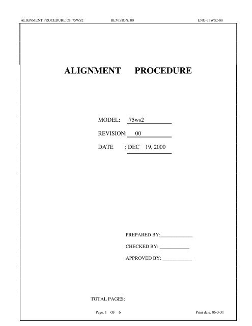
<strong>ALIGNMENT</strong> <strong>PROCEDURE</strong> OF 75WS2 REVISION: 00 ENG-75WS2-08<strong>ALIGNMENT</strong><strong>PROCEDURE</strong>MODEL:75ws2REVISION: 00DATE : DEC 19, 2000PREPARED BY:_____________CHECKED BY: ____________APPROVED BY: ____________TOTAL PAGES:Page: 1 OF 6 Print date: 06-3-31
<strong>ALIGNMENT</strong> <strong>PROCEDURE</strong> OF 75WS2 REVISION: 00 ENG-75WS2-081.8. TEST EQUIPMENT SETUP AS BELOW:A. TX test equipment setup:SpectrumAnalyzerPowerSupplyModulation Wattmeter 75WS2MeterD.U.T.Oscilloscope Frequency Audio Gen.CounterDistortionMeterACVoltmeterB. RX test equipment setup:SINAD Meter RF Signal PowerGeneratorSupplyDistortion 8 ohm 75WS2Meter loading D.U.T.OscilloscopeNote: D.U.T. = device under testPage: 3 OF 6 Print date: 06-3-31
<strong>ALIGNMENT</strong> <strong>PROCEDURE</strong> OF 75WS2 REVISION: 00 ENG-75WS2-082.3 <strong>CB</strong> Receiver AlignmentTEST ITEM TEST CONDITION & <strong>PROCEDURE</strong> PURPOSE1. Audio output level 1. <strong>CB</strong> RX mode.2. ST to OFF3. Output of signal generator thru 0.01uFto TP3.4. RF Gen. set 10.7MHz, Fmod= 1KHz,AM= 30%, level: 1mV.5. Set Volume control to middle position.6. Set Squelch to minimum.2. RX sensitivity 1. Set normal band CH19.2. Output of signal generator to antennainput terminal.3. RF Gen. set 27.185MHz, fm: 1kHz,1. Adjust L8 and L23 formaximum audio output &minimum distortion at thedistortion meter.( Distortionless than 5% )2. Set volume control tomaximum position, audiopower output shall be morethan 0.35 Watts.1. Adjust L5, L6 and L10for more than 10dB S/Nratio.2. Repeat as needed.3. SQUELCH control( Tight Squelch )AM= 30%, RF level: 1µV.1. Set normal band CH19.2.Output of signal generator to the antennainput terminal.3. RF Gen. set 27.185 MHz , Fmod= 1KHz,AM= 30%, RF level: 2000 µV.4. Rotate the Squelch control to fullyclockwise positionCheck CH1 and CH40.1. Slowly turn VR5 to aposition that the audiooutput waveform at theoscilloscope just appearsfrom no output.2. Must open at 4000uV.3. Must not open at 800uV.4. Signal meter display 1. Set normal band CH19.2. Output of signal generator to antennainput terminal.RF Gen. set 27.185MHz, no modulation,RF level: 100 µV.1. Adjust VR1 for “9”displayed on the signalmeter of LCD .2. Increase RF level by 30dB.The signal meter should be5. Sound Tracker( ST must be on )a) S/Nb) Audio Gain1. Set normal band CH19.2. RF Gen. set 27.185MHz,30% modulation3. S/N @ RF level 1.0uV@ RF level 1000uV4. Audio Gain @ 100uV 50% Mod.displayed at “+30” position.1. S/N: 1.0uV ≥ 15dB.1000uV ≥ 50dB.2. ST audio output change2-8dB from OFF to ON.Page: 5 OF 6 Print date: 06-3-31
<strong>ALIGNMENT</strong> <strong>PROCEDURE</strong> OF 75WS2 REVISION: 00 ENG-75WS2-082.4 <strong>CB</strong> Transmitter AlignmentTEST ITEM TEST CONDITION & <strong>PROCEDURE</strong> PURPOSE1. TP4 Alignment 1. Channel set normal band CH 19.2. Set TX mode.Connect the TP4 thru a 10pF capacitor tothe oscilloscope.1. Adjust L24,L21formaximum RF outputwaveform on the scope.(Freq. = 27.185MHz)2. Repeat as needed.2. TX Carrier output power 1. Channel set normal band CH 19.2. Set TX mode.3. Connect an RF wattmeter to the antennasocket.1. AdjustL14 for 4.0 wattsRF output power.2. Check TX CH1 and CH40should meet D.T.S.3.TX Carrier frequency 1. Channel set CH 19.detector.2. Set TX mode.4. TX Signal meter 1. Connect an RF wattmeter to the antennasocket.2. No modulation.3. Set TX output power for 3watts.5. MAXIMUM Modulation 1. Set TX mode.(AMC control)Output of AF generator to MIC jack, @1000Hz, 25 mV . ST set off.6. TX 2 nd harmonics 1. Connect an RF wattmeter to the antennasocket.7. Occupied band width, 1. Set TX High power mode( OBW )2. Set modulation frequency 2500 Hz.3.6mv.Turn vc1 for 27.185MHz ±300Hz at the frequencycounter.Adjust VR6 for “3”displayed at the TX signalstrength of the LCD.1. Adjust VR2 for 88%modulation.2. Distortion less than 8.0%at 80% modulation.3. Check CH1,CH40.Reading 2 nd harmonics mustless than -60dB at spectrumanalyzer.The frequency spectrum of theharmonics should be at least 2dB better than the limits of theFCC specification.Page: 6 OF 6 Print date: 06-3-31


