Read/Download - SKB
Read/Download - SKB
Read/Download - SKB
- No tags were found...

Create successful ePaper yourself
Turn your PDF publications into a flip-book with our unique Google optimized e-Paper software.
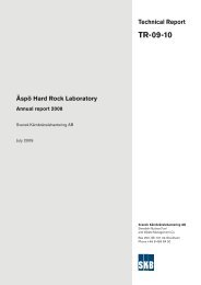
Compressed air inWater inWater out~ 10 mOuter support casingInner supportcasingWater and drillcuttings outAir outAir in~10 -100 mLowerpressureHigherpressure~ 2 mDown to theboreholebottomFigure 3‐4. Air-lift pumping during core drilling of a telescopic borehole. Schematic representation,where the drilling depths are only approximate. The air and instrumentation hoses are secured to theouter support casing. The compressed air raises the flushing water and drill cuttings from the hole.Return water flows between the borehole wall and the drilling pipe string and then through holes inthe support casing before being transported up to the surface.The air-lift pumping equipment in KFM06C consisted of the following main components,see Figure 3-4:• Compressor, 12 bars/10 m³/min.• 100 m outer support casing, 98/89 mm diameter.• 100.5 m inner support casing, 84/77 mm diameter.• PEM hose: 20 bars, 22 mm diameter, 400 m.• PEM hose: 20 bars, 28 mm diameter, 200 m.• Expansion vessel (= discharge head).• Pressure sensor, 10 bars, instrumentation and data‐logging unit.• Electrical supply cubicle, at least 16 A.• Ejector tube.18