Read/Download - SKB
Read/Download - SKB
Read/Download - SKB
- No tags were found...
Create successful ePaper yourself
Turn your PDF publications into a flip-book with our unique Google optimized e-Paper software.
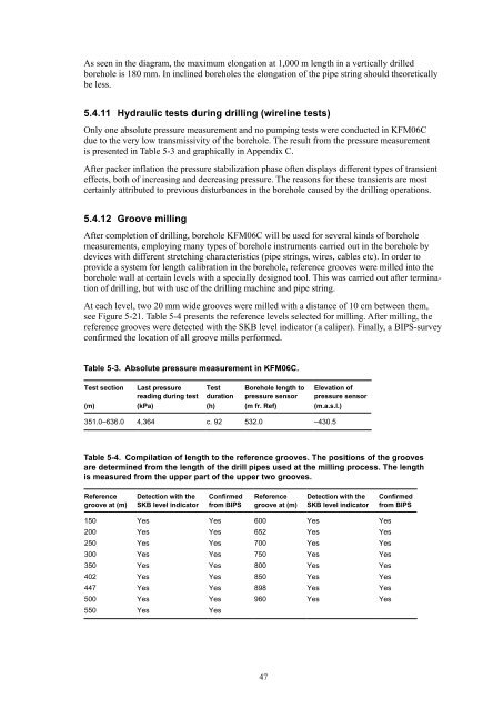
As seen in the diagram, the maximum elongation at 1,000 m length in a vertically drilledborehole is 180 mm. In inclined boreholes the elongation of the pipe string should theoreticallybe less.5.4.11 Hydraulic tests during drilling (wireline tests)Only one absolute pressure measurement and no pumping tests were conducted in KFM06Cdue to the very low transmissivity of the borehole. The result from the pressure measurementis presented in Table 5-3 and graphically in Appendix C.After packer inflation the pressure stabilization phase often displays different types of transienteffects, both of increasing and decreasing pressure. The reasons for these transients are mostcertainly attributed to previous disturbances in the borehole caused by the drilling operations.5.4.12 Groove millingAfter completion of drilling, borehole KFM06C will be used for several kinds of boreholemeasurements, employing many types of borehole instruments carried out in the borehole bydevices with different stretching characteristics (pipe strings, wires, cables etc). In order toprovide a system for length calibration in the borehole, reference grooves were milled into theborehole wall at certain levels with a specially designed tool. This was carried out after terminationof drilling, but with use of the drilling machine and pipe string.At each level, two 20 mm wide grooves were milled with a distance of 10 cm between them,see Figure 5-21. Table 5-4 presents the reference levels selected for milling. After milling, thereference grooves were detected with the <strong>SKB</strong> level indicator (a caliper). Finally, a BIPS-surveyconfirmed the location of all groove mills performed.Table 5-3. Absolute pressure measurement in KFM06C.Test sectionLast pressurereading during testTestdurationBorehole length topressure sensorElevation ofpressure sensor(m) (kPa) (h) (m fr. Ref) (m.a.s.l.)351.0–636.0 4,364 c. 92 532.0 –430.5Table 5-4. Compilation of length to the reference grooves. The positions of the groovesare determined from the length of the drill pipes used at the milling process. The lengthis measured from the upper part of the upper two grooves.Referencegroove at (m)Detection with the<strong>SKB</strong> level indicatorConfirmedfrom BIPSReferencegroove at (m)Detection with the<strong>SKB</strong> level indicatorConfirmedfrom BIPS150 Yes Yes 600 Yes Yes200 Yes Yes 652 Yes Yes250 Yes Yes 700 Yes Yes300 Yes Yes 750 Yes Yes350 Yes Yes 800 Yes Yes402 Yes Yes 850 Yes Yes447 Yes Yes 898 Yes Yes500 Yes Yes 960 Yes Yes550 Yes Yes47


