238-45085-00B - Bradford White
238-45085-00B - Bradford White
238-45085-00B - Bradford White
- No tags were found...

Create successful ePaper yourself
Turn your PDF publications into a flip-book with our unique Google optimized e-Paper software.
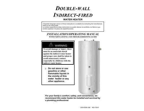
DOUBLE-WALLINDIRECT-FIREDWATER HEATERA Spanish language version of these instructions is available by contacting the manufacturerlisted on the rating plate.La version espanola de estas instruccions se puede obtener al escribirle a la fábrica cuyonombre aparece in la placa de especificaciones.INSTALLATION/OPERATING MANUALWITH PARTS LISTING AND TROUBLESHOOTING GUIDEWARNINGTo avoid damage or injury, theremust be no materials storedagainst the indirect water heaterand proper care shall be taken toavoid unnecessary contact(especially by children) with theindirect water heater.Do not store or usegasoline or otherflammable liquids inthe vicinity of thiswater heater or anyother appliance.For your family’s comfort, safety, and convenience, werecommend this water heater be installed and serviced bya plumbing professional.<strong>238</strong>-<strong>45085</strong>-<strong>00B</strong> REV 05/07
CONGRATULATIONS!You have just purchased one of the finest water heaterson the market today!This installation, operation, and instruction manual willexplain in detail the installation and maintenance of yournew Indirect water heater. We strongly recommend thatyou contact a plumbing professional for the installation ofthis water heater.We require that you carefully read this manual, as well asthe enclosed warranty, and refer to it if questions arise.If you have any specific questions concerning yourwarranty, please consult the plumbing professional fromwhom your water heater was purchased. For yourrecords we recommend that you write the model, serialnumber and installation date of your water heater in theback of this manual.This manual should be kept with the water heater.We’re committed to providing you with the finest waterheater made.2
CAUTIONThe maximum boiler water supply temperature to the indirectheat exchanger must not exceed 240°F (115°C).NOTICEInsulation blankets are not required for this water heater. Thiswater heater meets or exceeds the ASHRAE/IES 90.1b standardswith respect to insulation and standby loss requirements.TABLE OF CONTENTSI- IMPORTANT INFORMATION…………….….. 4II- SPECIFICATIONS………………………………. 8III- GENERAL INFORMATION……………………. 11IV- PRE-INSTALLATION…………………………… 14V- WATER CONNECTIONS……………………….. 18VI- ELECTRICAL CONNECTIONS……………….. 23VII- OPERATING INSTRUCTIONS………………… 26VIII- MAINTENANCE…………………………………. 29IX- TROUBLESHOOTING GUIDE………………… 32X- PARTS LIST……………………………………… 34XI- NOTES ……………………………………………. 363
SECTION IIMPORTANT INFORMATION-READ CAREFULLY-The equipment must be installed in accordance with thoseinstallation regulations required in the area where the installationis to be made. These regulations must be carefully followed inall cases. Authorities having jurisdiction shall be consultedbefore installations are made.All wiring on water heaters installed in the USA must be inaccordance with the National Electrical Code and/or localregulations; or in Canada, installed in accordance with theCanadian Electrical Code and/or local regulations.The following terms are used throughout this manual to bringattention to the presence of hazards of various risk levels, or toimportant information concerning product life.DANGERIndicates an imminentlyhazardous situation, which,if not avoided, will result indeath, serious injury, orsubstantial propertydamage.CAUTIONIndicates a potentiallyhazardous situation, which,if not avoided, may resultin moderate, or minorinjury or property damage.WARNINGIndicates a potentiallyhazardous situation, which,if not avoided, could resultin death, serious injury, orsubstantial propertydamage.NOTICEIndicates specialinstructions on installation,operation or maintenance,which are important butnot related to personalinjury hazards.4
Important Info continued-DANGERDO NOT store or use gasoline or other flammable,combustible, or corrosive vapors and/or liquids in the vicinityof this or any other appliance.IF YOU SMELL GAS: DO NOT try to light any appliance. DO NOT touch any electric switch; do not use anytelephone in your building. Immediately call your gas supplier from a telephone inanother building. Follow the gas supplier’s instructions. If you cannot reach your gas supplier, call the firedepartmentDO NOT OPERATE THE APPLIANCE UNTIL THELEAKAGE IS CORRECTED!Liquefied petroleum gas/propane gas is heavier than air andwill remain at floor level if there is a leak. Basements, crawlspaces, closets, and areas below ground level will serve aspockets for accumulation of leaking gas.This water heater is supplied with an adjustable thermostat tocontrol water temperature. Hot water temperatures requiredfor automatic dishwasher and laundry use can cause scaldburns resulting in serious personal injury and/or death. Thetemperature at which injury occurs varies with the person’sage and the time of exposure. The slower response time ofdisabled persons increases the hazards to them. NEVER allowsmall children to use a hot water tap or to draw their own bathwater. NEVER leave a child or disabled person unattended ina bathtub or shower.To comply with NSF requirements this water heater is to be:a) Sealed to the floor with sealant, in a smooth and easilycleanable way, orb) Installed with an optional leg kit that includes legsand/or extensions that provide a minimum clearance of6” beneath the water heater.5
Important Info continued-WARNINGInstallation is not complete unless a properly sized/capacitypressure and temperature relief valve is installed into the sideof the water heater. See the General Information section of thismanual for details.This water heater contains very hot water under high pressure.Do not unscrew any pipe fittings or attempt to disconnect anycomponents of this water heater without positively assuring thewater is cool and has no pressure. Always wear protectiveclothing and equipment when installing, starting up, orservicing this water heater to prevent scald injuries. Do notrely on the pressure and temperature gauges to determine thetemperature and pressure of the water heater. This waterheater contains components that become very hot. Do nottouch any components unless they are cool.Improper installation, adjustments, alteration, service ormaintenance can cause property damage, personal injury orloss of life. Failure to follow all instructions in the proper ordercan cause personal injury or death. Read and understand allinstructions, including all those contained in componentmanufacturer’s manuals, which are provided with theappliance before installing, starting-up, operating, maintaining,or servicing this appliance. Keep this manual and literature inlegible condition and posted near the appliance for reference byowner and service technician.This water heater requires regular maintenance and service tooperate safely. Follow the instructions contained in thismanual.Installation, maintenance, and service must be performed onlyby an experienced, skilled, and knowledgeable installer orservice agency.6
Important Info continued-WARNINGIt is the responsibility of the installing contractor to see that allcontrols are correctly installed and are operating properlywhen the installation is complete.DO NOT operate the water heater with jumpered or absentcontrols or safety devices.DO NOT tamper with or alter the water heater and/or controls.DO NOT operate the water heater if any external part has beenunder water. Immediately call a qualified service technician toinspect the appliance and to replace any part of the controlsystem that was under water.This water heater is suitable for installation on combustibleflooring. DO NOT install this water heater on carpeting.DO NOT operate this water heater without first being certain itis filled with water.Flammable items, pressurized containers, or any other potentialfire hazardous articles must never be placed on or adjacent tothe heater. Containers of flammable gases should not be storedor used in the same room with this water heater.Hydrogen gas can be produced in an operating water heaterthat has not had water drawn from the tank for a long period oftime (generally two weeks or more). Hydrogen gas is extremelyflammable. To prevent the possibility of injury under theseconditions, we recommend that the water faucet be opened forseveral minutes at the kitchen sink before you use any electricalappliance that is connected to the hot water system. Ifhydrogen is present, there will be unusual sounds such as airescaping through the pipes as hot water begins to flow. Do notsmoke or have open flame near the faucet at the time it is open.7
Specifications continued-Table 2: Water Heater CapacitiesTankMODEL Capacity(Gal)CoilVolume(Gal)DryWeight(Lbs)WetWeight(Lbs)40-Gal. 38 2.5 170 47050-Gal. 46 2.5 180 54765-Gal. 60 2.5 196 69580-Gal. 75 2.5 224 848Table 3: Certified I=B=R Water Heater RatingsContinuous StandbyFirst Hour Draw Heat LossMODELRating Rating Rating(Gal/Hr) (Gal/Hr) (°F/Hr)MinimumOutput ofHeat Source(BTU/Hr)MinimumHeat SourceFlow Rate(Gal/Min)40-Gal 123 98 1.1 65,000 8.050-Gal 133 98 0.9 65,000 8.065-Gal 148 98 0.7 65,000 8.080-Gal 158 98 0.6 65,000 8.0NOTE: These certified ratings were obtained with a heat sourceoutput and flow rate as specified in Table 3 and a 180°F boiler watersupply temperature. Other results will be obtained under differentconditions.Table 4: Water Heater PerformanceMODELMaximum FirstHour Rating(Gal/Hr) @140 °F 115 °FContinuousDraw Rating(Gal/Min) @140 °F 115 °FApproximateBoiler OutputNeeded ForRatings(BTU/hr)40-Gal. 190 285 2.6 4.2 140,00050-Gal. 200 295 2.6 4.2 140,00065-Gal. 210 305 2.6 4.2 140,00080-Gal. 225 320 2.6 4.2 140,000NOTE: Based on 200 °F boiler water temperature and 50 °F potablewater inlet temperature.9
Specifications continued-Table 5: Water Heater PerformanceMODELHot WaterAvailability(Minutes)Coil HeatTransfer Area(Sq Ft)Pressure Drop atRated HeatSource Flow Rate(Feet of Head)40-Gal. 6.8 14.2 2.450-Gal. 8.6 14.2 2.465-Gal. 10.8 14.2 2.480-Gal. 13.5 14.2 2.4NOTICEIf the boiler takes longer to heat up from a cold startthan the water availability as noted above, hot watershortage may occur.Hot water availability is based on drawing 80% of theheated tank volume at 4 gallons per minute flow rate.The maximum heat transfer through the coil (heatinput) of the water heater at 240°F boiler water supplytemperature and 210°F potable water temperature is23,500 Btu/hr. Potable water temperature is limited tobelow 210 °F and nominal water-containing capacityis below 120 gallons for all indirect-fired models.Accordingly, per Part HLW-101.2, Section IV of theASME Boiler and Pressure Vessel Code, all indirectfiredproducts listed are exempted from compliancewith the code.10
SECTION IIIGENERAL INFORMATIONFEATURESThis water heater contains the following features:HEAT EXCHANGER -- The heat exchanger (coil) has 3/4” NPTfemale fittings.Water heaters with a double-wall heat exchanger meet the UniformPlumbing Code for installation in all potable water systems. The doublewallconstruction provides protection in the event that either the potableor hydronic heat exchanger barrier is penetrated. The fluid will movealong in integrated leak path within the heat exchanger, leaving theexchanger through a weep hole located in the fittings. If a confirmedleak occurs, contact the plumbing professional who installed the waterheater or the manufacturer, listed on the rating plate, for additionalguidance.This indirect-fired water heater is appropriate for all potable heatingsystems, even where a single-wall exchanger is not approved by theauthority having jurisdiction.ADJUSTABLE THERMOSTAT – The temperature may be adjustedfrom approximately 80°F to approximately160°F. The thermostat isfactory set at 120°F. It is recommended that lower temperatures be usedto avoid the risk of scalding. Refer to the “Warnings” and the section onSCALDING in “Section VII – Operating Instructions.” It is furtherrecommended, in all cases, that the water temperature be set for thelowest temperature that satisfies your hot water needs. This will alsoprovide the most energy efficient operation of the water heater andminimizes scale formation.Setting the water heater temperature at 120°F will reduce the risk ofscalds. Some states require settings to specific lower temperatures.11
General Info continued-TEMPERATURE AND PRESSURE RELIEF VALVEWARNINGKeep clear of the combination temperature and pressure reliefvalve discharge line outlet. The discharge may be hot enough tocause scald injury. The water is under pressure and may splash.For protection against excessive temperatures and pressure, installtemperature and pressure protective equipment required by localcodes, but not less than a combination temperature and pressurerelief valve certified by a nationally recognized testing laboratorythat maintains periodic inspection of production of listed equipmentor materials as meeting the requirements of the Standard for ReliefValves and Automatic Gas Shutoff Devices for Hot Water SupplySystems, ANSI Z21.22 and the Standard CAN1-4.4 Temperature,Pressure, Temperature and Pressure Relief Valves and VacuumRelief Valves. The combination temperature and pressure reliefvalve must be marked with a maximum set pressure not to exceedthe maximum working pressure of the water heater. Thecombination temperature and pressure relief valve must also havean hourly rated temperature steam BTU discharge capacity not lessthan the hourly rating of the water heater. The suppliedcombination temperature and pressure relief valve, when properlyinstalled and unrestricted, will discharge the maximum inputproduced by a 240°F (115°C) boiler supply temperature. A lowerboiler supply temperature will reduce the input required to bedischarged in the event of excessive potable water temperatures.Install the combination temperature and pressure relief valve intothe opening provided and marked for this purpose on the waterheater.Some models may already be equipped or supplied with atemperature and pressure relief valve. Verify that the combinationtemperature and pressure relief valve complies with local codes. Ifthe temperature and pressure relief valve does not comply withlocal codes, replace it with one that does.12
General Info continued-WARNINGInstall a discharge line so that water discharged from thetemperature and pressure relief valve will exit within six (6) inchesabove, or any distance below, the structural floor and cannotcontact any live electrical part. The discharge line is to be installedto allow for complete drainage of both the temperature and pressurerelief valve and the discharge line. The discharge opening must notbe subjected to blockage or freezing. DO NOT thread, plug, or capthe discharge line. It is recommended that a minimum clearance offour (4) inches be provided on the side of the water heater forservicing and maintenance of the combination temperature andpressure relief valveDo not place a valve between the combination temperature andpressure relief valve and the tank!SACRIFICIAL ANODES — Two sacrificial anode rods have beeninstalled in the tank head to extend tank life. The anode rods should beinspected annually to determine the amount of sacrificial decay andreplaced when necessary to prolong tank life. Water conditions in yourarea will influence the time interval for inspection and replacement of theanode rod. The use of a water softener may increase the speed of anodeconsumption. More frequent inspection of the anode is needed whenusing softened (or phosphate treated) water. Contact the plumbingprofessional who installed the water heater or the manufacturer, listed onthe rating plate, for anode replacement information.13
SECTION IVPRE-INSTALLATIONUNPACKINGINSPECT SHIPMENT carefully for any signs of damage. Ifdamage is noted, do not install the product. Contact the shipper ormanufacturer. All equipment is carefully manufactured, inspected,and packed. Our responsibility ceases upon delivery of thepackaged water heater to the carrier in good condition.NOTE: Any claims for damage or shortage in shipment must befiled immediately against the carrier by the consignee.This water heater MUST be installed indoors out of the wind andweather.IMPORTANT DECISIONS REQUIRED BEFOREINSTALLATIONSIZING1. Boiler DOE Heating Capacity – The indirect-fired waterheater will provide the rated performance only if used inconjunction with a heat source with a DOE heatingcapacity (Heat Output) at least as much as the minimumnoted in Table 3. If the heat source has less capacity, theoutput of the tank will be reduced. To determine theapproximate reduction in output from the tank use thefollowing formula:New Rating = (maximum continuous draw rating) xActual Output of Heat SourceMinimum Output of Heat SourceFor example, what would the continuous draw rating be if a 50-gallon indirect-fired water heater were installed with a heatsource having a DOE heating capacity of 55,000 BTU/h?Answer:New Rating= 98 gal/hr x (55,000 BTU/h)/(65,000 BTU/h)= 98 gal/hr x 0.846 = 83 gal/hr14
Pre-installation continued-NOTICEIncreasing the boiler DOE heating capacity above thevalues listed in Table 3 will not increase the rating ofthe water heater.2. Circulator Sizing – Refer to Table 5 for the correspondingpressure drop through the coil for the given model. Calculatethe pressure drop of all straight pipe and fittings on the supplyand return of the water heater at the selected flow rate. Addthe piping/fitting pressure drop to the pressure drop throughthe water heater coil.Select a circulator that will provide an appropriate flow rate atthe combined pressure drop.SYSTEM ZONE CONTROLThe indirect-fired water heater must be installed as a zoneseparate from the space heating system. The domestic hotwater zone’s piping and circulator must be sized for aminimum flow rate with all zones in use and a maximum flowrate with only the water heater in use. For this reason, thepreferred method of zone control is with circulators.1. Circulators – With space heating zones usingcirculators, the indirect-fired heater should be addedas an additional zone with a circulator.2. Zone Valves – Select a valve with a low-pressuredrop to assure adequate flow through the water heater.3. Hybrid – The space heating zone can be zoned usingzone valves and the indirect-fired heater zoned with acirculator.15
Pre-installation continued-DOMESTIC HOT WATER PRIORITYTwo options are available, Priority and Non-Priority.1. Priority – Demand for space heating is interrupted orpostponed until the domestic hot water demand is satisfied.This option provides maximum delivery of domestic hotwater. Priority is recommended when:a) Boiler net output is 100,000 Btu per hour or less, orb) When boiler output required to satisfy domestic hotwater demand is at least 50% of the boiler outputrequired to satisfy space heating demand, orc) When an interruption in space heating can be toleratedduring a long domestic hot water draw.2. Non-Priority – Boiler output is divided between spaceheating and domestic hot water heating. Delivery ofdomestic hot water can be reduced during simultaneousspace and domestic hot water heating operations,depending on such factors as boiler output, boiler oversizing,number of space heating zones calling for heat, andthe ratio of domestic hot water load to space heating load.Component LocationCAUTIONThis water heater must be located in an area where leakage of thetank, water line connections, or the temperature and pressure reliefvalve will not result in damage to the area adjacent to the waterheater or to lower floors of the structure. When such locationscannot be avoided, a suitable drain pan must be installed under thewater heater. The drain pan depth must be suitable for draining andcollecting water. The drain pan can be purchased from yourplumbing professional. The drain pan must be piped to an adequatedrain. The piping must be at least ¾ inch in diameter and pitchedfor proper drainage.16
Pre-installation continued-Clearance from Combustible MaterialsTop Sides Front RearNon-PipingSide0” 0” 0” 0”Table 6 – Combustible Material ClearancesRecommended Service ClearancesFront(Thermostat)RearT & P ReliefValve Side4” 16” 0” 4”Table 7 – Service ClearancesCAUTIONDo not drop water heater. Do not bump water heater jacket againstfloor.Appliance Location1. Boiler Location – Locate the indirect-fired water heater asclose to the boiler as practical.2. Fixture Locations – For fastest delivery of hot water, placethe indirect-fired water heater close to points of use.Additional Recommended Components1. Shut-off Valves – Allows isolation of water heater fromdomestic water system and/or boiler system during service.2. Unions – Allows water heater movement during service ifadequate clearance cannot be provided.3. Thermal Expansion Tank – If the water heater is installed ina closed water supply system, such as one having a back-flowpreventer in the cold water line, provide thermal expansioncontrol. Contact the water supplier or local plumbing inspectorfor additional information.WARNINGDo not plug the inlet and outlet tappings of tankless heater leftinstalled in the boiler.17
Pre-installation continued-MOVE THE WATER HEATER TO A PERMANENTPOSITION BY SLIDING OR WALKING.NOTICEFor California installation this water heater must be braced,anchored, or strapped to avoid falling or moving during anearthquake. See instructions for correct installation procedures.Instructions may be obtained from California Office of the StateArchitect, 400 P Street, Sacramento, CA 95814.SECTION VWATER CONNECTIONSWARNINGFAILURE TO INSTALL AND MAINTAIN A NEW, LISTEDTEMPERATURE AND PRESSURE RELIEF VALVE WILLRELEASE THE MANUFACTURER FROM ANY CLAIMWHICH MIGHT RESULT FROM EXCESSIVETEMPERATURE AND PRESSURES.Hydrogen gas can be produced in an operating water heater thathas not had water drawn from the tank for a long period of time.HYDROGEN GAS IS EXTREMELY FLAMMABLE. To preventthe possibility of injury under these conditions, we recommend thehot water faucet be opened for several minutes at the kitchen sinkbefore you use any electrical appliance that is connected to the hotwater system. If hydrogen is present, there will be an unusualsound such as air escaping through the pipes as hot water begins toflow. Do not smoke or have open flame near the faucet at the timeit is open.Keep clear of the temperature and pressure relief valve dischargeline outlet. The discharge may be hot enough to cause scald injury.The water is under pressure and may splash.18
Water Connections continued-CAUTIONIf sweat fittings are to be used, DO NOT apply heat to the nippleson top of the water heater. Sweat the tubing to the adapter beforefitting the adapter to the water connections. It is imperative thatheat is not applied to the nipples containing a plastic liner.INSTALL TEMPERATURE AND PRESSURE RELIEFVALVE (if not factory installed)WARNINGTemperature and pressure relief valve discharge piping must bepiped near the floor to eliminate potential of severe burns. Donot pipe in any area where freezing could occur. Do not installany shut-off valves, plugs or caps to the temperature andpressure relief valve or piping.INSTRUCTIONS FOR POTABLE CONNECTIONS1. BEFORE PROCEEDING WITH THE INSTALLATION,CLOSE THE MAIN WATER SUPPLY VALVE. Aftershutting off the main water supply, open a faucet to relieve thewater line pressure to prevent any water from leaking out ofthe pipes while making the water connections to the waterheater. After the pressure has been relieved, close the faucet.The COLD water inlet and HOT water outlet are identified onthe top of the water heater. Make the proper plumbingconnections between the water heater and the plumbing systemto the house. Install a shut-off valve in the cold water supplyline.2. If this water heater is installed in a closed water supply system,such as one having a back-flow preventer in the cold watersupply, provisions must be made to control thermal expansion.DO NOT operate this water heater in a closed system withoutprovisions for controlling thermal expansion. Warranties donot cover damages from thermal expansions such as pressurebulges and/or deformities. A properly sized expansion tankwill alleviate most problems. Your water supplier or local19
Water Connections continued-plumbing inspector should be contacted on how to control thissituation.3. After installation of the water lines, open the main watersupply valve and fill the water heater. While the water heateris filling, open several hot water faucets to allow air to escapefrom the water system. When steady streams of water flowthrough the faucets, close them and check all waterconnections for possible leaks.4. NEVER OPERATE THE WATER HEATER WITHOUTFIRST BEING CERTAIN THAT IT IS FILLED WITHWATER.INSTRUCTIONS FOR BOILER CONNECTIONSThe indirect-fired heater connection labeled “To Boiler Return”should be piped to the boiler return piping as close to the boiler aspossible and especially after any flow control or check valves inthe space heating return piping. The use of a union and a shut-offvalve is recommended. The use of a flow control or check valve isrequired to prevent back flow through the water heater duringoperation of the space heating system. Pipe and fittings betweenthe boiler and indirect-fired water heater should be ¾” diameter orlarger.CAUTIONMaximum boiler water supply temperature to the indirectheat exchanger must not exceed 240°F (116°C).CONNECT WATER BOILER SUPPLY PIPING1. For a space heating system that utilizes ZONE VALVES, referto Figure 2. The indirect-fired water heater connection labeled“FROM BOILER SUPPLY” should be piped to the boilersupply piping. Mount the circulator making sure the flow arrowpoints toward the water heater. The use of shut-off valves andunions are recommended for future service convenience. Theuse of an air separator and vent is recommended to eliminate airin the system. Pipe and fittings between the boiler and indirectfiredwater heater must be ¾” diameter or larger.20
Water Connections continued-Figure 2 - Water Boiler Piping with Zone Valves2. For a space heating system that utilizes CIRCULATORS, referto Figure 3. The indirect-fired water heater connection labeled“FROM BOILER SUPPLY” should be piped to the boilersupply piping. Mount the circulator making sure the flow arrowpoints toward the water heater. The use of shut-off valves andunions are recommended for future service convenience. Theuse of an air separator and vent is recommended to eliminate airin the system. Pipe and fittings between the boiler and indirectfiredwater heater must be ¾” diameter or larger.Figure 3 - Water Boiler Piping with Circulators21
Water Connections continued-CONNECT STEAM BOILER SUPPLY PIPINGFigure 4 represents a typical steam boiler connection diagram.Refer to the boiler installation manual or contact the boilermanufacturer for an appropriate piping diagram. The use of aunion, shut-off valves, and a drain valve is recommended forfuture service convenience. The use of an in-line “Y”-stylestrainer is required to prevent accumulation of sludge in the waterheater’s coil.Figure 4 – Typical Steam Boiler Connections (connections availablebelow the water line)NOTICETypical steam boiler without connections available below the water lineis not recommended due to insufficient water temperature, especiallyduring warmer months when the space heating system is notoperational. Boiler water temperature at the bottom of a steam boilercan be 50°F lower than the boiler’s water temperature limit settingduring such periods.FILL BOILER SYSTEM1. On new boiler installations, do not purge the boiler or spaceheating system through the water heater. During any boiler orspace heating system flushing, cleaning, or purging, the waterheater should be isolated to avoid possible attack on the carbonsteel coil by chemical additives.2. Purge air from boiler/water heater piping.3. Check system for leaks. Repair as necessary.22
SECTION VIELECTRICAL CONNECTIONSInstall electric wiring in accordance with National Electric Code orthe Canadian Electrical Code and local regulations. See theboiler’s installation manual for wiring diagrams.DANGERPositively assure all electrical connections are unpowered beforeattempting installation or service of electrical components orconnections of the water heater or building. Lock out allelectrical boxes with padlock once power is turned off.WARNINGWhen installed, the water heater must be electrically grounded inaccordance with local codes or, in the absence of local codes,with the National Electrical Code, ANSI/NFPA 70, and /or theCSA C22.1 Electric Code.Failure to properly wire electrical connections to the water heatermay result in serious physical harm.Electrical power may be from more than one source. Make sureall power is off before attempting any electrical work.The thermostat incorporates a manual reset temperature-limitingdevice. Please refer to the TROUBLESHOOTING GUIDE sectionfor manual reset operation.The thermostat incorporates a manual adjustable temperatureindicator to change the potable water temperature. Please refer toWATER TEMPERATURE ADJUSTMENT in the OPERATINGINSTRUCTIONS section for proper instruction in adjusting watertemperature. Turn off all power related to the boiler and heatingsystem before proceeding with the electrical connections.23
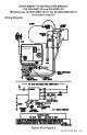
Electrical Connections continued-The thermostat switch is a single pole, single throw device. Thefield connections shall be used as a control for one leg of theelectrical circuit. The thermostat switch can be used in the range of24 to 480 volts with a maximum current load of 15 amps. Any andall wiring shall be sized and installed to satisfy the voltage andamperage used. All wiring shall be done in accordance with allapplicable local and state codes.GENERAL INSTALLATIONSIf a circulator is used to control the heating fluid flow from thewater heater to the boiler, a zone relay is required between thewater heater thermostat and the boiler. Connect the white wire onthe water heater to one leg of the circulator. The second leg of thecirculator is to be connected to “L2” (120V neutral). Connect thewhite wire on the water heater to one leg of the zone relay. Thesecond leg of the zone relay is to be connected to “L2” (120Vneutral). The contact side of the zone relay is to be connected tothe boiler operating control (see figure 5). Connect the black wireon the water heater to “L1” (120V hot). These connections enablewater heater thermostat to control the circulator, the zone relay,and the boiler operating control.Figure 5 – Electrical Connection with Circulator24
Electrical Connections continued-If a zone valve to used to control the heating fluid flow from theboiler to the water heater, a zone step-down transformer isrequired between the water heater thermostat and the zone valve.Connect the white wire on the water heater to one leg of thetransformer primary side. The second leg of the primary side is tobe connected to “L2” (120V neutral). The secondary side of thetransformer is to be connected to the zone valve coil. The contactside of the zone valve is to be connected to the boiler operatingcontrol. Connect the black wire on the water heater to “L1” (120Vhot) (see figure 6). These connections enable the water heaterthermostat to control the zone valve and the boiler operatingcontrol.Figure 6 – Electrical Connection with Zone ValveOther installations may require slightly different wiringarrangements. In all cases it is important to remember that thethermostat on the water heater only controls one leg of the system.25
SECTION VIIOPERATING INSTRUCTIONSWARNINGWater heaters are heat-producing appliances. To avoid damageor injury there must be no materials stored against the waterheater, and proper care must be taken to avoid unnecessarycontact (especially by children) with the water heater.UNDER NO CIRCUMSTANCES SHALL FLAMMABLEMATERIALS, SUCH AS GASOLINE OR PAINT THINNERBE USED OR STORED IN THE VICINITY OF THE WATERHEATER OR IN ANY LOCATION FROM WHICH FUMESCOULD REACH THE WATER HEATER.Installation or service of this water heater requires abilityequivalent to that of a licensed tradesman in the fieldinvolved. Plumbing and electrical work are required.SYSTEM START-UPFollow boiler installation instructions to place boiler in operation.SEQUENCE OF OPERATIONS1. Thermostat senses stored water temperature drops belowdesired setting.a. Domestic hot water priority only: Normally closed contactsopen to interrupt space heating.2. Thermostat satisfied.a. Thermostat contacts open, turning off domestic hot watercirculator and de-energizing relay.b. Normally open contacts open, stopping boiler operation.c. Domestic hot water priority only: Normally closed contactsclose, returning boiler control to space heating.26
Operating Instructions continued-WATER TEMPERATURE ADJUSTMENTWARNINGSCALDINGThis water heater can deliver scalding temperature water at anyfaucet in the system. Be careful whenever using hot water toavoid scalding injury. By setting the thermostat on this waterheater to obtain an increased water temperature, you may createthe potential for scald injury. To protect against injury, youshould install an ASSE approved mixing valve (a device to limitthe temperature of water to protect against scald injury viamixing hot and cold water supply) in the water system. This valvewill reduce point of discharge temperature in branch supply lines.Such valves are available from the manufacturer of this waterheater or a local plumbing supplier. Please consult with aplumbing professional.Table 8 details the approximate relationship of watertemperature and time with regard to scald injury and may beused as a guide in determining the safest water temperature foryour applications.• •• •• •••••••••• • • •••••••••••• ••Figure 7 - Scald WarningAPPROXIMATETIME/TEMPERATURERELATIONSHIPS IN SCALDS120°F More than 5 minutes125°F 1 ½ to 2 minutes130°F About 30 seconds135°F About 10 seconds140°F Less than 5 seconds145°F Less than 3 seconds150°F About 1 ½ seconds155°F About 1 secondTable 8 – Scald Relationships27
Operating Instructions continued-CAUTIONBefore adjusting the thermostat, turn off all power supplied to theindirect-fired water heater.The potable water temperature can be changed by adjusting thethermostat. Before any work is done on the water heater,disconnect all power to the water heater and heat source (boiler)by opening the switch(s) at the main electrical circuit breaker orfuse box. Remove the access panel and fold the insulationoutward away from the control. Adjust the thermostat dial using ascrewdriver until the minimum acceptable temperature is achieved.The thermostat has been factory preset to 120°F (49°C).Remember that lower temperature settings are more energyefficient. Rotate the temperature dial clockwise to increasewater temperature. Rotate the thermostat dial counter-clockwiseto decrease the temperature setting. Replace the insulationmaking sure that the control is well covered and that the plasticterminal shield has not been displaced. Replace the access panel.The water heater is now ready for operation and the main switchcan be closed.Figure 8 – ThermostatAfter the indirect-fired water heater completes a heat-up cycle,check the water temperature at a faucet. Allow enough water toflow to ensure that the water temperature reflects the tanktemperature. Adjust the water heater’s temperature setting asnecessary.28
Operating Instructions continued-Adjusting to a lower temperature setting will not immediatelyaffect water temperature. Draw sufficient water or allow the waterheater to remain idle until a heat-up cycle is initiated. After theheater’s heat-up cycle is complete, check the water temperature ata faucet to determine if further adjustment is necessary.Adjusting to a higher temperature may not immediately affectwater temperature. If a heat-up cycle begins, allow the heat-upcycle to complete before checking the water temperature. If aheat-up cycle does not begin, draw sufficient water or allow thewater heater to remain idle until a heat-up cycle is initiated. Afterthe heater’s heat-up cycle is complete, check the water temperatureat a faucet to determine if further adjustment is necessary.SECTION VIIIMAINTENANCEThis indirect-fired water heater is intended to provide a service lifeof many years. Components that require service, however, may besubject to failure. Failure to use the correct procedures or parts inthese circumstances may make the water heater unsafe.The owner should arrange to have the following inspections andsimple maintenance procedure performed by qualified servicepersonnel at the frequencies suggested.1. Boiler and Domestic Water Piping (Annual) – Check allpiping for signs of leakage at joints, unions, and shut-offvalves. Repair as needed.2. Temperature-Pressure Relief Valve (Annual)- Thetemperature-pressure relief valve should be checked to ensurethat it is in operating condition. To check the relief valve, liftthe lever at the end of the valve several times. The valveshould seat properly and operate freely. If water does not flow,remove and inspect for obstructions or corrosion. Replacewith a new valve of the recommended capacity as necessary.Do not attempt to repair the valve, as this could result inimproper operation and a tank explosion. In areas with poorwater conditions, it may be necessary to inspect thetemperature-pressure relief valve more often than once a year.29
Maintenance continued-CAUTIONBefore manually operating the valve, make sure that adrain line has been attached to the valve to direct thedischarge to an open drain. Failure to take thisprecaution could mean contact with extremely hot waterdischarging from the valve during this checkingoperation.If the temperature–pressure relief valve on the heater dischargesperiodically or continuously, it may be due to thermal expansion ofwater in a closed water supply system, or it may be due to a faultyrelief valve.Thermal expansion is the normal response of water when it isheated. In a closed system, thermal expansion will cause thesystem pressure to build until the relief valve actuation pressure isequaled. Then the relief valve will open, allowing some water toescape, slightly lowering the pressure. Contact your watersupplier or local plumbing inspector on how to control thissituation.ABOVE ALL, DO NOT PLUG THE TEMPERATURE ANDPRESSURE RELIEF VALVE. THIS IS NOT A SOLUTIONAND CAN CREATE A HAZARDOUS SITUATION.3. Anode Inspection and Replacement - This water heater isequipped with multiple sacrificial anodes. Anodes protect theglass-lined tank from corrosion by sacrificing themselvesthrough electrolysis. When the anode material is consumed,there is no more protection and corrosion of the tankaccelerates.Inspection of the anode every year allows you to identify aspent anode and replace. Replace the anode when its diameteris 3/8 of an inch, or every other year, which ever is first.Aggressive, very hot and softened water causes rapidconsumption of the anode, requiring frequent inspections.Anodes are available from your distributor or from themanufacturer.30
Maintenance continued-To inspect or replace an anode:The anodes on this water heater are easily accessible from the top ofthe heater making replacement simple and quick.a. Turn the water heater electricity off for the zone containingthe indirect-fired water heater. Flow water until thedischarge is cool or allow enough time for the potable waterto cool naturally. Connect a hose to the drain valve. Locatethe hose’s discharge in an area where any remaining hotwater will not cause any damage or injury.b. Open the drain valve to flush any sediment out of thebottom to the heater.c. Shut off the cold water supply. Make sure all hot waterfixtures and circulating pumps are turned off.d. Wait for water flow from the hose to stop. Remove theanode using a socket of the appropriate size. Do not use animpact wrench.e. Inspect and replace the anode as required. Use pipe tape orsealant when reinstalling the anode.f. Close the drain valve. Open a hot water fixture to allow airto escape. Open the cold water supply to the heater andallow the tank to fill.g. Check your anode and drain valve for leaks.h. Turn the water heater electricity on for the zone containingthe indirect-fired water heater.4. Sediment (Annual, but harsh water quality may dictate morefrequent service)- Depending on water conditions, a varyingamount of sediment may collect in the tank. Levels requiringservice are indicated by a small temperature difference in thesupply and return lines (See also “Scale” below). Repeatedflushing usually clears such material. As a preventive measure,water should be drawn from the tank at the drain valve until itruns clear.5. Scale (Annual)- Hard water may cause scale to build-up on theoutside of the heat exchanger coil. A water softener will preventthis problem (See also “Sediment” above). Symptoms would bereduced recovery capacity or reduced temperature differentialbetween boiler supply and return lines. Repeated flushingshould resolve the problem.31
SECTION IXTROUBLESHOOTING GUIDEPROBLEM CAUSE SOLUTIONNo hot waterat faucetWater at faucettoo hotBoiler does notoperateCirculator does notoperateTemperature highlimit on thermostattrippedImproperthermostat settingor calibrationZone valve doesnot open (if used)Electrical problem(relay, wiring, etc.)Scale build-upClogged cold waterfilter or boilersupply strainer (ifused)Thermostat set toohighImproper systemplumbingImproper systemwiring32Refer to boiler installationinstructionsCheck main serviceswitchCheck fused disconnectCheck power supplyReplace as necessaryDetermine reason for trip.Depress red “RESET”button on thermostatAdjust tank thermostat toappropriate setting.See Section VIICheck power supplyReplace as necessaryCheck fuse and replaceCheck circuit breaker andreset (if applicable)Check power supplyIf boiler, circulator, andtank are operatingsatisfactorily, coil mayhave scale coating. SeeSection VIII:MaintenanceClean or replace filter orstrainerAdjust thermostat setting.See Section VIICompare plumbing toSection VCompare wiring toSection VI
Trouble Shooting Guide continued-PROBLEM CAUSE SOLUTIONInsufficient hot Thermostat setting Adjust thermostat towatertoo lowhigher setting. SeeBoiler cyclesmore than 5times per dayin summerUndersized boilerwith no priority todomestic hot waterPeak use of hotwater is greaterthan tank storagecapacityFaulty tankthermostatExcessive demandFaulty thermostatBoiler high limitset too lowSection VIIRewire for priorityDetermine peak usageand compare to tankcapacityReplace thermostatReduce demand orconsider larger tankReplace thermostatIncrease boiler high limitsetting34
SECTION XPARTS LISTPART NAME & DESCRIPTION1. Electrical Outlet Cover 8. T&P Relief Valve2. Conduit Grounding Cover 9. Heat Exchanger Escutcheon3. Outlet Anode Device 10. Thermostat Bracket4. Hole Closure 11. Access Cover5. Hex Head Anode 12. Drain Valve6. Inlet Diptube 13. Thermostat Protector7. Escutcheon 14. Thermostat35
Contact your supplier or plumbing professional for replacementparts or contact the company at the address given on the ratingplate of the water heater.Provide the part name, model, and serial numbers of the waterheater when ordering parts.READ THE WARRANTY FOR A FULL EXPLANATION OF THELENGTH OF TIME THAT PARTS AND THE WATER HEATER AREWARRANTED.Manufactured under one or more of the following U.S. Patents: RE.34,534;B1 5,341,770; 4,416,222; 4,628,184; 4,669,448; 4,672,919; 4,808,356; 4,829,983;4,861,968; 4,904,428; 5,000,893; 5,023,031; 5,052,346; 5,081,696; 5,092,519;5,115,767; 5,199,385; 5,277,171; 5,372,185; 5,485,879; 5,574,822; 5,596,952;5,660,165; 5,682,666; 5,761,379; 5,943,984; 5,954,492; 5,988,117; 6,142,216;6,684,821; 7,063,132;Other U.S. and Foreign patent applications pending. Current Canadian Patents:1,272,914; 1,280,043; 1,289,832; 2,045,862; 2,092,105; 2,107,012; 2,108,186;2,112,515Complete the following information and retain for future reference:Model No:Serial No:Service PhoneDays: Nights:Address:Supplier:Supplier Phone No:36
NOTES37