CleanShield - Operators Manual - Air Techniques, Inc.
CleanShield - Operators Manual - Air Techniques, Inc.
CleanShield - Operators Manual - Air Techniques, Inc.

You also want an ePaper? Increase the reach of your titles
YUMPU automatically turns print PDFs into web optimized ePapers that Google loves.
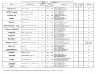
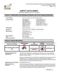
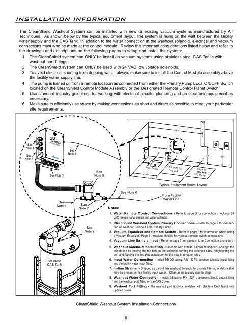
INSTALLATION INFORMATIONThe <strong>CleanShield</strong> Washout System can be installed with new or existing vacuum systems manufactured by <strong>Air</strong><strong>Techniques</strong>. As shown below by the typical equipment layout, the system is hung on the wall between the facilitywater supply and the CAS Tank. In addition to the water connection at the washout solenoid, electrical and vacuumconnections must also be made at the control module. Review the important considerations listed below and refer tothe drawings and descriptions on the following pages to setup and install the system:1 The <strong>CleanShield</strong> system can ONLY be install on vacuum systems using stainless steel CAS Tanks withwashout port fittings.2 The <strong>CleanShield</strong> system can ONLY be used with 24 VAC low voltage solenoids.3 To avoid electrical shorting from dripping water, always make sure to install the Control Module assembly abovethe facility water supply line.4 The pump is turned on from a remote location as connected from either the Primary Pump Local ON/OFF Switchlocated on the <strong>CleanShield</strong> Control Module Assembly or the Designated Remote Control Panel Switch.5 Use standard industry guidelines for working with electrical circuits, plumbing and on electronic equipment asnecessary.6 Make sure to efficiently use space by making connections as short and direct as possible to meet your particularsite requirements.48"SeeNote 1SeeNote 2SeeNote 44"12"18"4"12"1" 4"4"24"24"See Note 3SeeNote 5Floor Drain20"50"4, 8 or 20 GalCAS TankSingle orStac kedSTS PumpSeeNote 8StainlessCAS TankOUTSeeNote 7INSeeNote 9See Note 6Typical Equipment Room LayoutFrom FacilityWater LineNotes:1. Water Remote Control Connections - Refer to page 8 for connection of optional 24VAC remote panel switch and water solenoid.2. <strong>CleanShield</strong> Washout System Primary Connections - Refer to page 9 for connectionof Washout Solenoid and Primary Pump.3. Vacuum Equalizer and Remote Switch - Refer to page 9 for information when usinga Vacuum Equalizer. Page 11 provides details for various remote switch connections.4. Vacuum Line Sample Input - Refer to page 7 for Vacuum Line Connection procedure5. Washout Solenoid Installation - Solenoid with bracket shown as shipped. Change theorientation by loosing the top bolt on the solenoid, turning the solenoid body, retightening thebolt and flipping the bracket installation to the new orientation side.6. Input Water Connection - Install 3/8 OD tubing, P/N 19271, between solenoid input fittingand the facility water input fitting.7. In-line Strainer - Shipped as part of the Washout Solenoid to provide filtering of debris thatmay be present in the facility input water. Clean as necessary due to clogs.8. Washout Water Connection - Install 3/8 tubing, P/N 19271, between solenoid output fittingand the washout port fitting on the CAS Cover.9. Washout Port Fitting - The washout port is ONLY available with Stainless CAS Tanks withupdated covers.<strong>CleanShield</strong> Washout System Installation Connections6