Chilled Water Fan Coil Unit - Trane
Chilled Water Fan Coil Unit - Trane
Chilled Water Fan Coil Unit - Trane

You also want an ePaper? Increase the reach of your titles
YUMPU automatically turns print PDFs into web optimized ePapers that Google loves.
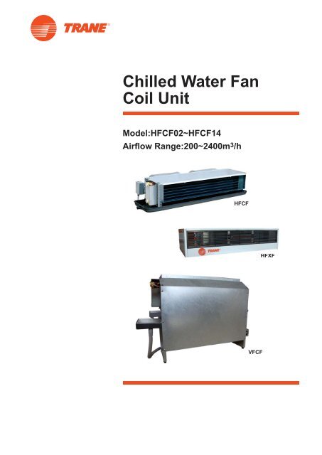
<strong>Chilled</strong> <strong>Water</strong> <strong>Fan</strong><strong>Coil</strong> <strong>Unit</strong>Model:HFCF02~HFCF14Airflow Range:200~2400m 3 /hHFCFHFXFVFCF
Features and BenefitsThe Best Choice for Comfort-■The Best Results- Quiet Comfort• Low noise permanent split capacitor motor.• Metal fan wheel both statically anddynamically balanced.• Threaded connection, match up ductcollars and keyholes for hangers shorteninstallation time.• Quick delivery helps meet tight installationschedules.- Latest Perfection• Cleaner, quieter and more effi cient fi ndesign.■The Best System- Design for comfort applications at home,offi ce and shop. HFCF is easily installedin a false ceiling or closet, HFCF is theideal solution for new or replacementapplications.■The Best Fit- Nine sizes to meet capacity requirements- One unit provides total comfortrequirements: both cooling and heating- Low height of just 230mm on all sizesmeans no diffi culty in fi tting tight ceilingapplicationsFilter (Option)<strong>Fan</strong>■Flexibility- Easy to change water hand connections onthe fi eld.■Reliability<strong>Trane</strong>’s history of innovation and technologyleadership led to quality products making<strong>Trane</strong> a leader in the air conditioning marketsworldwide. <strong>Trane</strong>’s commitment to customer’s needs for quality, effi ciency and reliability isevident from the largest chiller to smallest fancoil.<strong>Trane</strong>’s commitment to customer’s needsfor quality, effi ciency and reliability is evidentfrom the largest chiller to smallest fan coil.MotorPlenum (Option)<strong>Coil</strong> head supportJunction boxElectric heater (Option)Drain panDrain pan purgeAir vent<strong>Coil</strong><strong>Coil</strong> head supportHFCF AccessoriesLCD Thermostat (except for DCBL) ZN510/520 (for <strong>Trane</strong> ICS) Zone Sensor (for <strong>Trane</strong> ICS)TDG/Control Options<strong>Water</strong> Control Valve2
HFCF Model NomenclaturesH1F2C3F40536L738N9N10111N12A13N14A15N16N17A18Digit 1:Digit 2:Digit 3:Digit 4:Digit 5, 6:Digit 7:Digit 8:Digit 9:Digit 10:Digit 11:Digit 12:H = HorizontalF = <strong>Fan</strong> <strong>Coil</strong> <strong>Unit</strong> typeC = ConcealedF = Design SequenceSize / Nominal Airfl ow02 = 200 CFM03 = 300 CFM04 = 400 CFM05 = 500 CFM06 = 600 CFM08 = 800 CFM10 = 1000 CFM12 = 1200 CFM14 = 1400 CFMConnection SideL = Left ConnectionR = Right Connection<strong>Coil</strong> Rows2 = 2 Rows Cooling3 = 3 Rows Cooling4 = 4 Rows CoolingA = 2 Rows Cooling, 1 Row HeatingB = 3 Rows Cooling, 1 Row HeatingElectric Heater (Size)N = NoneA = 0.5 kW Heater (02)B = 1.0 kW Heater (03)C = 1.4 kW Heater (04)D = 1.6 kW Heater (05)E = 1.8 kW Heater (06)F = 2.8 kW Heater (08)G = 3.2 kW Heater (10)H = 3.6 kW Heater (12)J = 4.6 kW Heater (14)Motor TypeN = NormalH = High StaticA = DCBL Normal (w/ LCD Thermostat)B = DCBL High Static (w/ LCD Thermostat)C = Hermetic Motor Normal TypeD = Hermetic Motor High Static TypeVoltage/Hz/Phase1 = 220/50/12 = 220~240/60/13 = 115/60/1Factory Mounted Control / ValvePackageN = NoneA = 2-pipe, with 2-way ValveB = 2-pipe, with 3-way ValveC = 4-pipe, with 2-way ValvesD = 2-pipe, with 2-way Valve & LCDThermostatE = 2-pipe, with 2-way Valve & LCDThermostat (Confi gured with VWVSystem only)F = 2-pipe, with 3-way Valve & LCDThermostatDigit 13:Digit 14:Digit 15:G = 4-pipe, with 2-way Valves & LCDThermostatH = 2-pipe, with 2-way Valve & ZN510 w/Zone SensorJ = 2-pipe, with 3-way Valve & ZN510 w/Zone SensorK = 4-pipe, with 2-way Valves & ZN510 w/Zone SensorL = 2-pipe, with 2-way Valve & ZN520 w/Zone SensorM = 2-pipe, with 3-way Valve & ZN520 w/Zone SensorP = 4-pipe, with 2-way Valves & ZN520 w/Zone SensorQ = 2-pipe, with 2-way Floating Valve &ZN520 w/ Zone SensorR = 2-pipe, with 3-way Floating Valve &ZN520 w/ Zone SensorS = 4-pipe, with 2-way Floating Valves &ZN520 w/ Zone SensorTerminal BoxA = Standard Wiring w/ Terminal BoxB = Electric Heater Wiring w/ Terminal BoxC = DCBL Wiring w/ Terminal BoxD = ZN Wiring w/ Terminal BoxE = VWV w/ Terminal BoxReturn Plenum / FilterN = NoneA = with Rear Plenum OnlyB = with Rear Plenum/ 6mm Nylon FilterC = with Rear Plenum/ 20mm Aluminum FilterD = with Bottom Return Plenum OnlyE = with Bottom Return Plenum/ 6mm NylonFilterF = with Bottom Return Plenum/ 20mmAluminum FilterDrain PanA = STD. Galvanized Steel w/ 7mm PEInsulationB = STD. Galvanized Steel w/ 7mm PEInsulation & Extended 200mmC = STD. Galvanized Steel w/ 7mm PEInsulation & Extended 310mmD = Stainless Steel w/ 7mm PE InsulationE = Stainless Steel w/ 7mm PE Insulation &Extended 200mmF = Stainless Steel w/ 7mm PE Insulation &Extended 310mmG = STD. Galvanized Steel w/ 6mmNon-fl ammable Close Cell InsulationH = STD. Galvanized Steel w/ 6mmNon-fl ammable Close Cell Insulation &Extended 200mmJ = STD. Galvanized Steel w/ 6mmNon-fl ammable Close Cell Insulation &Extended 310mmK = Stainless Steel w/ 6mm Non-fl ammableClose Cell InsulationDigit 16:Digit 17:Digit 18:L = Stainless Steel w/ 6mm Non-fl ammableClose Cell Insulation & Extended200mmM = Stainless Steel w/ 6mm Non-fl ammableClose Cell Insulation & Extended310mmN = STD. Galvanized Steel w/ 10mmNon-fl ammable Close Cell InsulationP = STD. Galvanized Steel w/ 10mmNon-fl ammable Close Cell Insulation &Extended 200mmQ = STD. Galvanized Steel w/ 10mmNon-fl ammable Close Cell Insulation &Extended 310mmR = Stainless Steel w/ 10mm Non-fl ammableClose Cell InsulationS = Stainless Steel w/ 10mm Non-fl ammableClose Cell Insulation & Extended200mmT = Stainless Steel w/ 10mm Non-fl ammableClose Cell Insulation & Extended310mmU = STD. Galvanized Steel w/ 25mmNon-fl ammable Close Cell InsulationV = STD. Galvanized Steel w/ 25mmNon-fl ammable Close Cell Insulation &Extended 200mmW = STD. Galvanized Steel w/ 25mmNon-fl ammable Close Cell Insulation &Extended 310mmX = Stainless Steel w/ 25mm Non-fl ammableClose Cell InsulationY = Stainless Steel w/ 25mm Non-fl ammableClose Cell Insulation & Extended 200mmZ = Stainless Steel w/ 25mm Non-fl ammableClose Cell Insulation & Extended 310mm<strong>Trane</strong> Digital Grille(TDG)N = NoneA = with Remote Controller OnlyB = with TDG LCD Thermostat OnlyC = with TDG LCD Thermostat & RemoteControllerD = with Remote Controller & UV LightE = with TDG LCD Thermostat & UV LightF = with TDG LCD Thermostat, RemoteController & UV LightFuture UseN = NoneRegionA = APRB = MAIRC = LAR3
HFXF Model NomenclaturesH1F2X3F40536L738N9N10111N12A13B14A15N16N17A18Digit 1: H = HorizontalDigit 2: F = <strong>Fan</strong> <strong>Coil</strong> <strong>Unit</strong> typeDigit 3: X = ExposedDigit 4: F = Design SequenceDigit 5, 6: Size / Nominal Airfl ow02 = 200 CFM03 = 300 CFM04 = 400 CFM05 = 500 CFM06 = 600 CFM08 = 800 CFM10 = 1000 CFM12 = 1200 CFM14 = 1400 CFMDigit 7: Connection SideL = Left ConnectionR = Right ConnectionDigit 8: <strong>Coil</strong> Rows2 = 2 Rows Cooling3 = 3 Rows Cooling4 = 4 Rows CoolingDigit 9: Electric Heater (Size)N = NoneA = 0.5 kW Heater (02)B = 1.0 kW Heater (03)C = 1.4 kW Heater (04)D = 1.6 kW Heater (05)E = 1.8 kW Heater (06)F = 2.8 kW Heater (08)G = 3.2 kW Heater (10)H = 3.6 kW Heater (12)J = 4.6 kW Heater (14)Digit 10: Motor TypeN = NormalC = Hermetic Motor Normal TypeDigit 11: Voltage/Hz/Phase1 = 220/50/12 = 220~240/60/13 = 115/60/1Digit 12: Factory Mounted Control / Valve PackageN = NoneDigit 13: Terminal BoxA = Standard Wiring w/ Terminal BoxB = Electric Heater Wiring w/ Terminal BoxDigit 14: Return Plenum / FilterA = Standard with Return Plenum without fi lterB = Standard with Return Plenum/ 6mm Nylon FilterC = Standard with Return Plenum/ 20mm Aluminum fi lterDigit 15: Drain PanA = STD. Galvanized Steel w/ 7mm PE InsulationD = Stainless Steel w/ 7mm PE InsulationG = STD. Galvanized Steel w/ 6mmNon-fl ammable Close Cell InsulationK = Stainless Steel w/ 6mm Non-fl ammableClose Cell InsulationDigit 16: <strong>Trane</strong> Digital Grille(TDG)N = NoneDigit 17: Future UseN = NoneDigit 18: RegionA = APRB = MAIRC = LAR4
VFCF Model NomenclaturesV1F2C3F40536L738N9N10111N12A13B14A15N16N17A18Digit 1:Digit 2:Digit 3:Digit 4:Digit 5, 6:Digit 7:Digit 8:Digit 9:Digit 10:V = VerticalF = <strong>Fan</strong> <strong>Coil</strong> <strong>Unit</strong> typeC = ConcealedF = Design SequenceSize / Nominal Airfl ow02 = 200 CFM03 = 300 CFM04 = 400 CFM05 = 500 CFM06 = 600 CFM08 = 800 CFM10 = 1000 CFM12 = 1200 CFM14 = 1400 CFMConnection SideL = Left ConnectionR = Right Connection<strong>Coil</strong> Rows3 = 3 Rows CoolingElectric Heater (Size)N = NoneA = 0.5 kW Heater (02)B = 1.0 kW Heater (03)C = 1.4 kW Heater (04)D = 1.6 kW Heater (05)E = 1.8 kW Heater (06)F = 2.8 kW Heater (08)G = 3.2 kW Heater (10)H = 3.6 kW Heater (12)J = 4.6 kW Heater (14)Motor TypeN = NormalDigit 11:Digit 12:Digit 13:Digit 14:Digit 15:Digit 16:Digit 17:Digit 18:H = High StaticC = Hermetic Motor Normal TypeD = Hermetic Motor High Static TypeVoltage/Hz/Phase1 = 220/50/12 = 220~240/60/13 = 115/60/1Factory Mounted Control / ValvePackageN = NoneTerminal BoxA = Standard Wiring w/ Terminal BoxB = Electric Heater Wiring w/ Terminal BoxReturn Plenum / FilterB = with 6mm Nylon FilterDrain PanA = STD. Galvanized Steel w/ 7mm PE InsulationD = Stainless Steel w/ 7mm PE InsulationG = STD. Galvanized Steel w/ 6mmNon-fl ammable Close Cell InsulationK = Stainless Steel w/ 6mm Non-fl ammableClose Cell Insulation<strong>Trane</strong> Digital Grille(TDG)N = NoneFuture UseN = NoneRegionA = APRB = MAIRC = LAR5
Performance DataCooling Capacity (Example)Cooling Capacity : kW EWT : 7℃ Cooling Rows : 3 SH: Sensible Cooling Capacity, kWEAT : 27℃/ 50% LWT : 12℃ Motor Frequency: 50Hz/ 60Hz WPD: <strong>Water</strong> Pressure Drop, kPaESP : 12/50 Pa(Normal / Hi-Static) ESP : 12/50 Pa(Normal / Hi-Static) TH : Total Cooling Capacity, kW WFR: <strong>Water</strong> Flow Rate, L/SModel020304050608101214SpeedNominalAirflowDCBLNominal Cooling HeatingAirflow Cap. Cap.PowerDCBLPower220V/50Hz 220V/50HzNoise DCBLNoise<strong>Water</strong>flowWPDCoolingCap.HeatingCap.PowerDCBLPower220V/50Hz 220V/50HzNoise DCBLNoisem3/h m3/h kW kW w w dB(A) dB(A) l/s l/s kW kW w w dB(A) dB(A) l/s l/sSuper Hight - 380 2.45 3.57 - 17.2 - 352.40 3.50 - 38.6 - 40High 340 340 2.10 3.27 23 14.2 35 34 2.04 3.17 44 33.2 41 39Medium 260 260 1.63 2.66 18 9.2 27 25 0.108 10 1.59 2.57 34 25.4 38 35Low 190 190 1.21 2.06 15 8.4 23 21 1.18 2.00 29 15 28 26Super Low - 160 1.16 1.76 - 8.4 - 21 1.14 1.72 - 11.6 - 25Super Hight - 580 4.02 5.53 - 18.2 - 323.98 5.48 - 42.6 - 41High 510 510 3.41 5.01 29 15.2 32 31 3.31 5.19 56 39.2 42 40Medium 380 380 2.67 3.90 20 10.2 23 21 0.172 33 2.58 4.04 39 29.4 35 33Low 260 260 1.98 2.95 17 9.4 21 20 1.99 3.07 33 17 26 24Super Low - 230 1.91 2.58 - 9.4 - 20 1.89 2.56 - 11.6 - 23Super Hight - 780 4.91 7.09 - 37.2 - 374.77 6.88 - 55.3 - 44High 680 680 4.12 6.27 43 35.5 37 36 3.59 5.53 64 50 45 43Medium 490 490 3.30 4.95 32 18.4 29 27 0.209 19 2.87 4.37 48 28 38 35Low 340 340 2.56 3.76 27 13.9 23 21 2.22 3.32 40 17 27 25Super Low - 310 2.43 3.39 - 11.8 - 20 2.36 3.29 - 13.5 - 24Super Hight - 970 6.10 8.72 - 49.1 - 415.92 8.46 - 62.5 - 45High 850 850 5.06 7.78 67 46.1 42 40 4.94 7.65 85 59 46 44Medium 670 670 4.31 6.54 30 25.2 37 34 0.256 27 4.20 6.43 38 37.5 40 37Low 430 430 3.19 4.67 25 15.6 36 33 3.11 4.59 32 22 31 29Super Low - 390 3.07 4.18 - 13.4 - 30 2.98 4.06 - 13.5 - 28Super Hight - 1170 7.06 10.18 - 65.7 - 436.85 9.87 - 68 - 45High 1020 1020 5.99 9.02 77 60 43 42 5.64 8.85 92 66 47 44Medium 710 710 4.79 7.13 59 27 33 31 0.299 38 4.51 6.98 70 46 42 38Low 480 480 3.63 5.14 48 17.5 26 24 3.39 5.04 57 22 34 31Super Low - 390 3.18 4.28 - 14.2 - 24 3.09 4.15 - 13.5 - 30Super Hight - 1520 8.36 12.89 - 78.7 - 458.19 12.64 - 113.8 - 48High 1360 1360 7.33 11.85 117 75.8 45 44 7.28 11.94 145 102.8 50 47Medium 1020 1020 6.16 9.95 100 48.8 39 36 0.368 22 6.12 10.09 124 71.2 45 41Low 710 710 4.69 7.59 85 30.4 32 29 4.67 7.64 105 47.3 38 35Super Low - 580 3.89 6.14 - 23.6 - 28 3.81 6.02 - 26.3 - 34Super Hight - 1910 10.83 16.19 - 94.2 - 4410.61 15.86 - 139.8 - 50High 1700 1700 9.19 15.04 142 82.8 47 44 9.37 15.19 176 127.8 51 49Medium 1260 1260 7.71 12.48 110 53.5 38 35 0.459 28 7.87 12.61 136 84.7 44 41Low 850 850 5.79 9.33 87 32.2 27 24 5.91 9.42 108 49.8 34 32Super Low - 730 5.35 7.76 - 22.5 - 24 5.24 7.61 - 32.4 - 31Super Hight - 2260 12.76 18.93 - 132.8 - 4812.51 18.55 - 184.2 - 52High 2040 2040 10.75 17.52 173 120.9 50 48 11.23 18.02 214 161.2 54 51Medium 1670 1670 9.46 15.41 140 84.8 44 41 0.539 38 9.88 15.86 173 118.5 50 46Low 1150 1150 7.42 11.74 114 52.3 35 32 7.75 12.08 141 72.3 41 38Super Low - 780 5.97 8.39 - 26.3 - 31 5.85 8.22 - 36.8 - 37Super Hight - 2560 14.36 21.22 - 165.8 - 5013.92 20.58 - 222 - 55High 2380 2380 12.43 19.89 195 150 52 50 12.27 20.52 286 202 56 54Medium 1790 1790 10.81 17.30 170 97 46 43 0.625 49 10.68 17.85 257 131.4 49 46Low 1300 1300 8.94 13.73 148 68.4 39 36 8.84 14.15 217 68.9 38 36Super Low - 780 6.17 8.49 - 32.2 - 35 5.98 8.24 - 40 - 35<strong>Water</strong>flowWPD0.103 120.166 310.181 150.25 260.283 370.367 230.471 310.565 380.621 49Spec./ OptionsHFCF Rows ESP 02 03 04 05 06 08 10 12 14Input Power For 230V/ 60Hz W 3 Normal static 28 36 45 59 82 117 133 242 263115V/ 60Hz W 3 Normal static 28 34 52 60 78 99 133 218 291230V/ 60Hz W 3 High static 55 77 97 110 134 179 242 268 325115V/ 60Hz W 3 High static 54 87 93 117 143 175 156 293 367*Heater Capacity Type (kW) Hot water 1Row kW 2+1 12Pa 1.36 2.43 3.12 3.82 4.49 5.49 6.76 7.84 9.17EWT= 60℃; LWT=50℃; EAT=21℃ kW 2+1 12Pa 1.63 2.43 3.12 3.91 4.36 5.54 6.67 7.85 8.98kW 2+1 50Pa 1.32 2.35 3.09 3.86 4.24 5.43 6.73 7.96 9.30kW 2+1 50Pa 1.45 2.44 3.07 3.66 4.16 5.48 6.75 7.69 9.20kW 3+1 12Pa 1.92 3.14 3.76 4.66 5.54 6.74 8.38 9.80 11.46kW 3+1 12Pa 1.59 2.37 3.04 3.81 4.27 5.40 6.51 7.66 8.76kW 3+1 50Pa 1.87 3.04 3.75 4.70 5.18 6.65 8.36 9.97 11.67kW 3+1 50Pa 1.41 2.38 2.99 3.57 4.06 5.35 6.58 7.50 8.98*Electric Sheathed Element PTC electric heater W 0.5 1.0 1.4 1.6 1.8 2.8 3.2 3.6 4.6*Plenum / FiltersReturn air plenum with fi lters —— PP Nylon or aluminum6
Dimensional Data and WeightHFCF Standard <strong>Unit</strong>HFCF Bottom Return Plenum and FilterCentrifugal<strong>Fan</strong>MotorFour Hanger Holes See View AHanger Holes(number.6) See View AJunction BoxReturn PlenumCentrifugal <strong>Fan</strong>MotorFiltersD188211Drain connection3/4" MPTControl Box21112436ABC 29216AirOutlet10145111147 2448746419223012643ABC 29216Header of drain water(3/4 MPT)10Outlet145Outlet11152249924147226Rear returnintake198230243<strong>Coil</strong>Drain Pan<strong>Water</strong> Outlet 3/4"FPT14270<strong>Water</strong> Inlet 3/4" FPT<strong>Coil</strong>Drain Pan14Outlet water Collar3/4-inch female pipe thread(FPT)270Inlet water Collar3/4-inch female pipe thread(FPT)HFCF Rear Return Plenum and FilterReturn PlenumSix Hanger Holes See View ACentrifugal <strong>Fan</strong>Motor FilterDView A111522499621118818Junction Box14Drain connection3/4" MPT1243ABC 291024226Rear ReturnPlenum Box216AirOutlet14514719823024311<strong>Coil</strong>Drain Pan14270<strong>Water</strong> Outlet 3/4"FPT <strong>Water</strong> Inlet 3/4" FPTNote:1.Dimension in mm.2.Above shown with right hard coil connection3.Wiring connection is located at the same side as coil and drain connections.4.Wiring and junction box will be supplied by <strong>Trane</strong>.Dimension (mm)MotorQty.<strong>Fan</strong>Qty.Net Weight (kg)wihout Plenum Box and FilterNet Weight (kg)wihout Plenum Box and Filter<strong>Unit</strong> ModelNormal Static High Static Normal Static High StaticA B C D 2 Row 3 Row 4 Row 2 Row 3 Row 4 Row 2 Row 3 Row 4 Row 2 Row 3 Row 4 RowHFCF02 458 485 648 547 1 1 12 13 14 13 14 15 15 16 17 16 17 18HFCF03 693 720 883 782 1 2 16 18 20 17 19 21 20 22 24 21 24 25HFCF04 793 820 983 882 1 2 17 19 21 18 20 22 21 23 25 22 25 26HFCF05 913 940 1103 1002 1 2 19 21 23 20 22 24 24 26 28 24 28 28HFCF06 963 990 1153 1052 1 2 20 22 24 21 23 25 25 27 29 25 29 29HFCF08 1243 1270 1433 1332 2 3 28 30 32 29 31 33 34 36 38 35 38 39HFCF10 1493 1520 1683 1582 2 4 30 33 36 32 35 38 37 40 43 39 43 45HFCF12 1663 1690 1853 1752 2 4 35 38 41 36 39 42 43 46 49 44 49 50HFCF14 1793 1820 1983 1882 2 4 37 40 43 38 41 44 45 48 51 46 51 527
Dimensional Data and WeightHFXF55C96VIEW A1881814211(545)1156B 127Hanger Holes(number. 6)see View AControl Box54515534A21 2120255193147255155OutletOutlet water Collar3/4-inch female pipe threadInlet water Collar3/4-inch female pipe threadNote:1.Dimension in mm.2.Above shown with right hard coil connection3.Wiring connection is located at the same side as coil and drain connections.4.Wiring and junction box will be supplied by <strong>Trane</strong>.Dimension (mm)MotorQty.<strong>Fan</strong>Qty.Net Weight (kg)<strong>Unit</strong> Model2 Row 3 Row 4 RowA B C kg kg kgHFXF02 867 485 547 1 1 25 25 27HFXF03 1102 720 782 1 2 31 33 35HFXF04 1202 820 882 1 2 32 34 36HFXF05 1322 940 1002 1 2 36 38 40HFXF06 1372 990 1052 1 2 38 40 42HFXF08 1652 1270 1332 2 3 49 51 53HFXF10 1902 1520 1582 2 4 53 56 59HFXF12 2072 1690 1752 2 4 61 64 67HFXF14 2202 1820 1882 2 4 63 66 698
Dimensional Data and WeightVFCF<strong>Coil</strong>8713423245 ALOutlet162946076Drain Pan620113Outlet water Collar3/4-inch female pipe thread(FPT)8Inlet water Collar3/4-inch female pipe thread(FPT)247Drain HoseCentrifugal <strong>Fan</strong> Motor Inlet Adjusting screwControl BoxNote:1.Dimension in mm.2.Above shown with right hard coil connection3.Wiring connection is located at the same side as coil and drain connections.4.Wiring and junction box will be supplied by <strong>Trane</strong>.Dimension (mm)MotorQty.<strong>Fan</strong>Qty.Net Weight (kg)<strong>Unit</strong> Model3 RowA L kgVFCF02 867 485 1 1 17VFCF03 1102 720 1 2 23VFCF04 1202 820 1 2 25VFCF05 1322 940 1 2 28VFCF06 1372 990 1 2 29VFCF08 1652 1270 2 3 37VFCF10 1902 1520 2 4 42VFCF12 2072 1690 2 4 47VFCF14 2202 1820 2 4 519
Sound Pressure Data/Wiring Diagram/<strong>Coil</strong> ConnectionSound Pressure DataPiping ConnectionMotor Type Normal Hi-Static<strong>Unit</strong>Octave Band (dB) & Center Frequency (Hz) Octave Band (dB) & Center Frequency (Hz)SpeedModel63 125 250 500 1000 2000 4000 8000 63 125 250 500 1000 2000 4000 8000020304050608101214High 20 15 25 27 31 29 17 10 19 24 28 33 37 37 25 13Med 20 14 19 23 23 19 11 9 19 22 26 31 34 33 21 11Low 19 13 15 19 21 11 11 9 19 15 17 23 24 22 12 9High 12 12 21 28 28 24 14 11 16 24 28 35 38 37 27 13Med 10 8 13 19 18 14 13 11 11 19 22 29 31 29 17 9Low 13 4 6 15 16 11 12 11 6 13 14 22 23 18 11 9High 16 17 25 31 33 32 18 9 15 26 33 38 41 39 28 15Med 17 16 18 25 25 21 11 9 17 21 25 32 34 31 19 10Low 17 16 15 19 19 11 10 8 13 12 16 23 24 17 11 9High 18 19 34 35 37 37 25 12 14 29 33 39 42 41 31 19Med 20 17 27 31 33 30 18 12 12 23 29 33 36 34 23 11Low 29 24 28 31 32 27 24 21 12 16 20 27 28 22 13 9High 17 19 32 36 39 38 27 14 17 31 34 39 43 42 33 20Med 19 14 22 28 29 26 15 9 21 26 30 35 38 37 26 13Low 17 11 14 22 22 14 10 9 14 19 23 30 31 26 16 10High 19 23 32 37 39 41 31 16 18 32 36 41 45 46 38 25Med 26 20 28 32 33 34 21 10 17 27 31 37 41 41 31 18Low 19 18 25 27 28 25 14 10 16 21 25 32 34 32 22 12High 18 22 33 39 42 42 31 19 17 32 36 43 47 46 38 26Med 19 17 25 32 34 31 19 11 16 26 30 37 40 38 29 16Low 18 14 15 24 23 16 11 9 14 19 22 29 30 26 16 12High 19 26 37 42 45 45 35 21 19 36 41 47 50 49 41 28Med 15 25 32 38 39 37 26 16 17 32 37 44 46 45 35 21Low 13 19 24 30 31 26 15 10 14 24 29 35 37 35 23 11High 16 28 41 45 47 47 38 25 22 38 43 49 52 51 44 31Med 15 25 36 40 42 40 29 16 21 32 37 42 45 44 34 21Low 14 22 27 36 34 30 18 11 20 23 27 33 34 30 19 13230188241474851486,4120,0284,0145,0122,048,02, 3, 4 Row1451224974,0123,048,0487Cold water outHot water out23,951,0147,0 188,1 230,9Notes:Above performance determined with both Normal static motor and Hi-static motor operating at0 Pa ESP (no ducting, ceiling enclosed or other sound attenuating materials used).74 120123284Hot water inCold water inWiring Diagram2+1 RowCCMOTORMOTORWHITEREDBLUEBLACK(Neutral)Model 08,10,12,14 only(Hi)(Med)(Low)WHITE(Neutral)1RED (Hi)2BLUE (Me)3BLACK (Low)4220V 50Hz 1P230V 60Hz 1P115V 60Hz 1PL NLNHiThermostatMedLow230188147 24485114512249487Cold water outHot water outAuto Reset1st Electric HeaterAuto Reset2nd Electric HeaterFuseFuseBLACKREDBLACKREDOPTION56NL220V 50Hz 1P230V 60Hz 1P115V 60Hz 1P74 120123284Hot water inCold water inNotes:1.Model speed controlYellow and Red Wires = High SpeedYellow and Blue Wires = Medium SpeedYellow and Black Wires = Low Speed2.Contactor or relay shall be installed by others for anelectric heater option3+1 Row10
Product Specification■ General• Fabricated with a rigid galvanized steelcasing. The HFXF outside cabinet is withpowder coating.• The DIDW centrifugal fans have balanced,galvanized steel, and forward curvedblades.• The fan board and the top of coil casingwere insulated with high-density nonflammable foam.• The coil casing shall be provided withcollars ,with screw holes for supply air ductand plenum box connections.■ <strong>Fan</strong> & Motor• Motors are of permanent split capacitortype for maximum effi ciency and minimumnoise with permanently lubricated, sealedball bearings.• <strong>Fan</strong> motor shall be capable of providing atleast 3 fan speeds( LOW-MEDIUM-HIGH)and built-in with thermal cut-out to preventoverloading at any speed and duty of thefans.• The motor capacitor is totally enclosed ina metal shield, and attached to the motor.The motor lead-out wires are enclosed in afl exible metal conduit to provide protectionagainst damage, and factory wired to aterminal block inside a factory installedjunction box.• An optional item of hermetic fan motor shallbe identical performance as typical underrated of IP21 or equivalent.• Optional DC motor is available for customerchoice (except HFXF and VFCF).• The motor shall be with CE and GB safetycertifi ed.■ <strong>Coil</strong>• The coil shall have 2,3 or 4 rowsconfi guration with seamless copper tubesmechanically bonded into blue aluminumfi ns and collars.• The coil shall be designed with bottomaccessible for ease of switching coil hands/water connections at jobsite.• <strong>Water</strong> inlet /outlet connections shallbe with 3/4-inch female pipe thread(GBT19001-2000). Header assembly shallbe one-piece brass casting which acceptssteel pipe directly.• <strong>Coil</strong>s are 3/8 inch OD copper tubesmechanically bonded into aluminum bluefi ns.• The coil standard provide blue fi n. The bluecoating is a vinyl-epoxy-based coating.• A manual air vent shall be fi tted with a draintube to the drain pan to avoid any waterdrips when venting. A water plug is locatedat the bottom of the coil header.• <strong>Coil</strong> assembly shall be tested over 25kg/cm2 (360 psi), no obvious leakage underworking pressure at 16kg/cm2 (230 psi).• A water drain pan purge is located at thebottom of the coil header• Interchangeable coil hand connections forHFCF(2/3/4 row) only.■ Drain Pan• The drain pan shall be thermally insulatedgalvanized steel, pretreated with epoxyresin coating at an inner surface.• For maximum security from leaks, drain panshall be one-piece stamping with no seamor joint .• The standard insulation material is 27kg/m3 density PE foam. And the thickness is7mm. 6/10/25mm thickness non-fl ammableclose cell insulation is available for option.• The drain pan shall have galvanized steelmale with 3/4-inch connection.• The drain pan shall be removable and havea slight fall towards the drain connection.<strong>Fan</strong> <strong>Coil</strong> Options■ Heater• Either hot water heating or positivetemperature coeffi cient (PTC) electric heateris available as for heating option.• One row heating coil for HFCF(2+1 / 3+1).■ Plenum & Filter• The fi lter shall be selected with permanent,dry type, washable nylon or fl ameproofaluminum foil(except VFCF).• Optional bottom return air plenum or rearreturn air plenum for HFCF.■ Stainless Steel Drain Pan• The material shall have graded SUS 304 orequivalent.■ Factory-mounted Control valvePackage for HFCF• Factory mounted 2-way or 3-way controlvalve with fi tting to the coil, it shall be testedagainst the maximum working pressure ofcoil.• Factory mounted and functional test donefor <strong>Trane</strong> ICS fan coil controller. All cablesare wired to a terminal block inside a factoryinstalled junction box.■ <strong>Trane</strong> Build Management System• The Tracer Summit system is designedfor monitoring and control air conditioningsystem, lighting and other controllabledevices for building.• Such Building Control <strong>Unit</strong> (BCU) managesall <strong>Unit</strong> Control Modules (UCM) for differentzones management. Each UCM performsscan on couples of HFCF equips ZNcontroller in specifi c zone and regularlyreport to the central system.■ DC <strong>Fan</strong> Motor for HFCF• Energy saving/ high effi ciency, low electromagnetic noise.• More accurate temperature control(±0.5deg. C) and low running noise at auto mode• Variable airfl ow (lowest at 30%) bybrushless DC fan motor, achieve ofcomfortable room temperature.• <strong>Fan</strong> motor comes with specifi c controllerand backlight LCD thermostat, key cardwith standalone confi guration.11
The <strong>Trane</strong> <strong>Fan</strong> <strong>Coil</strong>.....Invented by <strong>Trane</strong>...Perfected by <strong>Trane</strong>.Since 1885, <strong>Trane</strong> has been atthe technological forefront of airconditioning. The company's pioneeringspirit, commitment to research andpursuit of quality have made it a worldleader in the manufacture of waterchillers.Over 70 years ago <strong>Trane</strong> produced thefi rst fan coil unit and in so doing createda product which is now built worldwide.The universal acceptance of thisproduct has prompted <strong>Trane</strong> to focusthe same engineering experience tothe fan coil as given to the refrigerationproducts.www.trane.comLiterature Order NumberDateSupersedesUNT-PRC010-ENMay 2009June 2008For more information, contact your local <strong>Trane</strong>offi ce or e-mail us at comfort@trane.com<strong>Trane</strong> has a policy of continuous product and data improvement and reserves the right to change designspecifi cations without notice.