Thermal Matching of a Thermoelectric Energy Scavenger with the ...
Thermal Matching of a Thermoelectric Energy Scavenger with the ...
Thermal Matching of a Thermoelectric Energy Scavenger with the ...

You also want an ePaper? Increase the reach of your titles
YUMPU automatically turns print PDFs into web optimized ePapers that Google loves.
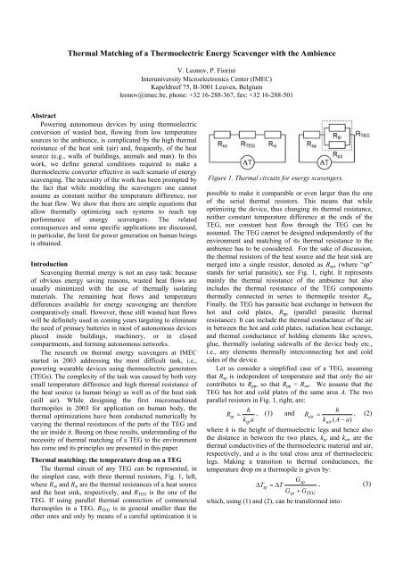
<strong>Thermal</strong> <strong>Matching</strong> <strong>of</strong> a <strong>Thermoelectric</strong> <strong>Energy</strong> <strong>Scavenger</strong> <strong>with</strong> <strong>the</strong> AmbienceV. Leonov, P. FioriniInteruniversity Microelectronics Center (IMEC)Kapeldreef 75, B-3001 Leuven, Belgiumleonov@imec.be, phone: +32 16-288-367, fax: +32 16-288-501AbstractPowering autonomous devices by using <strong>the</strong>rmoelectricconversion <strong>of</strong> wasted heat, flowing from low temperaturesources to <strong>the</strong> ambience, is complicated by <strong>the</strong> high <strong>the</strong>rmalresistance <strong>of</strong> <strong>the</strong> heat sink (air) and, frequently, <strong>of</strong> <strong>the</strong> heatsource (e.g., walls <strong>of</strong> buildings, animals and man). In thiswork, we define general conditions required to make a<strong>the</strong>rmoelectric converter effective in such scenario <strong>of</strong> energyscavenging. The necessity <strong>of</strong> <strong>the</strong> work has been prompted by<strong>the</strong> fact that while modeling <strong>the</strong> scavengers one cannotassume as constant nei<strong>the</strong>r <strong>the</strong> temperature difference, nor<strong>the</strong> heat flow. We show that <strong>the</strong>re are simple equations thatallow <strong>the</strong>rmally optimizing such systems to reach topperformance <strong>of</strong> energy scavengers. The relatedconsequences and some specific applications are discussed,in particular, <strong>the</strong> limit for power generation on human beingsis obtained.IntroductionScavenging <strong>the</strong>rmal energy is not an easy task: because<strong>of</strong> obvious energy saving reasons, wasted heat flows areusually minimized <strong>with</strong> <strong>the</strong> use <strong>of</strong> <strong>the</strong>rmally isolatingmaterials. The remaining heat flows and temperaturedifferences available for energy scavenging are <strong>the</strong>reforecomparatively small. However, <strong>the</strong>se still wasted heat flowswill be definitely used in coming years targeting to eliminate<strong>the</strong> need <strong>of</strong> primary batteries in most <strong>of</strong> autonomous devicesplaced inside buildings, machinery, or in closedcompartments, and forming autonomous networks.The research on <strong>the</strong>rmal energy scavengers at IMECstarted in 2003 addressing <strong>the</strong> most difficult task, i.e.,powering wearable devices using <strong>the</strong>rmoelectric generators(TEGs). The complexity <strong>of</strong> <strong>the</strong> task was caused by both verysmall temperature difference and high <strong>the</strong>rmal resistance <strong>of</strong><strong>the</strong> heat source (a human being) as well as <strong>of</strong> <strong>the</strong> heat sink(still air). While designing <strong>the</strong> first micromachined<strong>the</strong>rmopiles in 2003 for application on human body, <strong>the</strong><strong>the</strong>rmal optimizations have been conducted numerically byvarying <strong>the</strong> <strong>the</strong>rmal resistances <strong>of</strong> <strong>the</strong> parts <strong>of</strong> <strong>the</strong> TEG and<strong>the</strong> air inside it. Basing on <strong>the</strong>se results, understanding <strong>of</strong> <strong>the</strong>necessity <strong>of</strong> <strong>the</strong>rmal matching <strong>of</strong> a TEG to <strong>the</strong> environmenthas come and its principles are presented in this paper.<strong>Thermal</strong> matching: <strong>the</strong> temperature drop on a TEGThe <strong>the</strong>rmal circuit <strong>of</strong> any TEG can be represented, in<strong>the</strong> simplest case, <strong>with</strong> three <strong>the</strong>rmal resistors, Fig. 1, left,where R so and R si are <strong>the</strong> <strong>the</strong>rmal resistances <strong>of</strong> a heat sourceand <strong>the</strong> heat sink, respectively, and R TEG is <strong>the</strong> one <strong>of</strong> <strong>the</strong>TEG. If using parallel <strong>the</strong>rmal connection <strong>of</strong> commercial<strong>the</strong>rmopiles in a TEG, R TEG is in general smaller than <strong>the</strong>o<strong>the</strong>r ones and only by means <strong>of</strong> a careful optimization it isFigure 1. <strong>Thermal</strong> circuits for energy scavengers.possible to make it comparable or even larger than <strong>the</strong> one<strong>of</strong> <strong>the</strong> serial <strong>the</strong>rmal resistors. This means that whileoptimizing <strong>the</strong> device, thus changing its <strong>the</strong>rmal resistance,nei<strong>the</strong>r constant temperature difference at <strong>the</strong> ends <strong>of</strong> <strong>the</strong>TEG, nor constant heat flow through <strong>the</strong> TEG can beassumed. The TEG cannot be designed independently <strong>of</strong> <strong>the</strong>environment and matching <strong>of</strong> its <strong>the</strong>rmal resistance to <strong>the</strong>ambience has to be considered. For <strong>the</strong> sake <strong>of</strong> discussion,<strong>the</strong> <strong>the</strong>rmal resistors <strong>of</strong> <strong>the</strong> heat source and <strong>the</strong> heat sink aremerged into a single resistor, denoted as R sp , (where “sp”stands for serial parasitic), see Fig. 1, right. It representsmainly <strong>the</strong> <strong>the</strong>rmal resistance <strong>of</strong> <strong>the</strong> ambience but alsoincludes <strong>the</strong> <strong>the</strong>rmal resistance <strong>of</strong> <strong>the</strong> TEG components<strong>the</strong>rmally connected in series to <strong>the</strong>rmopile resistor R tp .Finally, <strong>the</strong> TEG has parasitic heat exchange in between <strong>the</strong>hot and cold plates, R pp (parallel parasitic <strong>the</strong>rmalresistance). It can include <strong>the</strong> <strong>the</strong>rmal conductance <strong>of</strong> <strong>the</strong> airin between <strong>the</strong> hot and cold plates, radiation heat exchange,and <strong>the</strong>rmal conductance <strong>of</strong> holding elements like screws,glue, <strong>the</strong>rmally isolating sidewalls <strong>of</strong> <strong>the</strong> device body etc.,i.e., any elements <strong>the</strong>rmally interconnecting hot and coldsides <strong>of</strong> <strong>the</strong> device.Let us consider a simplified case <strong>of</strong> a TEG, assumingthat R sp is independent <strong>of</strong> temperature and that only <strong>the</strong> aircontributes to R pp , so that R pp = R air . We assume that <strong>the</strong>TEG has hot and cold plates <strong>of</strong> <strong>the</strong> same area A. The twoparallel resistors in Fig. 1, right, are:hRtp = , (1) andhRair= , (2)ktpakair( A − a)where h is <strong>the</strong> height <strong>of</strong> <strong>the</strong>rmoelectric legs and hence also<strong>the</strong> distance in between <strong>the</strong> two plates, k tp and k air are <strong>the</strong><strong>the</strong>rmal conductivities <strong>of</strong> <strong>the</strong> <strong>the</strong>rmoelectric material and air,respectively, and a is <strong>the</strong> total cross area <strong>of</strong> <strong>the</strong>rmoelectriclegs. Making a transition to <strong>the</strong>rmal conductances, <strong>the</strong>temperature drop on a <strong>the</strong>rmopile is given by:Gsp∆ Ttp= ∆T, (3)Gsp+ GTEGwhich, using (1) and (2), can be transformed into:
Gsph∆ Ttp= ∆T. (4)Gsph+ ktpa+ kair( A − a)The open circuit voltage is given by:α ∆T GsphV =, (5)( Gsph+ kairA)+ a ( ktp− kair)where α is Seebeck coefficient. Expressing <strong>the</strong> electricalresistance <strong>of</strong> a <strong>the</strong>rmopile through its resistivity ρ, <strong>the</strong> poweron <strong>the</strong> matched electrical load can be written as:222spα ∆TG haPel=4 ⋅, (6)ρ2[( Gsph+ K air A)+ a(ktp− k air )]At its derivative dP el /da = 0, <strong>the</strong> maximal powercorresponds to a = a opt = (G sp h + k air A) / ( k tp – k air ), sothat:2α ∆TG hPmax=. (7)216ρ( ktp− kair)Substituting a opt into Eq. (4), <strong>the</strong> temperature difference∆T tp , corresponding to <strong>the</strong> maximal power, is:tp,opt22sp∆TG∆ T =, (8)sp⋅2 Gsp+ GTEG,0where G TEG,0 = k air A / h denotes <strong>the</strong> <strong>the</strong>rmal conductance <strong>of</strong><strong>the</strong> same TEG, but <strong>with</strong> no <strong>the</strong>rmocouples in between <strong>the</strong>plates, i.e., <strong>of</strong> <strong>the</strong> empty TEG; this is <strong>the</strong> parasitic <strong>the</strong>rmalconductance <strong>of</strong> a TEG. Eq. (8) shows that if <strong>the</strong> <strong>the</strong>rmalconductance <strong>of</strong> <strong>the</strong> air in empty TEG G TEG,0 > Ramb,0(13) and RTEG 0R amb , opt,>> . (14)In <strong>the</strong> optimized device, Inequalities (13) and (14) shouldhold, at least in a weak form (<strong>with</strong> “much more” replaced<strong>with</strong> “more”), fur<strong>the</strong>rmore, in typical situations <strong>of</strong> <strong>the</strong> energyscavengers, <strong>the</strong> ambient resistance does not vary greatly<strong>with</strong> temperature. For <strong>the</strong>se reasons, Eq. (12) instead <strong>of</strong> Eq.(11) can be usually used as a condition for optimizing <strong>the</strong>device.Considering that∆T TEG,0 = R TEG,0 W TEG,0 and ∆T TEG,opt = R TEG,opt W TEG,opt , (15)<strong>the</strong> condition <strong>of</strong> Eq. (12) can be rewritten as:R TEG,opt W TEG,opt = R TEG,0 W TEG,0 /2 . (16)In those cases, where <strong>the</strong> <strong>the</strong>rmal resistance <strong>of</strong> <strong>the</strong> ambiencedominates, <strong>the</strong> heat flow does not depend on <strong>the</strong> <strong>the</strong>rmalresistance <strong>of</strong> a TEG, and Eq. (16) simplifies to:R TEG,opt = R TEG,0 /2 , (17)<strong>the</strong>reby stating that <strong>the</strong> <strong>the</strong>rmal resistance <strong>of</strong> <strong>the</strong>rmocouplesand <strong>of</strong> <strong>the</strong> air are equal to each o<strong>the</strong>r. This condition iswidely used in designing <strong>the</strong> TEGs. As <strong>the</strong> goal <strong>of</strong> <strong>the</strong>optimization is to make <strong>the</strong> <strong>the</strong>rmal resistance <strong>of</strong> <strong>the</strong> TEGcomparable or larger than <strong>the</strong> one <strong>of</strong> <strong>the</strong> ambience, in mostcases, Eq. (17) cannot be used and must be replaced <strong>with</strong>Eq. (12) or, even better, <strong>with</strong> Eq. (11).We proceed now <strong>with</strong> <strong>the</strong> optimization <strong>of</strong> <strong>the</strong> TEG. First,we replace ∆T TEG,opt and ∆T TEG,0 in Eq. (11) <strong>with</strong> Eqs. (15).Then we eliminate <strong>the</strong> heat flows using:∆TWTEG,0= , (18)R + RWTEG,optamb,0amb,optTEG,0∆T= . (19)R + RTEG,optAfter such replacements, we solve Eq. (11) for R TEG,opt andobtain:RTEG,optRamb,optRTEG,0= . (20)2Ramb,opt+ RTEG,0Eq. (20) can be solved by iterations. In <strong>the</strong> beginning, <strong>the</strong>value <strong>of</strong> R amb,0 can be used instead <strong>of</strong> R amb,opt . Uponobtaining <strong>the</strong> first approximation value <strong>of</strong> R TEG,opt , <strong>the</strong> values<strong>of</strong> W TEG,opt and R amb,opt can be recalculated more accurately;<strong>the</strong> latter <strong>the</strong>n can be used in <strong>the</strong> next iteration. Only severaliterations are usually required for excellent accuracy.
As far as only two parallel <strong>the</strong>rmal resistors compose <strong>the</strong>TEG, <strong>the</strong> required <strong>the</strong>rmal resistance <strong>of</strong> <strong>the</strong> <strong>the</strong>rmopile R tp,optcan be easily obtained from <strong>the</strong> value <strong>of</strong> ∆T TEG,opt . Theoptimal area <strong>of</strong> <strong>the</strong>rmoelectric material a in <strong>the</strong> TEG is:a opt h / ktpRtp,opt= . (21)The minimal number <strong>of</strong> <strong>the</strong>rmocouple legs, while satisfying<strong>the</strong> requirement for <strong>the</strong> output voltage on <strong>the</strong> matched loadV m , is given by:2Vmn = . (22)α ∆TTEG,optFinally, <strong>the</strong> required cross section s <strong>of</strong> <strong>the</strong>rmopile legsshould not exceed s = a / n .<strong>Thermal</strong> matching: <strong>the</strong> application on manAs an example <strong>of</strong> application <strong>of</strong> <strong>the</strong> method described,let us consider a <strong>the</strong>rmopile <strong>with</strong> <strong>the</strong> same minimal lateralleg dimensions as in [1] <strong>with</strong> <strong>the</strong>ir size <strong>of</strong> 80 µm × 80 µm ×600 µm. For calculations, we assume that <strong>the</strong> hot plate has a<strong>the</strong>rmal contact <strong>with</strong> <strong>the</strong> skin in <strong>the</strong> outer side <strong>of</strong> <strong>the</strong> wristover a circular area <strong>of</strong> 3.14 cm 2 , while <strong>the</strong> radiating area is 7cm 2 , so that <strong>the</strong> device body resembles a watch. The hot andcold plates are separated by 1.3 mm, which is <strong>the</strong> thickness(1), however, this is because in our device <strong>the</strong> Inequalities(13) and (14), even in <strong>the</strong>ir weak form, are not satisfied.Small-size <strong>the</strong>rmopiles available on <strong>the</strong> market do not fit<strong>the</strong> requirements for <strong>the</strong> <strong>the</strong>rmopile legs coming out <strong>of</strong> <strong>the</strong>modeling <strong>of</strong> an optimal <strong>the</strong>rmopile because <strong>the</strong>ir aspect ratiois much smaller than needed. An appropriate aspect ratio<strong>the</strong>n can be obtained by stacking <strong>the</strong>rmopiles on top <strong>of</strong> eacho<strong>the</strong>r [2]. This increases <strong>the</strong> R TEG and hence <strong>the</strong> outputpower. For example, in case <strong>of</strong> a 10-stage <strong>the</strong>rmopile, <strong>the</strong>power increases in 5.7 times. Larger number <strong>of</strong> stages couldfur<strong>the</strong>r increase <strong>the</strong> power, but <strong>the</strong> device would be too thickand <strong>the</strong>refore inconvenient for <strong>the</strong> users.The normalized power for a 10-stage TEG, Fig. 2,coincides <strong>with</strong> <strong>the</strong> similar curve for a one-stage device. Theheat flow is, however, different. Inequality (14), even in itsweak form, is not yet satisfied in <strong>the</strong> 10-stage TEG; <strong>the</strong>R TEG,0 is still 84% <strong>of</strong> R amb,opt , however, <strong>the</strong> change in heatflow is already 44% at <strong>the</strong> matching point (1). It fur<strong>the</strong>rFigure 2. <strong>Thermal</strong> matching <strong>of</strong> a TEG to <strong>the</strong> ambience:normalized power (solid line) and normalized heat flow(dashed lines). The arrows show <strong>the</strong> heat flowscorresponding to three marked points.<strong>of</strong> <strong>the</strong> <strong>the</strong>rmopile including <strong>the</strong> ceramic plates. The powerproduced depends on <strong>the</strong> number <strong>of</strong> <strong>the</strong>rmocouple legs,<strong>the</strong>refore, at a certain number, corresponding to <strong>the</strong> optimalcross area <strong>of</strong> <strong>the</strong>rmoelectric material, <strong>the</strong> matching condition<strong>of</strong> Eq. (11) is satisfied. The normalized power computednumerically for an air temperature <strong>of</strong> 22 °C is shown in Fig.2 versus <strong>the</strong> ∆T TEG /∆T TEG,0 ratio. Each point <strong>of</strong> <strong>the</strong> curvecorresponds to a different value <strong>of</strong> a. The maximal power,point (1), is observed at ∆T TEG = ∆T TEG,0 /2.The analysis <strong>of</strong> numerical simulations shows that this isbecause <strong>the</strong> ambient resistance is only weakly dependent ontemperature. In addition, <strong>the</strong> <strong>the</strong>rmal resistance <strong>of</strong> <strong>the</strong>ambience is larger than <strong>the</strong> one <strong>of</strong> <strong>the</strong> generator. So, <strong>the</strong>device is in a condition, where <strong>the</strong> heat flow is nearlyindependent <strong>of</strong> R TEG , Fig. 2, so that Eq. (17) approximatelyholds. Using Eq. (17) for determining <strong>the</strong> number <strong>of</strong><strong>the</strong>rmocouples corresponding to <strong>the</strong> optimal power wouldhave generated a small error giving <strong>the</strong> point (2), Fig. 2. Onemay see that it is not very far from <strong>the</strong> true matching pointFigure 3. The ratios <strong>of</strong> <strong>the</strong> <strong>the</strong>rmal resistance <strong>of</strong> <strong>the</strong><strong>the</strong>rmopile and <strong>of</strong> <strong>the</strong> TEG to <strong>the</strong> one <strong>of</strong> <strong>the</strong> ambience versus<strong>the</strong> number <strong>of</strong> stages at <strong>the</strong>rmal matching, i.e., at a=a opt .increases after satisfying Inequality (14) in its weak form.This confirms that heat flow cannot be assumed as constantwhile modeling and that Eq. (17) cannot be used foroptimization: its use would have given <strong>the</strong> point indicated as(3) in Fig. 2, far away from real maximum.The ratios R TEG,opt /R amb,opt and R tp,opt /R amb,opt are shown inFig. 3 versus <strong>the</strong> number <strong>of</strong> stages. One can notice that <strong>the</strong><strong>the</strong>rmal resistance <strong>of</strong> a TEG does not halve at <strong>the</strong> matchingpoint (i.e., R TEG,opt ≠ R tp,opt /2), reflecting <strong>the</strong> difference <strong>with</strong>both parallel and serial matching.Some aspects <strong>of</strong> <strong>the</strong>rmal matching <strong>of</strong> TEGs on humansAs shown above, multi-stage <strong>the</strong>rmopiles allow <strong>the</strong><strong>the</strong>rmal matching, but it occurs at a very high effectiveaspect ratio, which is <strong>the</strong> ratio <strong>of</strong> <strong>the</strong> length <strong>of</strong> all <strong>the</strong><strong>the</strong>rmocouple legs on top <strong>of</strong> each o<strong>the</strong>r to <strong>the</strong>ir width. Thereare, however, some o<strong>the</strong>r helpful practical ways <strong>of</strong> easilytuning <strong>the</strong> <strong>the</strong>rmal resistance <strong>of</strong> <strong>the</strong> TEG components t<strong>of</strong>ulfill <strong>the</strong> <strong>the</strong>rmal matching requirements at smaller aspectratio or at smaller number <strong>of</strong> <strong>the</strong> stages.First, when applying <strong>the</strong>rmal matching conditions to <strong>the</strong>TEG on human skin, Inequality (14) in its weak formdemands to provide a <strong>the</strong>rmal plate-to-plate isolation <strong>of</strong> atleast 2 000 cm 2 K/W, which can be done only at <strong>the</strong>irdistance <strong>of</strong> about 1 cm from each o<strong>the</strong>r. Anyway, this spaceis required for a multi-stage <strong>the</strong>rmopile. On <strong>the</strong> o<strong>the</strong>r hand,<strong>the</strong> free/forced convection layer near <strong>the</strong> body, e.g., around
<strong>the</strong> wrist, has usually similar or less thickness, <strong>the</strong>refore, <strong>the</strong>radiator can be moved out <strong>of</strong> <strong>the</strong> convection layer and <strong>the</strong>heat transfer into <strong>the</strong> air improves.Second, if using small-size <strong>the</strong>rmopiles, like, e.g.,MEMS <strong>the</strong>rmopiles, <strong>the</strong> TEG becomes almost empty [3], sothat <strong>the</strong> plate-to-plate radiation heat exchange can beeffectively suppressed using <strong>the</strong> plates <strong>with</strong> low emissioncoefficient.Third, proper positioning <strong>of</strong> <strong>the</strong> TEG on human being<strong>of</strong>fers much lower <strong>the</strong>rmal resistance <strong>of</strong> <strong>the</strong> body than itsaverage value [2, 3].Forth, a small radiator instead <strong>of</strong> a cold plate effectivelyreduces <strong>the</strong> <strong>the</strong>rmal resistance <strong>of</strong> ambient air [2].Finally, <strong>the</strong> <strong>the</strong>rmal resistance <strong>of</strong> <strong>the</strong> body itself can bedecreased using a radiator as shown in [3] through changing<strong>the</strong> local heat flow in humans under <strong>the</strong> device.<strong>Thermal</strong> matching <strong>of</strong> MEMS <strong>the</strong>rmopilesThanks to <strong>the</strong> laws <strong>of</strong> scaling, small MEMS <strong>the</strong>rmopilesFigure 4. <strong>Matching</strong> <strong>of</strong> <strong>the</strong> MEMS TEG <strong>with</strong> <strong>the</strong> ambience(squares) and parallel matching <strong>of</strong> <strong>the</strong>rmopiles (circles) to<strong>the</strong> air in a TEG (similar to points 2-3 in Fig. 2).can be as effective as commercial <strong>the</strong>rmopiles. The rules <strong>of</strong>designing <strong>the</strong> TEG remain <strong>the</strong> same as discussed above. Atall <strong>the</strong>rmally conducting pillar, however, has to be added to<strong>the</strong> TEG for <strong>the</strong>rmal interconnection <strong>of</strong> <strong>the</strong> <strong>the</strong>rmopile chip<strong>with</strong> <strong>the</strong> well-separated plates [3]. Fig. 4 illustrates <strong>the</strong>rmalmatching <strong>of</strong> 3 µm-tall BiTe micromachined <strong>the</strong>rmopile <strong>with</strong>1 µm 2 leg cross section <strong>of</strong> <strong>the</strong> design reported in [4] in a3 cm × 3 cm TEG at a temperature <strong>of</strong> 22 °C. Taking intoaccount <strong>the</strong> helpful hints <strong>of</strong> <strong>the</strong> previous section, a pinfeaturedradiator [2] replaces <strong>the</strong> cold plate and provides a<strong>the</strong>rmal resistance in <strong>the</strong> human body <strong>of</strong> 200 cm 2 K/W.Numerical calculations show that even <strong>the</strong> TEG <strong>with</strong>one-stage 3 µm-tall <strong>the</strong>rmopile on humans, can beeffectively <strong>the</strong>rmally matched <strong>with</strong> <strong>the</strong> ambience, providingR TEG,0 = 1.4R amb,opt , which shows potential advantage <strong>of</strong> <strong>the</strong>MEMS <strong>the</strong>rmopiles for wearable devices as compared <strong>with</strong><strong>the</strong> existing industrial technology. Comparing <strong>the</strong> parallelmatching <strong>of</strong> two resistors composing <strong>the</strong> TEG, Fig. 1, onecan notice that <strong>the</strong> <strong>the</strong>rmal matching required (squares inFigs. 2, 4) calls for smaller <strong>the</strong>rmal resistance <strong>of</strong> <strong>the</strong> TEG incase <strong>of</strong> commercial <strong>the</strong>rmopiles, Fig. 2, and for <strong>the</strong> largerone in case <strong>of</strong> MEMS <strong>the</strong>rmopiles, Fig. 4. One can mentionthat despite very small height <strong>of</strong> <strong>the</strong> micromachined<strong>the</strong>rmopile, a power exceeding 16 µW/cm 2 can be obtained.<strong>Thermal</strong> matching in wearable devices <strong>of</strong> tomorrowApplication <strong>of</strong> <strong>the</strong> <strong>the</strong>rmal matching for designing <strong>the</strong>TEGs <strong>with</strong> different types <strong>of</strong> <strong>the</strong>rmopiles gives <strong>the</strong> limit forpower generation on human beings equal to 30 µW/cm 2 (on24-hour average) at an ambient temperature <strong>of</strong> 22 °C and aZT <strong>of</strong> 1. The TEGs fabricated in 2005-2006, have alreadyclosely approached this limit producing 20 µW/cm 2 at a ZT<strong>of</strong> about 0.8 – 0.85.The modeling <strong>of</strong> advanced MEMS <strong>the</strong>rmopiles <strong>with</strong>large aspect ratio [5] shows that in order to make universalwearable <strong>the</strong>rmoelectric energy scavenger for all seasons,<strong>the</strong> <strong>the</strong>rmal matching must be performed for <strong>the</strong> airtemperatures very close to skin temperature, e.g., for 35 °C.The smaller lateral size <strong>of</strong> <strong>the</strong> <strong>the</strong>rmocouple legs is neededas compared <strong>with</strong> <strong>the</strong> TEG optimized to 22 °C, in addition,<strong>the</strong> number <strong>of</strong> <strong>the</strong>rmocouples must be more than double. TheTEG <strong>the</strong>n will produce over 2 V at an air temperature <strong>of</strong> 35°C which is more than enough to power advanced electroniccircuits. Therefore, wearable devices <strong>with</strong> such <strong>the</strong>rmopileswill be powered all year round. The o<strong>the</strong>r approach is to uselarge rechargeable Li cell to keep self-powered devicesworking when <strong>the</strong> temperature difference minimizes insummer time. Then, <strong>the</strong> matching is to be performed for atypical ambient temperature, e.g., to 22 °C. The <strong>the</strong>rmalmismatching in summer does not exceed about 10% because<strong>the</strong> <strong>the</strong>rmal resistance <strong>of</strong> <strong>the</strong> body decreases whileapproaching 36 °C air temperature. According to <strong>the</strong>modeling, this device still produces a power <strong>of</strong> 0.5 µW/cm 2at a voltage <strong>of</strong> 1.1 V at 35 °C, however, <strong>the</strong> powerproduction becomes only periodical <strong>with</strong>in <strong>the</strong> 35–37 °C; itstill occurs due to natural fluctuation <strong>of</strong> <strong>the</strong> air and skintemperatures in a real life.Conclusions<strong>Thermal</strong> matching <strong>of</strong> energy scavengers to <strong>the</strong> ambienceis required to maximize <strong>the</strong> generated power. It serves as a<strong>the</strong>rmal equivalent <strong>of</strong> electrical matching <strong>of</strong> a generator to itsload. The derived <strong>the</strong>rmal matching equations result in aspecific design <strong>of</strong> TEGs for autonomous devices, whichinclude radiator, multi-stage commercial <strong>the</strong>rmopiles or amicromachined <strong>the</strong>rmopile on a tall pillar, and at leastseveral millimeters separation in between <strong>the</strong> plates <strong>of</strong> <strong>the</strong>TEG. It is shown that <strong>the</strong> <strong>the</strong>rmal optimization is valid forany <strong>the</strong>rmopile irrespective <strong>of</strong> its particular design. Thedesign method is extensively tested in applications on man.In a moderate climate, a power <strong>of</strong> about ZT/30 mW/cm 2 onaverage can be reached. This value is a limit imposed by<strong>the</strong>rmal matching conditions and by personal acceptance <strong>of</strong><strong>the</strong> device on a body. The energy scavengers fabricated in2005-2006, which are <strong>the</strong>rmally matched to <strong>the</strong>environment, show power generation near <strong>the</strong> <strong>the</strong>oreticallimit.References1. Kishi, M., Nemoto, H., Hamao, T. et al, “Micro-<strong>Thermoelectric</strong>Modules and Their Application to Wristwatchesas an <strong>Energy</strong> Source”, Proc 18 th Int Conf on <strong>Thermoelectric</strong>s(ICT), Aug. 29-Sept. 2, 1999, pp. 301-307.2. Leonov, V., Torfs, T., Fiorini, P., Van Ho<strong>of</strong>, C,“<strong>Thermoelectric</strong> Converters <strong>of</strong> Human Warmth for
Self-Powered Wireless Sensor Nodes,” IEEE SensorsJournal, Vol. 7, No. 5, 2007, pp. 650-657.3. Leonov, V., Vullers, R., “<strong>Thermoelectric</strong> Generators onLiving Beings,” Proc 5 th Euro Conf <strong>Thermoelectric</strong>s,Odessa, Ukraine, Sep. 10-12, 2007 (<strong>the</strong>se proceedings).4. Wang, Z. et al, “Micromachined Thermopiles for <strong>Energy</strong>Scavenging on Human Body,” Proc 14 th Int Conf onSolid-State Sensors, Actuators and Microsystems, Lion,France, June 10-14, 2007, Vol. 1, pp. 911-914.5. Leonov, V., Wang, Z. et al, “Simulations <strong>of</strong> a non-planarlithography and <strong>of</strong> performance characteristics <strong>of</strong> arcademicro<strong>the</strong>rmopiles for energy scavenging,” Proc 5 th Int<strong>Energy</strong> Conversion Engineering Conf, St. Louis, MO,June 25-27, AIAA, 2007, AIAA-2007-4782, pp. 1-15.