HERZ - Balancing Valves Cast Iron
HERZ - Balancing Valves Cast Iron
HERZ - Balancing Valves Cast Iron

Create successful ePaper yourself
Turn your PDF publications into a flip-book with our unique Google optimized e-Paper software.
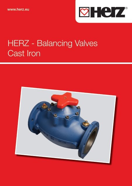
www.herz.eu<strong>HERZ</strong> - <strong>Balancing</strong> <strong>Valves</strong><strong>Cast</strong> <strong>Iron</strong>
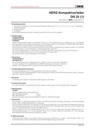
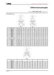
Preset adjustmentergonomic handwheelTripple-O-RingPresetting step isshown on the digitaldisplayTest pointsFull presettingBody made of grey cast iron2
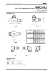
4218 GF STRÖMAX-circuit regulating valve in a flanged version is available in nominalsizes of DN 50 to DN 300. All <strong>HERZ</strong> valves are factory-equipped with testpoints, which can be upgraded with extended test points. The flanged upper partsof <strong>HERZ</strong> 4218 GF STRÖMAX are made of cast iron.The pre-setting marker is fastened as a tag above the valve or pipe. The setting ofthe respective valve is marked by cutting or breaking off the teeth at the figures forfull and partial turns. This permits checking and/or restoration of the original presettingmade on the occasion of the system set-up after servicing without havingto rely on documentation.Presetting1. Set the hand wheel to the desired position (Digital display on handwheel)2. Red numbers are 1/10 of turn, blue numbers are a full turn.3. The presetting spindle is beneath the cover. The spindle can be adjusted with an 8mm screwdriver.To preset turn anti clockwise up to stop. The valve is now able to close and open back to the preset position. Replace the cover on the handwheel.4. The pre-setting marker is fastened as a tag above the valve or pipe. The setting of the respective valve is marked by cutting or breaking off the teethat the figures for full and partial turns. This permits checking and/or restoration of the original pre-setting made on the occasion of system set-upafter servicing without having to rely on documentation.The setting of flowrate is achieved with a measuring device refering to the flow charts. Please see the operating instructions from the measuring device.Minimum operating temperature - 10 °CMaximum operating temperature 110 °CMaximum operating pressure 16 barH2H1DLOrder number 4218 GFStandard characteristic Linear characteristicDN L H1 H2 D kg1 4218 70 1 4218 80 50 230 169 252 150 16,81 4218 71 1 4218 81 65 290 186 279 150 23,61 4218 72 1 4218 82 80 310 208 307 175 301 4218 73 1 4218 83 100 350 235 344 175 -1 4218 74 1 4218 84 125 400 260 385 265 631 4218 75 1 4218 85 150 480 310 450 265 881 4218 76 1 4218 86 200 600 400 569 450 1611 4218 77 1 4218 87 250 730 453 655 450 -1 4218 78 1 4218 88 300 850 520 783 450 3833
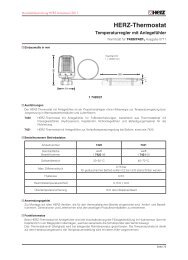
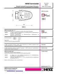
STRÖMAX 4218 GFFunctionTwo test points are fitted on the same side of the valve and factorysealed. This arrangement ensures the best accessibility in any positionand optimum connection of measuring instruments.Field of applicationFor hydraulic balancing in heating or cooling systems for isolatingof manifolds, risers, heat exchangers, heating and cooling systems.<strong>HERZ</strong> STRÖMAX- GF 4218 linearDn 50 65 80 100 125 150 200 250 300kvs 49 75 110 165 241 372 704 812 1383Pos. kv kv kv kv kv kv kv kv kv0,5 0,44 3,7 4,04 7,54 16,72 15,68 4,124 42,13 47,091,0 2,24 5,2 7,79 13,44 26,32 24,98 12,43 61,63 66,491,5 5,24 6,7 11,54 19,34 35,92 34,28 33,195 81,13 85,892,0 8,04 7,97 15,24 25,28 45,55 43,59 53,96 100,65 105,292,5 9,74 9,22 17,24 29,93 53,15 52,04 74,725 117,3 124,693,0 11,46 10,46 19,26 34,61 60,74 60,49 95,49 133,92 144,093,5 12,61 12,96 20,56 37,71 69,09 64,89 116,255 153,82 163,494,0 13,8 15,43 22,86 40,89 77,46 69,31 137,02 173,71 182,954,5 14,8 17,43 24,96 45,29 86,11 77,81 169,12 194,61 212,65,0 16 19,53 27,05 49,65 94,78 86,33 201,22 215,54 242,255,5 17,5 21,03 30,7 54,95 103,73 96,28 233,32 239,14 271,96,0 19,1 22,79 34,39 60,27 112,71 106,26 265,48 262,7 301,576,5 20,95 24,24 39,94 67,47 124,36 118,16 302,38 289,65 323,527,0 22,83 25,49 45,53 74,68 136,05 130,1 339,28 316,64 345,477,5 24,83 27,74 52,68 82,33 152 150,2 376,18 358,24 367,428,0 26,65 30,01 59,85 90,01 167,92 170,26 412,98 399,81 389,298,5 28,35 32,81 66,3 96,96 178,42 193,91 442,38 456,36 455,279,0 30,08 35,6 72,73 103,97 188,92 217,54 471,78 512,88 520,579,5 31,28 38,85 77,38 109,92 200,52 236,74 501,18 554,88 585,8710,0 32,44 42,05 82,07 115,92 212,12 255,9 530,55 596,85 664,1610,5 33,24 44,85 86,07 121,07 220,47 272 545,6 646,65 724,7611,0 34,08 47,66 90,17 126,18 228,85 288,11 560,65 696,48 785,3611,5 34,53 44,66 93,42 130,58 235,75 301,56 575,7 738,53 845,9612,0 34,96 51,63 96,7 134,97 242,65 315,05 590,75 780,57 906,5712,5 54,13 99,05 138,87 249,2 327,65 605,8 813,17 957,7713,0 56,49 101,38 142,74 255,79 340,27 620,86 845,73 1008,9713,5 58,49 104,08 146,74 347,57 634,71 886,63 1060,1714,0 60,77 106,78 150,79 354,84 648,56 927,53 1111,3414,5 62,47 154,54 363,04 662,41 949,88 1174,8915,0 64,21 158,31 371,26 676,33 972,25 1238,4415,5 65,56 161,46 380,41 993 1301,9916,0 66,94 164,59 389,54 1013,7 1365,6316,5 167,04 1039,3 1406,3817,0 169,45 1064,89 14473,1317,5 1073,79 1487,8818,0 1082,72 1528,6718,5 1571,5719,0 1614,4719,5 1657,3720,0 1700,2820,5 1721,4321,0 1742,5821,5 1763,7322,0 1784,914
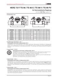
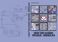
DHBSTRÖMAX 4218 GMFThe differential pressure is measured by an appropriate measuring device and the specific flow rate is determined. All <strong>HERZ</strong>-measuringcomputers directly determine the corresponding flow rate. The flow can be limited by default. The preset value remains the same evenwhen the valve is closed. The presetting is displayed digitally on handwheel.FunctionTwo test points are fitted on the same side of the valve and factorysealed. This arrangement ensures the best accessibility in any positionand optimum connection of measuring instruments.Field of applicationFor hydraulic balancing in heating or cooling systems for isolating ofmanifolds, risers, heat exchan-gers, heating and cooling systems.PresettingThe valve will be delivered in opened position. The pre- setting permits the maximum possible stroke. when the valve is fully closed, the hand wheeldigital display will indicate 0.01. Set the hand wheel to the desired position (Digital display on handwheel).2. Remove the hand wheel securing screw, the handwheel should not be removed.3. The presetting spindle is now accessible, screw in with a screwdriver blade width 3 x 60 until stop position is reached.4. Replace the hand wheel securing screw.5. To mark the adjusted position on the presetting marker and fix it on the valve.The setting of flowrate is achieved with a measuring device refering to the flow charts. Please see the operating instructions from the measuringdevice.Minimum operating temperature - 10 °CMaximum operating temperature 110 °CMaximum operating pressure 16 barD HD FLdLOrder number 4218 GMF DN L H B DH DFL D d1 4218 43 25 160 110 58 71 115 25 141 4218 44 32 180 110 64 71 140 30 191 4218 45 40 200 110 72 71 150 40 191 4218 46 50 230 135 90 110 165 50 191 4218 47 65 290 145 112 110 185 65 191 4218 48 80 310 145 116 110 200 80 191 4218 49 100 350 190 158 190 220 100 191 4218 50 125 400 230 188 190 250 125 191 4218 51 150 480 264 212 190 285 150 235
<strong>HERZ</strong> STRÖMAX 4218 GMFDN 25 32 40 50 65 80 100 125 150kvs 12,2 17,3 28,6 38 60,3 68,5 99,55 186,58 279,05Position kv kv kv kv kv kv kv kv kv0,5 0,35 1,15 1,40 2,70 8,36 11,50 0,00 1,58 8,751,0 0,75 1,90 2,50 7,80 11,56 15,90 12,35 4,36 17,501,5 1,15 2,65 3,60 12,90 14,76 20,30 18,04 10,72 26,082,0 1,90 3,40 4,70 18,60 17,80 24,69 23,74 17,08 34,662,5 4,10 4,15 5,95 22,60 20,15 27,74 29,84 20,27 38,273,0 6,30 4,90 7,20 27,80 22,50 30,60 35,96 23,45 41,883,5 7,70 7,35 9,85 29,30 26,55 36,10 42,56 24,93 44,534,0 9,10 9,80 12,55 31,60 31,60 41,70 49,20 26,41 47,174,5 9,80 12,40 16,05 33,60 38,10 50,70 51,10 28,09 50,345,0 10,50 15,00 19,70 35,50 43,90 60,30 53,00 29,77 53,505,5 10,55 15,80 21,60 37,15 47,40 62,00 57,50 32,57 57,436,0 10,65 16,60 23,50 37,84 51,00 63,78 61,96 35,37 61,366,5 10,70 25,15 53,85 65,88 66,86 38,62 66,147,0 11,50 26,80 56,70 67,80 71,81 41,87 70,927,5 11,53 27,30 58,50 77,11 46,01 76,308,0 11,53 27,80 60,30 82,42 50,14 81,688,5 28,20 87,77 54,94 87,879,0 28,60 93,20 59,74 94,069,5 99,55 65,47 100,5210,0 71,19 106,9810,5 87,53 114,7411,0 85,87 122,5011,5 95,99 132,7212,0 106,10 142,9312,5 117,92 155,8613,0 129,73 168,7913,5 141,12 181,9814,0 152,51 195,1714,5 162,60 207,6915,0 172,69 220,2115,5 179,64 233,0516,0 186,58 245,8816,5 255,7217,0 265,5617,5 272,3118,0 279,05Flow measuring orifice platesFunctionThe orifice plate made of stainless steel PN 16 and has two measuringvalves. The design of the orifice is in accordance with BS 1042,the performance curve characteristics are according to BS 7350.cField of application<strong>HERZ</strong> orifice plates are installed in the circuits of the hot water centralheating and cooling systems, and ensure the balance of the hydrauliccircuits.The orifice plates are used either in a supply or in a return pipe.They are either closely coupled with a balancing valve <strong>HERZ</strong> to forma complete set or used in connection with an isolation valve <strong>HERZ</strong>.The balancing is accomplished by setting the control valve during themeasurements of the pressure drop at orifice.Maximum operating temperature 110 °CMaximum operating pressure 16 barAøBBenefits :– Ease of use because of the use of only one characteristic of theorifice plate.– Can be installed separately, e.g. as a fixed orifice.Order numberOrifice plateDN A B C kv kg1 4000 07 65 20 158 160 100,7 1,91 4000 08 80 20 166 170 133,8 2,21 4000 09 100 20 164 176 237,7 2,71 4000 10 125 20 194 191 339 3,21 4000 11 150 20 220 204 511 3,81 4000 12 200 20 275 232 858 5,51 4000 13 250 20 331 258 1235 7,01 4000 14 300 20 386 287 1793 10,0c6
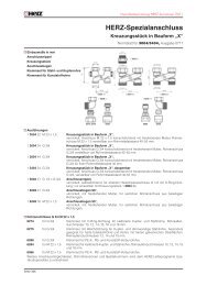
<strong>HERZ</strong>- Flow chartsArt. Nr. 1 4218 80 Dim. DN 50STRÖMAX 4218 GF<strong>HERZ</strong>- Flow chartsArt. Nr. 1 4218 81 Dim. DN 65STRÖMAX 4218 GFk v0,010,1101001000k v910 100 100012341 728394105116125678101112131415161<strong>HERZ</strong>- Flow charts STRÖMAX 4218 GFArt. Nr. 1 4218 82 Dim. DN 80[kg/h]Flowrate qm[l/sec] 0,1 1 10 100<strong>HERZ</strong>- Flow charts STRÖMAX 4218 GFArt. Nr. 1 4218 83 Dim. DN 100k v12345687 91011121314k v1234567891011121314151617[kPa][mbar][kPa][mbar]∆p∆p[kPa][mbar]∆p∆p[kg/h]Flowrate qm[l/sec] 0,01 0,1 1 10[kPa][mbar]subject to changesubject to change[kg/h]Flowrate qm[l/sec] 0,1 1 10 100subject to change[kg/h]Flowrate qm[l/sec] 0,1 1 10 100subject to change7
<strong>HERZ</strong>- Flow chartsArt. Nr. 1 4218 84 Dim. DN 125STRÖMAX 4218 GF<strong>HERZ</strong>- Flow chartsArt. Nr. 1 4218 85 Dim. DN 150STRÖMAX 4218 GFk v123456k v12345678789101112910111213141516[kPa][mbar]<strong>HERZ</strong>- Flow charts STRÖMAX 4218 GFArt. Nr. 1 4218 86 Dim. DN 200<strong>HERZ</strong>- Flow charts STRÖMAX 4218 GFArt. Nr. 1 4218 87 Dim. DN 250k v2468101214101112131415161718k v123456789[kPa][mbar][kPa][mbar]∆p∆p∆p∆p[kg/h]Flowrate qm[l/sec] 0,1 1 10 100subject to change[kPa][mbar][kg/h]Flowrate qm[l/sec] 0,1 1 10 100subject to change[kg/h]Flowrate qm[l/sec] 0,1 1 10 100subject to change[kg/h]Flowrate qm[l/sec]1 10 100 1000subject to change8
5151<strong>HERZ</strong>- Flow chartsArt. Nr. 1 4218 88 Dim. DN 300STRÖMAX 4218 GF<strong>HERZ</strong>- Flow charts4000 FOrifice plates∆p[kPa]k v24[kg/h]Flowrate qm[l/sec]68101214161820221 10 100 1000[mbar]subject to changekv1005 10001 10 100005000 500 50 1000100[mbar][kPa]505001001050100,5∆p0,1[kg/h]100.0005.000 1.000.0001.00010.000 10.000.00050.000 500.000 5.000.000 Flowrate[l/sec]1 10 100 1000subject to changeOrdernumberTest point adaptors 1 0284 00Test point extention1 Set = 2 PcsTest points for <strong>HERZ</strong>-STRÖMAX-Circuit regulatingvalves (manufactured from 2004), brass version, blue cap (return) for flow computer.Test points for <strong>HERZ</strong>-STRÖMAX-Circuit regulatingvalves (manufactured from 2004), brass version, red cap (flow) for flow computer.Test points for <strong>HERZ</strong>-STRÖMAXCircuitregulating valves BrassExtended model for insulated valves up to 40mmversion, blue cap (return) for flow computer.Test points for <strong>HERZ</strong>-STRÖMAXCircuitregulating valves. Brass version, red cap (flow) for flow computer.Extended model for insulated valves up to 40 mm.Test points with draining functionBrass version, red cap (flow).Test points with draining functionBrass version, blue cap (return).1/4 1 0284 101/4 1 0284 011/4 1 0284 021/4 1 0284 111/4 1 0284 121/4 1 0284 221/4 1 0284 21Test points long version with draining function, blue cap 1/4 1 0284 23Test points long version with draining function, red cap 1/4 1 0284 24Presetting markerPlastic tag for marking the presetting step.Can be mounted on the valve or pipe.Test points with pulse pipe connectionbrass version, blue cap (return) for flow computer.Test points with pulse pipe connectionbrass version, red cap (flow) for flow computer.1 6517 051/4 1 0284 031/4 1 0284 039
LGHKM/nLever dimensionsDN a bF50 195 60C65 195 6080 195 60EA100 240 65125 240 65B150 390 70200 390 70DFor the dimensions DN250 and DN 300 handwheelwith worm gear is usedDN Type BA Type BB A B C D E~ kgType BA~ kgType BB ISO F G H K L50 1 4219 01 1 4219 11 48 94 43 68 125 3,2 3,6 F05 13 34 11 70 8865 1 4219 02 1 4219 12 62 112 46 80,5 149 3,6 4,5 F05 12,5 34 11 70 8880 1 4219 03 1 4219 13 76,7 131 46 88 158 4,2 5,8 F05 12,5 34 11 70 88100 1 4219 04 1 4219 14 95 150 52 102 182 5,7 7,4 F07 15 34 14 70 88125 1 4219 05 1 4219 15 118,6 179 56 127 201 7,6 9,5 F07 15 34 14 70 88150 1 4219 06 1 4219 16 143,6 205 56 132 214 9,2 12 F07 15 34 14 70 88200 1 4219 07 1 4219 17 193,6 262 60 145 245 14 19,3 F07 18 16 14 70 88250 1 4219 08 1 4219 18 243,6 316 68 191 283 23,6 31,5 F10 20 16 17 102 130300 1 4219 09 1 4219 19 293,6 366 78 216 308 32,1 41,8 F10 20 16 17 102 130Minimum operating temperature - 20 °CMaximum operating temperature 110 °CMaximum operating pressure (DN 50 - 200) 16 bar (for water)Maximum operating pressure (DN 250 - 300) 10 bar (for water)<strong>HERZ</strong> butterfly valves are available in sizes of 50 to 300. The flow can be limited by default.The default settings are indicated by the position of the lever.FunctionThe butterfly valves can be used as isolating and regulating valves, which is achieved by the lever locking in the notch plate. The lever is made of fiberglassreinforcedpolyamide with spring-activated locking mechanism and integrated locking hole.The top flange is made for the standard gears and actuating drives according to an ISO 5211.The rubber liner protects the body against internal corrosion. No additional seals are required.After final mounting the body of the butterfly valve is tested on body strength, body leakage, seat tightness and functionality according to an ISO 5208.Field of applicationSuitable for water and air systems in heating, cooling, air conditioning and ventilation.The butterfly valves have the body typesType “ZF, WT” GG, JL 1040, according to EN 1561Type “AF, LT ‘: GGG, JS1030, according to EN 1563.The body has blue color (RAL 5000),Inside the body is a rubber liner made of EPDM in accordance with anISO 1691, the disc is made of carbon steel, covered with nickel and thedrive shaft spit into 2 parts is made of Stainless Steel 1.4408 accordingto EN 10088. The valves are available in Semi-lugged (type ZF, WT) orFully-lugged (type AF, LF) versions.Type ZF, WTType AF, LT10
12Handwheel with a worm gear and actuating drivesDNTypeConnection according toISO 5211A B C ~kg50 - 80 WK 1 F05 100 104 21 1100 - 200 WK 2 F07 125 118 29 2250 - 300 WK 3 F10 315 203 37 3Actuating drives (BELIMO)for <strong>HERZ</strong> baterfly valvesDNDim.Necessary force,NmSlower actuator,150 sFaster actuator(15...25 s)6 bar 10 bar 16 bar 6 bar 10 bar 16 bar 6 bar 10 bar 16 bar50 2" 12 13 1365 2,5" 18 18 20SM230A, AF23080 3" 25 26 28 GM230A100 4" 39 41 44 GM230A125 5" 65 69 76SY1-230-3-TSY2-230-3-T150 6" 91 97 110 SY3-230-3-T200 8" 180 190 210 SY4-230-3-T250 10" 275 315 SY4-230-3-T300 12" 390 440 SY4-230-3-T SY5-230-3-TMounting schemeElectrical connection5mmLS3 LS4A B C D E FF3Y U5 C1 C2TTS1 S2T~Y2 Y1kv-value depending on the lever positionDN 300DN 250DN 300DN 200DN 150DN Dim. kv zeta50 2" 91 m 3 /h 1,1865 2,5" 206 m 3 /h 0,6680 3" 436 m 3 /h 0,34100 4" 660 m 3 /h 0,36kv in m 3 /hDN 100DN 80DN 65DN 50125 5" 1300 m 3 /h 0,22150 6" 2100 m 3 /h 0,18200 8" 4100 m 3 /h 0,15250 10" 6090 m 3 /h 0,17300 12" 9570 m 3 /h 0,14Position of the grid11
<strong>HERZ</strong> <strong>Valves</strong> UKProgress House, Moorfield PointMoorfield Road, Slyfield Industrial EstateGuildford, Surrey GU1 1RUTelephone: +44 (0)1483 502211, Fax: +44 (0)1483 502025E-Mail: sales@herzvalves.comwww.herzvalves.com4218 STRV-EN-0312-1<strong>HERZ</strong> Armaturen GmbHRichard-Strauss-Str. 22, A-1230 ViennaTel.: +43 (0)1 616 26 31-0, Fax: +43 (0)1 616 26 31-27E-Mail: office@herz.euwww.herz.eu