ASSEMBLY SHEET FOR THE GTP CONVERSION KIT - Ofna
ASSEMBLY SHEET FOR THE GTP CONVERSION KIT - Ofna
ASSEMBLY SHEET FOR THE GTP CONVERSION KIT - Ofna

Create successful ePaper yourself
Turn your PDF publications into a flip-book with our unique Google optimized e-Paper software.
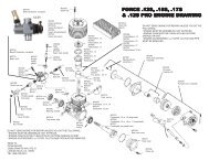
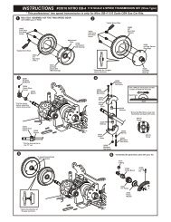
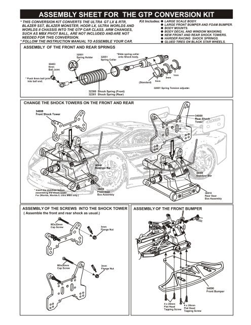
<strong>ASSEMBLY</strong> <strong>SHEET</strong> <strong>FOR</strong> <strong>THE</strong> <strong>GTP</strong> <strong>CONVERSION</strong> <strong>KIT</strong>* THIS <strong>CONVERSION</strong> <strong>KIT</strong> CONVERTS <strong>THE</strong> ULTRA GT LX & RTR,BLAZER SST, BLAZER MONSTER, HODR LX, ULTRA WORLDS ANDWORLDS II CHASSIS INTO <strong>THE</strong> <strong>GTP</strong> CAR CLASS. ARM CHANGES,SUCH AS MBX PIVOT BALL, ARE NOT INCLUDED AND ARE NOTNEEDED <strong>FOR</strong> THIS <strong>CONVERSION</strong>.* FOLLOW <strong>THE</strong> INSTRUCTION MANUAL TO ASSEMBLE YOUR CAR.<strong>ASSEMBLY</strong> OF <strong>THE</strong> FRONT AND REAR SPRINGSKit Includes:LARGE SCALE BODY.LARGE FRONT BUMPER AND FOAM BUMPER.BODY MOUNTS.BODY DECAL AND WINDOW MASKING.NEW FRONT AND REAR SHOCK TOWERS.HARDER RACING SHOCK SPRINGS.GLUED TIRES ON BLACK STAR WHEELS.304036mmBall Joint32051Spring Holder*Slide spring collar32051 onto Shock body.Spring Collar* Push 6mm ball jointinto ball end.(Standard)5mm3mm1mm32300 Shock Spring (Front)32301 Shock Spring (Rear)32051 Spring Tension adjust er.CHANGE <strong>THE</strong> SHOCK TOWERS ON <strong>THE</strong> FRONT AND REAR34008Front Shock Tower34009Rear ShockTower30340Stabilizer Bar30340Stabilizer Bar10* Insert the stabilizer beforeassembling the shock towerFor (Worlds, Worlds II, Ultra MBX only.)30010Front GearBox Assembly30010Rear GearBox Assembly<strong>ASSEMBLY</strong> OF <strong>THE</strong> SCREWS INTO <strong>THE</strong> SHOCK TOWER( Assemble the front and rear shock as usual.)<strong>ASSEMBLY</strong> OF <strong>THE</strong> FRONT BUMPERM3x20mmCap ScrewScrewCement3mmFlange Nut10M3x20mmCap ScrewScrewCement3mmFlange Nut34090Front Bumper4 x 20mmFlat HeadTapping Screw4 x 20mmFlat HeadTapping Screw
For Hodr,. Blazer SST.,Blazer Monster, optionFor"Ultra GT LX", option366907mm PlasticArm Ball End366907mm PlasticArm Ball End368805x60mmTurnbuckle368805x60mmTurnbuckle368507mm Ball368507mm Ball* Builds two upper arms for leftand right hand-side.* Builds two upper arms for leftand right hand-side.<strong>ASSEMBLY</strong> OF <strong>THE</strong> UPPER ARM ONTO <strong>THE</strong> GEAR BOXM3NylonLock NutAssembly of the right and left hand sideare the same.3 x 15mm Screw* Insert into rear hub.4mmPlastic WasherM3NylonLock Nut* Insert 30320 drive shaftbefore installing arms.3 x 15mmScrew3 x 25mmCap Screw<strong>ASSEMBLY</strong> OF <strong>THE</strong> STABILIZER ROD304016mmStabilizerBall End304023 X 30mmTie Rod304016mmStabilizerBall End3 x 3mmSet Screw303406mmStabilizerBall End3 x 15mmScrew304036mmBall Joint15mm0 10 20 30 40 50mm
<strong>ASSEMBLY</strong> OF <strong>THE</strong> REAR BODY MOUNT3mmNylon Nut33010Body MountRearBody Post2mmNut2x18mmScrew3 x 15mmScrew3 x 15mmScrew<strong>ASSEMBLY</strong> OF <strong>THE</strong> REAR BODY SUPPORT33011Body Supporter31149Clips33011Body Post Set31149Clips* Use this body postfor rear.
<strong>ASSEMBLY</strong> OF <strong>THE</strong> TIRES AND WHEELS86059Inner Sponge(Small)* Take offdouble side tapebacking.86049Chrome Wheel86048Black Wheel* Stick the sponge to the middleof the wheel.86044 - Red86045 - White86046 - Lime86087 - Yellow86048 - Black86049 - Chrome17mm 5-star wheels,Two (2) pairs per bag.86032 - Orange86033 - Chrome86034 - White86035 - Yellow86036 - Lime86037 - L.Gray86038 - D.Gray86039 - Red17mm Dual Spokewheels, Two (2) pairsper bag.86059Inner Sponge(Large)86050 - Slick Tire, No-Belt86051 - Slick Tire, Belted86052 - Street Tire, No-Belt86053 - Street Tire, Belted* Use cementto glued together.* The tires might be differentas picture shown here.86050Slick Tires* Insert sponge into thetire as shown.*Insert the tire intothe grooves of thewheel.86504 - Pre-Glued Set, Slick86505 - Pre-Glued Set, StreetPre-glued set use 86045 wheelsINSTANTGLUE* Apply instant glue intothe grooves of the wheel.INSTANTGLUERear Hub Assembly30051Wheel NutRFront Knuckle ArmAssembly30051Wheel Nut
SET-UPADJUSTMENT OF <strong>THE</strong> CHASSISRIDE HEIGHT CLEARANCEUse 2mm hex wrench toadjust 4x10mm set screwin the front lower arm.(FRONT)Use 2mm hex wrench toadjust the 4x10mm setscrew in the rearlower arm.(REAR)Place the model car on a flat surface.Use a 2mm hex wrench to adjustmentthe chassis to it's minimum clearance.We Suggest: 10mm in front and rear.Adjust the right and left-handsideto the same height.SET-UP OF <strong>THE</strong> FRONT WIDTH* Use a 2.5mm hex wrench toadjust the length of the steeringballs. This will make thefront wider or narrower.Adjust thesteering balls.(FRONT)ADJUSTMENT OF <strong>THE</strong> FRONT AND REAR CAMBER(Positive) +Adjust the uppersteering ball toadjust the camber.0- (Negative)(FRONT)154mmCenterFRONT TOE-IN AND TOE-OUT SETTINGSThe rear camber adjustment can bemade by rotating the turnbuckle rodon the upper arms, clockwise oranticlockwise.Toe-Out0Toe-In(Positive) +0- (Negative)(REAR)Adjust the length of the frontsteering rod to change the toeangle.Making the steering rod longerwill make the front tires becometoe-in. The Response will beslower.Making the steering rod shorterwill make the front tires becametor-out. The Response will bequicker.Steering Rod