Manual - Mark Climate
Manual - Mark Climate
Manual - Mark Climate

Create successful ePaper yourself
Turn your PDF publications into a flip-book with our unique Google optimized e-Paper software.
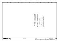
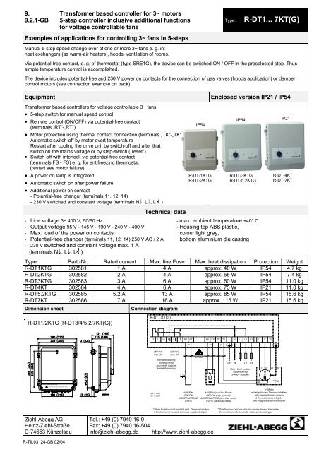
Vor Öffnen des Deckels Gerät spannungsfrei schalten!Sw itch off the m ain supply before rem oving the cover!9.9.2.1-GBTransformer based controller for 3~ motors5-step controller inclusive additional functionsfor voltage controllable fansExamples of applications for controlling 3~ fans in 5-steps<strong>Manual</strong> 5-step speed change-over of one or more 3~ fans e. g. in:heat exchangers (as warm-air heaters), hoods, ventilation of rooms.Type:R-DT1... 7KT(G)Via potential-free contact, e. g. of thermostat (type SRE1G), the device can be switched ON / OFF in the preselected step. Thussimple temperature control is accomplished.The device includes potential-free and 230 V power on contacts for the connection of gas valves (hoods application) or dampercontrol motors (see connection example on back).EquipmentTransformer based controllers for voltage controllable 3~ fans• 5-step switch for manual speed control• Remote control (ON/OFF) via potential-free contact(terminals „RT”-„RT”).• Motor protection using thermal contact connection (terminals „TK"-„TK").Automatic switch-off by motor overt temperatureRestart after cooling the drive unit by switch-off and after thatswitch on the mains voltage or by step-switch („reset").• Switch-off with interlock via potential-free contact(terminals FS - FS) e. g. for antifreezing thermostat(restart see motor failure)• A power on lamp is integrated• Automatic switch on after power failure• Additional power on contact- Potential-free changer (terminals 11, 12, 14)- 230 V switched and constant voltage (terminals N↓, L↓, L )- Line voltage 3~ 400 V, 50/60 Hz- Output voltage 95 V - 145 V - 190 V - 240 V - 400 V- Max. load of the power on contacts:- Potential-free changer (terminals 11, 12, 14) 250 V AC / 2 A- 230 V switched and constant voltage max. 1 A(terminals N↓, L↓, L )Technical dataEnclosed version IP21 / IP54- max. ambient temperature +40° C- Housing top ABS plastic,colour light grey,bottom aluminium die castingType Part.-Nr. Rated current Max. line Fuse Max. heat dissipation Protection WeightR-DT1KTG 302581 1 A 4 A approx. 40 W IP54 4.7 kgR-DT2KTG 302582 2 A 4 A approx. 55 W IP54 7.4 kgR-DT3KTG 302583 3 A 6 A approx. 60 W IP54 11.0 kgR-DT4KT 302584 4 A 6 A approx. 75 W IP21 11.0 kgR-DT5.2KTG 302585 5.2 A 13 A approx. 85 W IP54 15.6 kgR-DT7KT 302586 7 A 16 A approx. 115 W IP21 15.6 kgDimension sheetConnection diagramIP54R-DT-1KTGR-DT-2KTGIP54R-DT-3KTGR-DT-5.2KTGIP21R-DT-4KTR-DT-7KTR-DT1/2KTG (R-DT3/4/5.2/7KT(G))R-DT...KT(G)12 11 14 N L L RT RT FS FS TK TK1* 1* 1*N L1 L2 L3U V W250VACmax. 2A230VACmax. 1AKontaktbelastungcontact ratingpouvoir de coupurekontaktbelastning0 1230V ACJPENL1L2Netz / line / secteurNätanslutning3~400V 50/60HzL3UVM3~WPETKTKbzw.Y or DSR171K0524.11.2004AUS/EINOFF/ONARRET/MARCHEAV/PÅAUS/EIN (nur über Reset)OFF/ON (only by reset)ARRET/MARCHE (lors d´un reset)AV/PÅ (bara över reset)3~ Motormit eingebauten Thermokontaktenwith internal thermocontactsà thermocontacts intégrésmed integrerade termokontakterZiehl-Abegg AGHeinz-Ziehl-StraßeD-74653 Künzelsau1* Wenn Funktion nicht benötigt wird, Klemmen brücken 1* Si la fonction n’est pas utile, les bornes doivent être reliéesIf function is not needed, terminals must be bridged Om funktionen inte används, måste plintarna byglasTel.: +49 (0) 7940 16-0Fax: +49 (0) 7940 16-504info@ziehl-abegg.de http://www.ziehl-abegg.deR-TIL03_24-GB 02/04
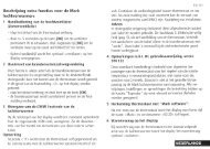
Connection example for damper control motorsConnection of damper control motors (different models) is possible via the potential-free contacts orvia the 230 V contacts of the power on relay. This relay rises, if the device is activated and the fan isrunning. By switching off via remote control (terminals „RT”-„RT“) or in case of motor fault the relayfalls off.For damper control motors with „single-wire-control” connection with constant voltage (also in switchposition „0”) for „damper CLOSE”.For motors with „single-wirecontrol”- damper „OPEN”: if fan is running,230 V at terminal L- damper „CLOSE”: constant voltageat terminal L, if fan is not running(also in switch position ”0”)For motors with „spring return”- damper „OPEN”: if fan is running,230 V at terminal L- damper „CLOSE”: via spring return(if no voltage at L )For motors with „2-wire-control”- damper „OPEN”: if fan is running,voltage at terminal 14- damper „CLOSE”: voltage atterminal 12, fan is not running(also in switch position ”0”)AC 230 VAC 230 VNLLNLLN 11 12 14AC 24 V...250 VMMMR-TIL03_24-GB 02/04