
Create successful ePaper yourself
Turn your PDF publications into a flip-book with our unique Google optimized e-Paper software.
<strong>Palax</strong>_KS_35_<strong>Ergo</strong>+S_v4_07_EN.doc2
31 FOREWORD........................................................................................................................................................... 51.1 EU DECLARATION OF CONFORMITY ..................................................................................................................... 51.2 INTENDED USE OF THE MACHINE ........................................................................................................................... 61.3 MARKINGS AFFIXED TO THE MACHINE .................................................................................................................. 61.4 NAMEPLATES ........................................................................................................................................................ 61.5 SAFETY INSTRUCTIONS.......................................................................................................................................... 61.6 NOISE EMISSION AND VIBRATION .......................................................................................................................... 71.7 RESPONSIBILITIES OF THE OPERATOR .................................................................................................................... 71.8 OPERATING CONDITIONS....................................................................................................................................... 71.9 MACHINE MODELS ................................................................................................................................................ 81.10 TERMS OF WARRANTY...................................................................................................................................... 82 TAKING DELIVERY AND ASSEMBLY OF THE MACHINE........................................................................ 82.1 STATE OF DELIVERY AND ACCEPTANCE CONTROL................................................................................................. 82.2 LIFTING AND TRANSFERRING THE MACHINE, FIG. 3, ALL MODELS ........................................................................ 92.3 MAIN PARTS OF THE MACHINE, FIG 4 .................................................................................................................... 92.4 MAIN PARTS OF THE MACHINE, S MODEL, FIG. 5 ................................................................................................. 92.5 MAIN PARTS, FIG. 6, ALL MODELS ...................................................................................................................... 102.6 MAIN PARTS, FIG. 7, ALL MODELS ...................................................................................................................... 102.7 TOPPING UP HYDRAULIC OIL, FIG. 7, ALL MODELS.............................................................................................. 102.8 TOPPING UP CHAIN-SAW OIL, FIG. 7, ALL MODELS .............................................................................................. 102.9 INSTALLING THE ADJUSTMENT LEVER FOR THE SPLITTING WEDGE, FIG. 8, ERGO MODEL .................................. 102.10 INSTALLING THE ADJUSTMENT LEVER FOR THE CROSSCUT SAW-BAR, FIG. 8B, ERGO MODEL........................ 102.11 BRINGING THE CONVEYOR INTO THE WORK POSITION, FIGS. 9 AND 10........................................................... 112.12 BRINGING THE CONVEYOR INTO THE TRANSPORT POSITION, FIG. 9 AND 10 ................................................... 113 OPERATING THE PALAX KS 35 FIREWOOD PROCESSOR .................................................................... 113.1 TRANSMISSION.................................................................................................................................................... 113.2 OPERATING THE PALAX 35 ERGO MODEL USING THE MECHANICAL CONTROL, FIG. 11....................................... 123.3 OPERATING THE PALAX KS 35 S MODEL, FULL-HYDRAULIC CONTROL, FIG. 12................................................. 123.4 LUBRICATING THE CHAIN-SAW, FIG. 13, ALL MODELS ........................................................................................ 133.5 ADJUSTING THE OIL VOLUME, ALL MODELS ........................................................................................................ 133.6 CHECKING THE OIL LEVEL, FIG. 13B ................................................................................................................... 133.7 INFEED CONVEYOR, FIG. 14 AND 15, ALL MODELS.............................................................................................. 143.8 DISCHARGE CONVEYOR, FIG 16 .......................................................................................................................... 143.9 ALL TRACTOR-DRIVEN MODELS .......................................................................................................................... 153.10 ALL ELECTRICALLY DRIVEN MODELS ............................................................................................................. 153.11 HEATING THE OIL OF AN ELECTRICALLY DRIVEN MACHINE, ALL MODELS ...................................................... 153.12 HEATER CARPET FOR HYDRAULIC TANK, FIG. 17 ........................................................................................... 164 USING THE FIREWOOD PROCESSOR, CROSSCUT OPERATION, ALL MODELS............................. 164.1 PREPARATIONS BEFORE THE USE OF THE MACHINE, ALL MODELS........................................................................ 164.2 CHECKING THE CHAIN-SAW LUBRICATOR............................................................................................................ 164.3 CHAIN-SAW......................................................................................................................................................... 174.4 DURING THE OPERATION ..................................................................................................................................... 174.5 CROSSCUT OPERATION ........................................................................................................................................ 174.6 DISTURBANCES DURING CROSSCUT OPERATION AND THEIR REMEDY .................................................................. 174.7 CROOKED TREES ................................................................................................................................................. 174.8 BIG TREES ........................................................................................................................................................... 174.9 CUTTING SMALL TREES ....................................................................................................................................... 175 USE OF THE FIREWOOD PROCESSOR, SPLITTING OPERATION........................................................ 175.1 SPLITTING CYLINDER .......................................................................................................................................... 175.2 HIGH-SPEED VALVE WITH AUTOMATIC OPERATION, FIG. 20 ............................................................................... 185.3 SPLITTING WEDGES SHORT, STRAIGHT WEDGE, OPTIONAL.................................................................................. 185.4 MANUAL ADJUSTMENT OF THE SPLITTING WEDGE, FIGURE 22........................................................................... 185.5 HYDRAULIC ADJUSTMENT OF THE SPLITTING WEDGE, S MODEL, FIG. 23 ............................................................ 195.6 ADJUSTING THE SPEED OF THE SPLITTING WEDGE ADJUSTMENT CYLINDER, FIGURE 24 ...................................... 195.7 DISTURBANCES DURING THE SPLITTING OPERATION AND THEIR REMEDY ........................................................... 195.8 STUCK WOOD ...................................................................................................................................................... 195.9 RE-SPLITTING THE LOGS SAFELY......................................................................................................................... 19<strong>Palax</strong>_KS_35_<strong>Ergo</strong>+S_v4_07_EN.doc
46 HOW THE SAFETY DEVICES AFFECT THE OPERATION OF THE MACHINE, ALL MODELS...... 206.1 PROTECTIVE NET FOR SPLITTING CHUTE A, FIG. 25............................................................................................. 206.2 ACTIVE WOOD CLAMP B, FIG. 25 ........................................................................................................................ 206.3 SPRING-LOADED LOG-CLAMP, FIG. 26................................................................................................................. 206.4 LOG-CLAMP WITH HYDRAULIC CYLINDER, FIG. 27.............................................................................................. 207 OPERATION OF CUTTING, SPLITTING AND THE INFEED CONVEYOR, ERGO MODEL .............. 217.1 DENOMINATION OF PARTS, ERGO MODEL, FIG. 28 .............................................................................................. 217.2 OPERATING PRINCIPLE OF CUTTING, SPLITTING AND THE INFEED CONVEYOR, ERGO MODEL .............................. 217.3 CUTTING ............................................................................................................................................................. 217.4 SPLITTING ........................................................................................................................................................... 217.5 FEEDING THE TREE .............................................................................................................................................. 217.6 HAND-START AND STOPPING OF THE SPLITTING OPERATION................................................................................ 218 OPERATION OF CUTTING, SPLITTING AND THE INFEED CONVEYOR, S MODEL........................ 228.1 DENOMINATION OF PARTS, S MODEL, FIG. 30..................................................................................................... 228.2 OPERATION OF JOYSTICK-VALVE, S MODEL, FIG. 31 .......................................................................................... 228.3 CUTTING ............................................................................................................................................................. 228.4 SPLITTING ........................................................................................................................................................... 228.5 FEEDING THE TREE .............................................................................................................................................. 229 MAINTENANCE OF THE MACHINE.............................................................................................................. 239.1 OPENING THE PROTECTIVE STRUCTURES, OBJECTS, FIG. 32 ................................................................................ 239.2 COVERS THAT NEED TO BE OPENED FOR MAINTENANCE WORK ON THE SAW-BAR, FIGS. 32 AND 33. .................. 239.3 COVERS THAT NEED TO BE OPENED FOR MAINTENANCE WORK ON THE HYDRAULIC SYSTEM, FIG. 32 AND 34. . 239.4 CHANGING THE GEARBOX OIL ............................................................................................................................. 239.5 CHANGING THE HYDRAULIC OIL AND THE FILTER, FIG. 35 .................................................................................. 249.6 SERVICING THE VALVE, FIG. 36 .......................................................................................................................... 249.7 DETENT END OF THE VALVE, FIG. 37................................................................................................................... 249.8 LUBRICATING THE SPOOL SHIFTER, FIG. 38......................................................................................................... 249.9 STRUCTURE OF THE DETENT END AND THE CORRECT ORDER OF PARTS, FIG. 39.................................................. 259.10 INITIAL SETTINGS OF THE VALVE.................................................................................................................... 259.11 CHANGING THE SAW-CHAIN ........................................................................................................................... 259.12 OPENING THE SAW-BAR COVER, SEE POINT 9.2............................................................................................... 259.13 CHANGING THE SAW-CHAIN, FIG. 40.............................................................................................................. 269.14 SHARPENING THE CHAIN IN THE MACHINE, FIG. 40B ...................................................................................... 269.15 SHARPENING THE CHAIN IN A VICE, FIGS. 41 AND 42 ..................................................................................... 269.16 CONVEYOR CHAINS, FIG. 43........................................................................................................................... 279.17 BEARINGS AT THE LOWER END OF THE CONVEYOR, FIG. 44 ........................................................................... 279.17 CLEANING THE MACHINE................................................................................................................................279.18 WASHING THE MACHINE................................................................................................................................. 279.19 STORING THE MACHINE. ................................................................................................................................. 2710 MAINTENANCE SCHEDULE ........................................................................................................................... 2811 MALFUNCTIONS AND THEIR REMEDY..................................................................................................... 2812 ELECTRIC DIAGRAMS..................................................................................................................................... 29<strong>Palax</strong>_KS_35_<strong>Ergo</strong>+S_v4_07_EN.doc
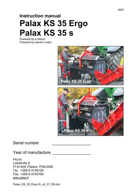
51 ForewordCongratulations for purchasing your new PALAX Firewood Processor.The uncompromised aim in the development of this machine has always been high quality,reliability of operation and safety.We believe that you will be satisfied with this firewood processor which meets all theessential safety regulations issued by the EU. As a proof of this the CE-sign has beenaffixed to the machine and the EU Declaration of Conformity accompanied by theOperator´s manual will follow the machine.Ylistaron Terästakomo Oy1.1 EU Declaration of ConformityManufacturer: Ylistaron Terästakomo OyLahdentie 9FI-61400 YlistaroFinlandProduct:<strong>Palax</strong> KS 35 <strong>Ergo</strong> is a Firewood Processor equipped with a chain-saw andmechanical control.<strong>Palax</strong> KS 35 s is a Firewood Processor equipped with a chain-saw and fullhydrauliccontrol.The machines feature a 4,3-m swinging discharge conveyor.Powered by:Tractor P.T.O. or electric motorModels: KS 35 TR Powered by tractor equipped with own hydraulic systemKS 35 SM Powered by electric motorThe following standards and instructions have been applied in manufacturing the machine.SFS-EN 292-2+A1 Safety of machinery. Basic concepts, general principles for designEN 609-1Log splittersEN 620Continuous handling equipment and systemsEN 1553Power- take-off shaftsEN 1870-6 Circular sawing machinesSFS-EN 60204-1 Electrical equipment of machinesSFS-EN ISO 14982 Electro-magnetic combatibilitySFS-ISO 11684 Safety signs and hazard pictorialsSFS-handbook 93 Safety of machinesEN 982HydraulicsType approvalBLB-2007/002Ylistaron Terästakomo OyMartti VaurioManaging Director<strong>Palax</strong>_KS_35_<strong>Ergo</strong>+S_v4_07_EN.doc
1.2 Intended use of the machineThis Firewood Processor with Conveyor is intended to be used for production of firewoodfrom round timber.Use of the machine for any other purposes is prohibited.Maximum size of the wood: For cutting, the maximum diameter of the tree is about 35 cm. The maximum length of the log is 4-5 m. When handling long trees, we recommend using a specific log-lifting deck with rollersor hydraulic feed.1.3 Markings affixed to the machineBeware the saw-barRead the instruction manualAlways use eye guards and hearing protectors<strong>Manual</strong> start of the splitting cylinderHydraulic height adjustment of the splitting wedge, optionalSpeed of the power take-off shaftDanger zone around the conveyor1.4 NameplatesNameplate on the machine The name and address of the manufacturer Designation of the machine type Serial number and year of manufacture Total weight of the machine Length of the saw-bar Max. hydraulic pressure The nameplate is affixed onto the side of the top-link bracket housing.Nameplates on the electric drive 3-phase motor Voltage 230 / 380 V or 380 / 600 V, may vary depending on the country. Output 7.5 kW.1.5 Safety instructions Always use eye guards and hearing protectors. Do not wear loosely-fitting clothing. Keep the working space clean and clear of foreign objects. Never use the machine indoors, risk of dust generation! Only operate the machine in an adequately lit space. Make sure that all other people stay outside the operating range. The machine isintended for operation by one person only. The machine is exclusively intended for the production of firewood. Exercise particular caution when cutting knotty or crooked trees, because, as a resultof faulty cutting, the tree might roll over or twist the saw-bar. Carelessness during the cut-off operation constitutes a serious danger. Always stop the machine before servicing. Always ensure that the electric conductors, if any, are intact. Never remove any safety-related devices from the machine. Remember that you areresponsible for any injuries caused if safety-related devices have been removed fromthe machine. Always carry out the required preparations before starting the operation.6<strong>Palax</strong>_KS_35_<strong>Ergo</strong>+S_v4_07_EN.doc
7Only use fault-free power take-off drive shafts and attach the chains for the shaft-guardto the machine.The danger zone around the conveyor: 5 metres to both sides and to the rear.Never use a timber loader for loading the infeed conveyor.WARNING!Beware of low bridges and other obstacles!The width of the machine equipped with the 4,3-m conveyor is about 2,84 m. This meansthat, depending on the size of the tractor, the transport width of the conveyor may extendoutside the rear wheel on the right-hand side.1.6 Noise emission and vibrationThe chain-saw is a relatively low-noise machine.If you are using a tractor with only one power-take-off-shaft speed, the loudest noisecomes from the tractor.The machine does not cause harmful vibrations.1.7 Responsibilities of the operator The machine may only be used to produce firewood. All the safety-related devices are necessary to ensure a sufficient level of safety. The PALAX is a very safe machine provided that the instructions supplied are properlyfollowed, the regular maintenance routines are duly executed and the work is carriedout without haste. The machine operator is responsible for the flawless operation of the safety-relateddevices and for ensuring that the machine is serviced in a due manner. The operator is responsible for ensuring that no one else is subjected to any danger. Modifying the construction of the machine is prohibited. Remember that as the operator you are responsible for any injuries caused if safetyrelateddevices have been removed from the machine.1.8 Operating conditions Never use the machine indoors, owing to the risk of dust generation or the danger ofexhaust gases for a unit powered by a combustion engine. Only operate the machine in an adequately lit space. Make sure that no other people, especially children, are present inside the operatingrange. Never use a timber loader for loading the infeed conveyor. It is recommended that a suitable stand be purchased or made that enables the treesto be processed where the logs are ready at the level of the in-feed deck. Hence,unnecessary lifting may be avoided and the work can proceed much faster. Always place the machine on as level a surface as possible. The most suitable temperature range for operation is approximately - 20 to +30degrees Centigrade. Otherwise, the weather conditions do not set any restrictions onthe operation. When starting the machine in severe frost, allow it first to idle at low speed for about 5to 10 minutes. This way, the oil warms up and flows better, so risk of damage to theseals is reduced. The machine with electric operation can be equipped, as an option, with an electricheater carpet for the hydraulic oil.<strong>Palax</strong>_KS_35_<strong>Ergo</strong>+S_v4_07_EN.doc
1.9 Machine models8All models come as standard with a PALAX 4,3-m discharge conveyor, which can befolded into the transport position and swung to the side, and a manually operated winchwith automatic brake.1 2PALAX KS 35 <strong>Ergo</strong>Powered either by tractor or electric motor,equipped with mechanicalcontrol for crosscut and splitting operations.1.10 Terms of warrantyThe warranty period runs for 12 months from the date of purchase.The warranty covers Parts which have been damaged during normal operation of the machine due to anydefects in material or workmanship. The reasonable repair cost as set forth in the agreement between the buyer and themanufacturer. A new part delivered to replace a defective one.The warranty does not cover Defects due to normal wear, faulty operation or negligent maintenance. The saw-bar, the drive wheel, the saw-chain and the infeed conveyor belt are wearparts that are not covered by the warranty. Defects in the machine due to any modifications which the buyer has made or orderedfrom a third party and which have affected the machine in such a way that it can nolonger be considered to correspond to its original configuration. Other possible expenses or financial demands due to the above-mentioned measures. The travel expenses incurred while making repairs under warranty.2 Taking delivery and assembly of the machinePALAX KS 35 sPowered either by tractor or electric motor,equipped with fully hydrauliccontrol for crosscut and splitting operations.2.1 State of delivery and acceptance control The machine is delivered almost ready-assembled, test driven and adjusted ready foroperation. To prevent transport damage, the adjustment lever for the crosscut saw and thesplitting wedge of the <strong>Ergo</strong> model have been removed and packed separately.<strong>Palax</strong>_KS_35_<strong>Ergo</strong>+S_v4_07_EN.doc
9Check the delivered goods without delay.If the product shows transport damage, contact the transport company and your dealerimmediately.2.2 Lifting and transferring the machine, Fig. 3, all modelsThe machine may be lifted using thefollowing points. If using a sling, by lifting point A on theupper part of the crosscut saw housing. If using a forklift truck at points B on bothsides under the frame beams.A2.3 Main parts of the machine, Fig 41. In-feed belt2. Table extension3. Extension table leg4. Optional hydraulics5. Conveyor support6. <strong>Manual</strong> start of the splitting cylinder7. Spring-loaded clamp as a standardfeature, <strong>Ergo</strong> model8. 7.Hydraulic clamp, optional9. Protective cover for the infeed conveyor10. Blade cover11. Lever for launching the crosscutoperation, <strong>Ergo</strong> model12. Protective net for splitting chute13. Adjustment lever for the splitting wedge,<strong>Ergo</strong> model14. Swing lock for conveyor15. Conveyor31 2 3 4 5B6 7 8 9 10 11 12 13 142.4 Main parts of the machine, S model,Fig. 51. Oil cooler, optional2. Height adjustment lever for the splittingwedge3. Hydraulic clamp4. Joystick, hydraulic control of the infeedconveyor and the crosscut saw-bar5. Adjustment cylinder for the splitting wedge46The oil cooler is a piece of optionalequipment suited to both tractor-driven andelectrically driven models. Using the oilcooler is advisable, if the machine isconstantly operated under warm conditions.The cooler is controlled by a thermostat.In the tractor-driven machine, the voltage of 5 1 2 3 4 512V is taken from the light outlet on thetractor and in the electrically driven machine it is taken from the main electric centre.<strong>Palax</strong>_KS_35_<strong>Ergo</strong>+S_v4_07_EN.doc
2.5 Main parts, Fig. 6, all models1. Ram2. In-feed belt3. Drive roller4. Sawbar5. Drive motor for saw6. Release lever for motor7. Safety wedge8. Log-stop102.6 Main parts, Fig. 7, all models1. Fill cap for chain oil2. Lubricator3. Filter4. Filling cap for hydraulic oil61 2 3 4 5 6 7 81 2 3 42.7 Topping up hydraulic oil, Fig. 7, all models Oil volume, 55 litres, while changing oil. Oil type Univis 32, SHELL Tellus 32, NESTEHYDRAULI 32 or equivalent. Only use fresh, clean oil.Observe particular cleanliness during the oilchange, because smooth operation of themachine is highly dependent on the purity ofthe oil.7AA2.8 Topping up chain-saw oil, Fig. 7, allmodels Filling capacity about 1,5 litres The surface of the oil must always be visible inthe sight glass A, because the suction inlet ofthe pump is on the same level with the lowerpart of the sight class.8BC2.9 Installing the adjustment lever for the splitting wedge,Fig. 8, <strong>Ergo</strong> model Remove the splint, nut and cup springs Position the adjustment lever so that the friction plate A comesbetween the frame bar and the lever. Put the adjusting lever in place. Install the cup springs B as instructed by the sticker. Put the crown nut C in place, adjust the lever to a suitabletightness and put the splint in place.2.10 Installing the adjustment lever for the crosscut saw-bar,Fig. 8b, <strong>Ergo</strong> model Attach the adjustment lever to the shaft using three bolts.8 b<strong>Palax</strong>_KS_35_<strong>Ergo</strong>+S_v4_07_EN.doc
2.11 Bringing the conveyor into the work position, Figs. 9 and 1011 Release the lock A and the lock chain Bfor the conveyor, Fig. 9. Unwind the winch wire a few rounds. Pull out the conveyor and leave itsupported by the winch rope. Lower the conveyor to the ground usingthe winch. Pull open lock A (Fig. 10). Swing down the top of the conveyor. Remove the support bar B for theconveyor chain (Fig. 10) and attach it tothe holes C at the edge of the conveyor.AB92.12 Bringing the conveyor into the transport position, Fig. 9 and 10Lower the conveyor to the ground andconnect the support bar B for theconveyor chain.Pull lock A open and lift up the conveyortop.Ensure that lock A is properly locked.Raise the conveyor using the winch.Tighten the winch wire lightly in order toprevent it uncoiling from the spool.Lock the conveyor to the transportsupport using the lock, the chain and thepin.10BCAWARNING!Always hold by the winch handle as you lower the conveyor.3 Operating the <strong>Palax</strong> KS 35 firewood processor3.1 TransmissionAll actuators for the machine including the in-feed conveyor, firewood conveyor and chainsaware equipped with hydraulic motors.The dual hydraulic pump of the tractor-driven machine is equipped with a gearbox and apower take-off shaft or an electric motor.<strong>Palax</strong>_KS_35_<strong>Ergo</strong>+S_v4_07_EN.doc
3.2 Operating the <strong>Palax</strong> 35 <strong>Ergo</strong> model using the mechanical control, Fig. 1112Log-clampThe spring-loaded clamp B presses the treeagainst the infeed belt. This ensures, the treestays in position during the crosscutoperation. When cutting short or slendertrees, it is advisable to push the clamp leverOperating the infeed conveyorPush the multi-purpose lever A forward to CBfeed in the tree.A DB by hand. This ensures, the tree stays inposition during the crosscut operation.11Cutting the woodPull the multi-purpose lever A to the rear to launch the crosscut operation.The splitting operation starts automatically as soon as the lever A is pushed forward to theinfeed position after the cutting.NOTEThe infeed conveyor cannot be reversed. If you need to remove the log,pull it away using, for example, timber tongs and at the same timerelieving pressure from the clamp B.3.3 Operating the <strong>Palax</strong> KS 35 S model, full-hydraulic control, Fig. 12Operating leversLever A for starting and stopping the splitting operationUsually, the splitting operation starts and stops automatically. The manual lever isrequired in case of emergency or forlaunching splitting of the last log.A B C DLever B for hydraulic operation of thesplitting wedgeLever C for hydraulic operation of theclampThe clamp automatically keeps the tree inposition as long as the crosscut operation,controlled by the joystick D, is in progress.The manual operating lever is required forrelieving pressure from the clamp, while smallor lightweight trees are fed in or reversed onmalfunction.Operation of the Joystick D Infeed conveyor forward (feeding), direction 1 Infeed conveyor backward (reversing), direction 2 Crosscut movement, direction 3 Lifting the crosscut saw-bar and automatic launching of the splitting operation,direction 4122431<strong>Palax</strong>_KS_35_<strong>Ergo</strong>+S_v4_07_EN.doc
133.4 Lubricating the chain-saw, Fig. 13, all modelsThe machine is equipped with an automatic lubricatorfor applying saw-chain oil.The feeding rate of the forced-action piston pump isadjustable and precise. The oil flow may be adjustedfrom about 0,3 millilitres to 0,7 millilitres per crosscutoperation.Filling capacity about 1,5 litres. The feeding rate of theapplicator pump has been adjusted to about 0,5millilitres per crosscut operation.13CANOTEThe volume of oil applied at each pass is sufficient by a fair margin tolubricate the chain under normal conditions.If you cut a lot of thick trees, it advisable to increase the oil volume.Temporarily, the oil volume can be increased by lifting up the crosscutsaw-bar and, immediately after that, resuming the operation.3.5 Adjusting the oil volume, all models Undo the lock nut for the adjustment screw. Twisting the adjustment screw A by one turn reduces the oil rate by about 0,08millilitres. Undoing the screw by one turn correspondingly increases the feeding rate.3.6 Checking the oil level, Fig. 13bWarning ! The machine must be stoppedDisconnect the hose from the motor and drain offsome oil.Lift the hose to a vertical position and execute onecomplete pumping cycle by pressing the crosscutsaw-bar all the way from top to bottom.The oil level in the hose rising by about 10 mmduring the crosscut motion corresponds to an oil 13 bfeeding rate of 0,5 millilitres/operation.The oil is applied evenly to the saw-chain throughout the entire crosscut operation.NOTE The surface of the oil must always be visible in the sight glass C, Fig. 13,because the suction point of the pump is on the same level with the lowerpart of the sight class.<strong>Palax</strong>_KS_35_<strong>Ergo</strong>+S_v4_07_EN.doc
3.7 Infeed conveyor, Fig. 14 and 15, all models14AA14 15The in-feed conveyor with hydraulic motor drive is 200 mm wide and 2200 mm long.The drive and return rollers of the in-feed conveyor are equipped with scrapers A whichkeep the rollers clean at all times. For example, in winter snow does not pack on therollers.NOTE The infeed conveyor belt is a wear-part, but using the belt in anappropriate manner, considerably increases its service life.How to use the belt Do not pull trees from the ground using the belt, because the belt wears quickly if itslips under the tree. Stop the infeed operation immediately when the tree comes in contact with the logstop. Use a log-stand equipped with freely rotatingrollers or hydraulic operation to makehandling of the trees easier. Always keep the belt at a suitable tightness. Make sure that the belt does not chafeagainst the edges of the deck, and adjust asnecessary. While replacing the belt, make sure that thenew belt rotates in the right direction.3.8 Discharge conveyor, Fig 16All modelsThe length of the firewood conveyor is 4,3 mand the width is 0,2 m.The conveyor, which can be folded into thetransport position and swung to the side, is 16equipped with a hydraulic motor.The conveyor has two chains and scrapers of polyethylene.Automatic tightening device for the chains at the top end of the conveyor<strong>Palax</strong>_KS_35_<strong>Ergo</strong>+S_v4_07_EN.doc
3.9 All tractor-driven models Always hitch the machine to the three-point linkage of the tractor. A suitable size for power take-off drive shaft is, for example, a BONDIOLI 143 orWALTERSCHEID W 2100. No safety clutch is required for the power take-off shaft. Only use fault-free power take-off drive shafts and always attach the chains for theshaft-guard to the machine.15NOTEWhen starting the machine in frosty conditions, let it idle for 5-10 minutesto warm up the oil.Max. rotational speed is 450 r.p.m. As you disconnect the power take-offshaft from the tractor, support it using the hook on the machine.3.10 All electrically driven models The power output of the motor is 7,5 kW at a speed of 1450 r.p.m. The machine is equipped with an automatic Y-D starter with an emergency stopfeature. All electric installations must be completed. In the 380 V system the fuse size is 16 A slow. The cross-section of the required extension cord is 2,5 mm2. When starting up the machine, check that the direction of rotation corresponds to thearrow at the end of the motor. To check the direction of rotation, run the motor for a short while and then stop itsuddenly.NOTEOnly a skilled craftsman is allowed to change the direction of rotation.Only use an extension cord equipped with a changeover switch forrotation direction of the motor that can be turned by screwdriver.Starting the electric motor The machine is equipped with an automatic Y/D starter. Press the start button. In the Y-position the motor starts rotating at slow speed with lowoutput. The start phase takes several tens of seconds. As the engine speed increases, the D-position is switched on and the motor quicklyreaches full speed.NOTEThe machine must not be operated until the motor has reached full speed,because in the Y-position the output of the electric motor is very low.3.11 Heating the oil of an electrically driven machine, all modelsOptional equipment for cold conditionsIn frosty conditions, the hydraulic oil is cold and quite viscous. The Firewood Processorhas some parts that move during the starting phase, such as the hydraulically propelledconveyor and the two oil pumps.An electric motor tends to increase revolutions quite rapidly. The viscous oil makes thethermo-relay trip, and thus prevents the machine from starting.If the machine is to be used in cold conditions, it is advisable that the hydraulic tank beequipped with heater carpet A.<strong>Palax</strong>_KS_35_<strong>Ergo</strong>+S_v4_07_EN.doc
163.12 Heater carpet for hydraulic tank, Fig. 17 The heater carpet is fixed to the lower part ofthe tank, Fig. 17A Capacity of the heater carpet is 300W. The heater carpet is equipped with athermostat that prevents it from overheating. Warming for about an hour is sufficient at anambient temperature of -15 degreescentigrade. Operating switch for the heater, Fig 18A Theswitch is a standard piece of equipment locatedin the starter console. Heater carpet cord, Fig 18B17AABB184 Using the Firewood Processor, crosscut operation, all models The machine is intended for operation by one person only. Never leave the machine, which is easy to start, unattended.4.1 Preparations before the use of the machine, all modelsPosition the firewood conveyor as instructed in point 2.7. Re-attach the lock chain inthe slot.Bring the in-feed conveyor into the horizontal position.Put the rubber fastener of the support leg in place.Adjust the log-stop to the correct length.NOTEThe log-stop is always located on the right-hand side of the attachmentpipe, as illustrated in Fig. 19.This setting enables the cutting of trees into pieces 28cm in length or longer. If you want to cut, for example,pieces 25 cm-long, you have to transfer the log-stop tothe left-hand side of the attachment pipe. Theattachment bolts must then be installed in the rearmostholes, Fig. 19B.BA4.2 Checking the chain-saw lubricator19 Check in the level pipe that there is oil in the tank. Check the oil level in the transparent pipe connected to the crosscut saw-bar.<strong>Palax</strong>_KS_35_<strong>Ergo</strong>+S_v4_07_EN.doc
17If the machine has not been used for a few hours, the oil level will drop from theupper part of the hose to the saw-bar. Operate the lever for the crosscut motion a fewtimes to make the oil level rise.The pump has a check valve to prevent the oil flowing from the hose back to the tank.4.3 Chain-saw Check the chain tightness and tighten as required. Check the chain for sharpness and sharpen or replace it as required. Never saw with a blunt chain.4.4 During the operation Exercise caution, always keep your hands away from the saw-blade.NOTENever saw more than one tree at a time because, when several trees aresawn, some of them may roll over and the saw-chain may "bite" stronglyin the tree and cause a dangerous situation.4.5 Crosscut operation Press the saw-bar lightly and evenly against the tree. Support the tree using the clamp. Be especially careful when cutting knotty or crooked trees. Ensure that the tree always travels near the rear edge of the in-feed belt.4.6 Disturbances during crosscut operation and their remedy4.7 Crooked trees Cut crooked trees where they bend. When cutting crooked trees, make sure that the log at the cutting point is supported bythe in-feed deck.4.8 Big trees Check that the rotational speed of the power-take-off drive shaft is correct (max. 450r.p.m.). If the cutting sound is quiet, the cutting speed and the saw-chain speed are correct. If the cutting sound is loud and cracking, the saw-chain is proceeding too fast and thesawdust grooves are getting clogged. Check the rotational speed or reduce theadvancing speed.4.9 Cutting small treesEnsure that the tree is travelling at the rear edge of the in-feed deck.Only cut one tree at a time.Always press the saw-chain lightly into a small tree.Always use the clamp.5 Use of the firewood processor, splitting operation5.1 Splitting cylinder The machine can be equipped with a splitting cylinder of 3,5 tons, 5,6 tons or 8 tons.<strong>Palax</strong>_KS_35_<strong>Ergo</strong>+S_v4_07_EN.doc
5.2 High-speed valve with automatic operation, Fig. 20 Optional equipment for <strong>Ergo</strong> model, asstandard in S model. Whenever the automatic high-speed valve is inuse, the splitting movement always operates athigh speed. The speed decreases only for a short while asthe required splitting force increases when thicklogs are being processed. As the log starts tosplit, the force requirement immediately dropsand the splitting motion resumes the highspeedoperation. The automatic high-speed valve speeds up20processing of the firewood considerably and atthe same time reduces the load on the transmission. The automatic valve is alsoavailable for retro-fitting.5.3 Splitting wedges Short, straight wedge, optional The short straight wedge for splitting the wood in 2 ways or, if the wedge is lowereddown, no splitting at all.In 2/4 ways, standard, Fig. 21 The standard wedge for splitting in two or fourways.In 2/6 ways, option A wedge for splitting the log in two or six ways Normally requires a cylinder of 5,6 tons or 8tons.185.4 <strong>Manual</strong> adjustment of the splitting wedge,Figure 22Standard equipment in <strong>Ergo</strong> model The machine is equipped with a manual systemfor height-adjustment of the wedge. The lever with friction plate A for steplessadjustment keeps the wedge at the correctheight at all times. The stiffness of the lever movement can beadjusted by tightening the Belleville springs ofthe friction plate.Note. Never use grease on the friction plate.21A22<strong>Palax</strong>_KS_35_<strong>Ergo</strong>+S_v4_07_EN.doc
5.5 Hydraulic adjustment of the splitting wedge, S model, Fig. 23 Standard equipment in S model The splitting wedge can also be adjustedhydraulically by means of the lever on the crosscutdeck, Fig. 24D. For hydraulic adjustment a small side flow is divertedfrom the main oil flow by means of a flow regulationvalve.5.6 Adjusting the speed of the splitting wedgeadjustment cylinder, Figure 24A Flow regulation valveB Knob for flow regulation valveC Valve for adjusting splitting wedge height23Adjusting the speed of the cylinder Turn the knob B to the left to increase the speed of the adjustment cylinder. Turn the knob B to the right to reduce the speed of the adjustment cylinder.19NOTEThe basic adjustment of the valve has been carried out at the factory.5.7 Disturbances during the splitting operation and their remedy5.8 Stuck wood When the logs are big and have big branches, theforce of the in-feed cylinder maysometimes be insufficient. If the tree sticks to the wedge, reverse the cylinderusing the manual start/stop lever. Raise the splitting-wedge and retry the splitting usingthe manual control. Changing theposition of the log will help in many cases. If the log does not split, open the protective net toreverse the cylinder and lock up the control valve.This makes it safe to remove the log. If there is a big branch on the tree, turn the tree soyou can push it towards the wedge with the root endfirst to make the branch split. Doing it this wayrequires the least power.ABC24D5.9 Re-splitting the logs safelyIf you wish to produce small-size firewood from large logs, even wood split by the 4- or 6-way wedge might still be too large in size.Proceeding in the following way will help you to split the wood safely into evensmaller pieces. Open the protective net. Put the wood you intend to split into the splitting chute, e.g. one piece on top ofanother. The pieces of wood will stay in this position, if you hit them carefully againstthe wedge. Close the protective net. Start the splitting operation using the manually operated start lever.<strong>Palax</strong>_KS_35_<strong>Ergo</strong>+S_v4_07_EN.doc
206 How the safety devices affect the operation of the machine, all models6.1 Protective net for splitting chute A, Fig. 25 The protective net must always be closed whenworking with the machine. The chain-saw does not operate, if the net isopen. The splitting cylinder does not operate, if thenet is open. If the net is opened while the splitting operationis in progress, the splitting movement will stopand the cylinder will return to its initial position.25BA6.2 Active wood clamp B, Fig. 25 The spring-loaded or hydraulic log-clamp, Fig. 25, 26 and 27, is an easy-to-operatedevice that prevents the log from moving during cutting. The grooved roller of the log-clamp efficiently prevents the log from turning duringcutting. Long and straight trees stay in position on the deck by virtue of their ownweight during cutting. Short and slender trees require the use of log-clamp because tha saw-chain easily"bites" in small and light trees and thus causes a dangerous situation.As necessary, the pressing force can be increased using the lever B.6.3 Spring-loaded log-clamp, Fig. 26 Standard equipment in <strong>Ergo</strong> model. The spring A keeps the clamp tight against thelog at all times.A B The pressing force can be increased for shortor lightweight trees using the hand lever B forthe clamp.6.4 Log-clamp with hydraulic cylinder, Fig. 27 26C Standard equipment in S model As the crosscut movement is launched, the log-clamp C immediately presses the treeagainst the infeed conveyor and prevents it from moving during cutting. As the crosscut saw-bar comes up, thepressure is relieved from the log-clamp cylinderand the tree can be fed against the log-stop forCthe next cutting pass.The active log-clamp improves safety andreduces malfunctions.27Warning !All the safety-related devices are necessary to ensure a sufficient level of afety.Do not remove any of the safety features from the machine. The machine operator isresponsible for the flawless operation of the safety-related devices.<strong>Palax</strong>_KS_35_<strong>Ergo</strong>+S_v4_07_EN.doc
7 Operation of cutting, splitting and the infeed conveyor, <strong>Ergo</strong> model7.1 Denomination of parts, <strong>Ergo</strong> model, Fig. 281. Splitting valve2 Hand-start lever3 Launch bar4 Spring5 Launch bar6 Launch device7 Spring8 Oil pump lever9 Valve for saw-motorand infeed conveyor10 Multi-purpose shaft11 Back stop12 Launch bar1 2 3 4 5 6 7 8 9 10 11 12287.2 Operating principle of cutting, splitting and the infeed conveyor, <strong>Ergo</strong> model217.3 CuttingPull the multi-purpose lever A in direction B, Fig. 29 Multi-purpose shaft 10, Fig. 28, swings to the rear and thelaunch rod swing with it. The cam 7 of the multi-purpose shaft presses the oil pump lever8, which applies oil to the saw-bar.A7.4 Splitting Push the multi-purpose lever A in direction C, Fig. 29C The launch rod 6 on the multi-purpose shaft 10 presses theBlaunch lever 5. This makes the spring-loaded launch rod 3activate the splitting valve 1. The splitting cylinder executes one stroke and then returns to its29initial position. The chain-saw will stop as soon as the multi-purpose lever A comes in contact with thespring-loaded limiter in the front.7.5 Feeding the tree Push the multi-purpose lever A in direction C against the spring-loaded limiter. Multi-purpose shaft 10 activates the valve 9 and the infeed conveyor transfers the treeagainst the log-stop.7.6 Hand-start and stopping of the splitting operation The splitting operation can also be started using the hand-start lever 2 by pushing thelever to the right. The hand-start lever starts the splitting operation by directly actuating the splitting valve1 by means of the launch rod 3, Fig. 28. The splitting operation can also be stopped using the hand-start lever.<strong>Palax</strong>_KS_35_<strong>Ergo</strong>+S_v4_07_EN.doc
8 Operation of cutting, splitting and the infeed conveyor, S model8.1 Denomination of parts, S model, Fig. 301. Splitting valve2. Hand-start lever3. Launch bar4. Spring5. Launch bar6. Launch device7. Cylinder8. Oil pump lever9. Infeed conveyorvalve10. Multi-purpose shaft1 2 3 4 5 6 7 8 9 10 1111. Back stop308.2 Operation of joystick-valve, S model, Fig. 318.3 Cutting Pull the joystick A in direction 3, Fig. 31. Multi-purpose shaft 10, Fig. 30, swings to the rearactuated by the cylinder 7 and the launch rod 6swings with it. The cam of the multi-purpose shaft presses the oilpump lever 8, which applies oil to the saw-bar. The valve 9 starts the saw-motor for cutting the tree.8.4 Splitting Push the joystick A in direction 4, Fig. 31. The launch rod 6 on the multi-purpose shaft pressesthe launch lever 5. This makes the spring-loaded 31launch rod 3 activate the splitting valve 1. The splitting cylinder executes one stroke and then returns to its initial position. The chain saw stops immediately when the lever is shifted from position 3.8.5 Feeding the tree Push the joystick A to the right in direction 1 to start the infeed conveyor. Push the joystick in direction 2 to reverse the infeed conveyor.2224A31Note !The operations can be performed simultaneously so that, while the log isbeing split, a new log can be fed against the log-stop and the crosscutoperation can be started immediately.8.6 Cross-cutting of the last logOne short piece is always left over from every tree. Using the scale on the deck as an aid,always cut this piece from the longer billet. If, for example, you are processing 33-cm longpiece of firewood, leave the head of the billet, at the infeed stage, at about 66 centimetresand cut off the short piece. By doing so this piece will fall onto the bottom of the splittingchute in the correct position.After that, you can process the rest of the billet safely and the log will always remain underthe log-clamp during cutting.Transfer the last piece onto the pusher and start the splitting operation from the hand-startlever.<strong>Palax</strong>_KS_35_<strong>Ergo</strong>+S_v4_07_EN.doc
239 Maintenance of the machineNote ! Always stop the machine before servicing. All protective devices must beput in place after the service.9.1 Opening the protective structures, objects, Fig. 321. Hydraulic oil cooler, optional2. Hand-start handle3. Attachment bolts M10 for infeed deck4. In-feed deck5. Protective cover for infeed deck6. Attachment bolt M10 for protectivecover7. Attachment bolt M10 for saw-barcover8. Blade cover9. Protective cover for splitting chute1 2 3 4 5 6 7 8 9329.2 Covers that need to be opened for maintenance work on the saw-bar, Figs. 32and 33.1. Open the protective net 9 for the splitting chute.2. Remove the attachment bolt 7 for the saw-bar coverand open the cover.3. Open the quick-release lock for the oil cooler and turnthe cooler to the side (if installed).4. Remove the attachment bolt 6 for the infeed deckcover and open the cover.9.3 Covers that need to be opened for maintenancework on the hydraulic system, Fig. 32 and 34.1. Open the protective net 9 for the splitting chute.2. Remove the attachment bolt 7 for the saw-bar coverand open the cover.3. Open the quick-release lock for the oil cooler and turnthe cooler to the side (if installed).4. Remove the hand-start handle 2.5. Remove the attachment bolts for the infeed deck.6. Lift the infeed conveyor extension to the uprightposition.7. Open the infeed deck and put the deck support inplace.33349.4 Changing the gearbox oil The oil plug is in the lower part of the gearbox. Fill up with about 0,5 litres of new oil. The oil level should reach the lower edge of the sight glass/ control opening. Oil type SAE 80.<strong>Palax</strong>_KS_35_<strong>Ergo</strong>+S_v4_07_EN.doc
9.5 Changing the hydraulic oil and the filter, Fig. 35 The oil plug C is located in the bottom of the tank. The filter A must also be replaced, because contaminantsthat end up in the filter are constantly extracted from thesystem. The volume required for oil-change is about 55 litres. Leave an expansion space of about 5 cm in the upper partof the tank.24A BC9.6 Servicing the valve, Fig. 3635To withstand and operate flawlessly, thedetent end A, the spool shifter joint B and theball joint of the control valve require regularlubrication.Lubrication of the valve is particularlyimportant if the machine is to be left standingfor several months. If the parts of the detenthave become rusty, the machine will notoperate flawlessly.9.7 Detent end of the valve, Fig. 3736ABThere is a small hole in the middle of the end plate of thedetent end of the valve for spraying lubricant onto the movingparts of the valve detent.Only use oil that does not congeal in frost.The easiest way is to use a spray bottle with a nozzle andpipe.A Insert the spray pipe in the hole A and press 2-3 times forabout 1 second at a time. The oil spreads smoothly on the moving parts of thedetent end.37NOTEDo not use spray Vaseline because it congeals in severe frost and thevalve will not operate properly.9.8 Lubricating the spool shifter, Fig. 38The spool shifter is equipped with a pin and a ball joint thatrequire regular maintenance and lubrication.Lift up the edge of the protective rubber of the spoolshifter.Spray lubricant on both sides of the pin and on the balljoint.At the same time, check that the rubber is intact.38<strong>Palax</strong>_KS_35_<strong>Ergo</strong>+S_v4_07_EN.doc
9.9 Structure of the detent end and the correct order of parts, Fig. 3925Keep cover C of the detent end depressed while opening screws B, as the stiff springs canthrow the cover off. This can also make the springs and balls of the detent fly off.In connection with assembly of the detent end, apply a small amount of Vaseline to holesA of the detent. This ensures the balls stay properly in position during assembly. Makesure that parts D and E line up in the right way, as shown in the picture, and that thecondensed-water drain holes always point downwards.CBD EF39A9.10 Initial settings of the valveThe valve has been adjusted and test run at the factory.The initial settings do not usually change so there is rarely any need for readjustment.9.11 Changing the saw-chainWARNING!Stop the machine before opening the crosscut saw housing.9.12 Opening the saw-bar cover, see point 9.2WARNING!The saw-chain is sharp: handle with gloves.<strong>Palax</strong>_KS_35_<strong>Ergo</strong>+S_v4_07_EN.doc
9.13 Changing the saw-chain, Fig. 40 Loosen the attachment screws for thesaw-bar. Loosen the tightening screw for the sawbar. Remove the attachment plate for the sawbar(using a 13-mm wrench). Remove the saw-bar and the chain. Put a new chain on the bar and the endsprocket and put the saw-bar in place. Put the attachment plate in place andtighten lightly. After that, tighten the chain to theappropriate tightness.2640ABNOTERe-tighten the chain after cutting a few logs because a new chain alwaysstretches slightly at the start of operations.9.14 Sharpening the chain in the machine, Fig. 40b Pull the release lever A for the saw-motorin the direction shown by arrow B. Holding by the saw-bar, turn the motor toa horizontal position. Now you can file the chain.A9.15 Sharpening the chain in a vice, Figs. 41 and 4240 b BPut the saw-chain on the saw-bar and attach the saw-barto, for instance, a vice, Fig. 41The saw-chain is easy to move forward and the chainstays well in the sawbar groove and is easy to file.Attach the saw-chain directly to the vice. The chain willstay solidly in position, Fig. 42.41Strictly maintain the original sharpening angle of the sawteethand sharpen the teeth in the same way on both sides.42A chain, sharpened incorrectly, will pull on one side and does not go straight intothe wood.<strong>Palax</strong>_KS_35_<strong>Ergo</strong>+S_v4_07_EN.doc
9.16 Conveyor chains, Fig. 43 When operated continuously, the conveyor chainsshould be lubricated daily. The easiest way to do this is to apply chain spraylubricant to the chain while the conveyor is rotatingat low speed. The chain only requires light daily lubrication. When the machine is left standing for longerperiods,it pays to lubricate the chain properly to prevent rust. The bearings at the top of the conveyor are lubed-forlifeso they do not require any maintenance.27439.17 Bearings at the lower end of the conveyor, Fig. 44 Lubricate with grease, about every 100 h.A449.17 Cleaning the machine Keep the conveyor free of debris to ensure itstrouble-free operation. Especially in winter, it is important that the conveyor is always cleaned at the end ofevery working session.9.18 Washing the machine Wash the machine occasionally with a high-pressure cleaner. This is especiallyimportant if the machine is left standing for a longer period of time. Lubricate themachine after washing.Note.Do not direct the water jet at electrical components or bearings.9.19 Storing the machine. The machine is intended for outdoor use but it is recommended to keep it under coverfor longer standstills to avoid corrosion or malfunctions. For storing outdoors, cover the machine with a tarpaulin of suitable size.<strong>Palax</strong>_KS_35_<strong>Ergo</strong>+S_v4_07_EN.doc
10 Maintenance schedule28Object Task Daily Serviceinterval100 tGearboxTR-drivenHydraulic oilNormal conditionsCheck1 Change2 ChangeCheck1 Change2 ChangeXXServiceinterval500 hXXServiceinterval1000 hXXMaterial /MethodSAE 80 0.5 lSuction drainageVolume 55 le.g. Esso Univis 32Neste Hydrauli 32F 10 100/3Oil filter1 ChangeX2 ChangeXValve Lubrication X Lubrication oil, sprayAll levers Lubrication X Lubrication oil, sprayConveyor bearing Lubrication X VaselineConveyor chain Lubrication X Lubrication oil, sprayCrosscut saw-blade SharpeningChangeAsrequiredSawbar Change AsrequiredMachine Cleaning XElectric motor Cleaning XCombustion engine Service X Instruction manual ofengineElectric equipment Cleaning X11 Malfunctions and their remedyDisturbance Cause RemedyThe saw-chain is heavy onpower and gets hot.1. The chain is blunt. 1. Sharpen or replace thechainOblique resulting surface 1. The other side of thechain is blunt, e.g. after. Sharpen or replace thechainsawing through a nailSplitting is not operational 1. Protective net open . Close the protective netSaw-bar does not come 1. Protective net open 1. Close the protective netdownSplitting cannot be launched 1. Wrong adjustment of the 1. Adjustlaunch rodThe splitting motion starts 1. The valve does not lock . Undo rear stopper for thethen stopsThe cylinder is movingerratically and jamsThe conveyor does not startupThe machine equipped withhigh-speed valves onlyoperates at one speeduplaunch rod about 1 turn1. Malfunction of valve 1. Lubricate the detent endof the valve2. Lubricate the spool shifter1. Scrapers frozen to thebed2. Pressure too low3. Debris between thescraper and the edge1. Debris in the high-speedvalve1. Lift the chain2. Raise the pressure, screwthe relief valve up about½ a turn3. Remove the debris1. Open and clean the valve<strong>Palax</strong>_KS_35_<strong>Ergo</strong>+S_v4_07_EN.doc
12 Electric diagrams29<strong>Palax</strong>_KS_35_<strong>Ergo</strong>+S_v4_07_EN.doc
<strong>Palax</strong>_KS_35_<strong>Ergo</strong>+S_v4_07_EN.doc30
<strong>Palax</strong>_KS_35_<strong>Ergo</strong>+S_v4_07_EN.doc31