TRI-R hochelastische Ringkupplungen
TRI-R hochelastische Ringkupplungen
TRI-R hochelastische Ringkupplungen

Create successful ePaper yourself
Turn your PDF publications into a flip-book with our unique Google optimized e-Paper software.
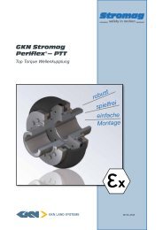
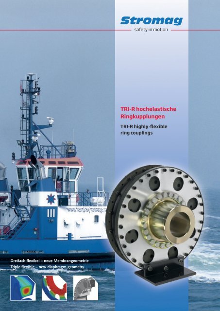
<strong>TRI</strong>-R <strong>hochelastische</strong><strong>Ringkupplungen</strong><strong>TRI</strong>-R highly-flexiblering couplingsDreifach flexibel – neue MembrangeometrieTriple flexible – new diaphragm geometry
<strong>TRI</strong>-R <strong>hochelastische</strong> <strong>Ringkupplungen</strong> – highly-flexible ring couplingsErwärmung und Temperaturverteilung durch Wechselbelastungder KupplungSimulation der Auslenkung einer Stahlmembrane für denAxialausgleichHeating and temperature distribution by alternatingstress of the couplingSimulation of excursion of a steel diaphragm for axialcompensationDie Kupplung TEF 523 W-RR verbindet die Feuerlöschpumpemit dem PTO- Antrieb des Dieselmotors.675 kW bei 1000 r.p.m. (Schiff = Schlepper GINGER,Motor = ABC- Diesel, Type 12 DZC)Kupplung TEF 641W-RR im Hauptantrieb eines Cargo- Binnenschiffes.1104 kW bei 800 r.p.m. (Motor ABC- Diesel)The coupling TEF 523 W-RR connects the fire-fightingpump and the PTO-drive of the diesel engine.675 kW at 1000 rpm (Vessel = tugboat GINGER, Engine= ABC diesel, type 12 DZC)Coupling TEF 641W-RR in the main drive of a cargo riverbarge. 1104 kW at 800 rpm (Engine = ABC diesel)
Hochelastische Stromag − KupplungHighly − flexible Stromag coupling<strong>TRI</strong> − RKatalog Nr. D 867Catalogue No. D 867Alle Angaben über Stromag <strong>TRI</strong> − R − Kupplungen in Druckschrif−ten älteren Datums sind mit Erscheinen dieser Druckschrift nurnoch bedingt gültig.Maß − und Konstruktionsänderungen behalten wir uns vor.This catalogue for Stromag <strong>TRI</strong> − R couplings cancels and repla−ces all former editions.We reserve the right to modify the dimensions and construc−tions.Stromag − Produkte entsprechen dem Qualitätsstandardnach DIN ISO 9001.Stromag products comply with the Quality Standard to DINISO 9001.InhaltSeiteContentPageDas <strong>TRI</strong> − R Konzept 2Einsatzgebiete, Hinweise für den Konstrukteur,Ex − Schutz − Einsatz, Klassifikationsvorschriften 3Durchdrehsicherung,Hinweise zur Auswahl der Kupplungsgröße 4Montagehinweise und LieferumfangLagerung von gummielastischen Elementen 5Kennwerte der Stromag − <strong>TRI</strong> − Kupplung 6 − 10Leistungstabelle 11Baureihe TEF....W − R 12 − 15Baureihe TEW....W − R 16 − 17Baureihe TEF....W − RR 18 − 21Baureihe TEW....W − RR 22 − 23Umrechnungsfaktoren 24Fragebogen 25Fragebogen ATEX 26Sonderbauformen 27 − 28<strong>TRI</strong> − R design 2Type of application, Hints for the designer,Explosion − .proof application, Classification regulations 3Emergency operation device,Hints for selection of the coupling 4Mounting hints and delivery extent,Storing of rubber flexible elements 5Characteristics of the Stromag − <strong>TRI</strong> − coupling 6 − 10Output table 11Series TEF....W − R 12 − 15Series TEW....W − R 16 − 17Series TEF....W − RR 18 − 21Series TEW....W − RR 22 − 23Conversion factors 24Questionnaire 25Questionnaire ATEX 26Special designs 27 − 281Datum / Date 08.2009
Hochelastische Stromag − KupplungHighly − flexible Stromag coupling<strong>TRI</strong> − RDas <strong>TRI</strong> − R KonzeptDie Stromag − <strong>TRI</strong> − R Kupplungen sind <strong>hochelastische</strong> Gummi−kupplungen mit linearer Federkennlinie, besonders geeignet fürdieselmotorische und elastisch aufgestellte Antriebe.Die Baureihe erstreckt sich über den Drehmomentbereich von1150 Nm bis 63000 Nm. Die äusseren Anschlussmasse entspre−chen bei Kupplungen bis 16000 Nm standardmäßig denSchwungradanschlüssen der SAE − Norm J620. Die grösserenKupplungen werden im Wesentlichen mit metrischenSchwungradanschlüssen ausgeführt.Die Stromag − <strong>TRI</strong> − R Kupplung ist die Kombination eines Ring −elementes aus gummielastischem Material mit einer Membranaus Federstahl. Das Ringelement ist drehnachgiebig und ge−währleistet zusätzlich eine radiale Nachgiebigkeit. Die Membrangewährleistet eine axiale Nachgiebigkeit, so daß die Kupplungin alle Richtungen verlagert werden kann.Für jede <strong>TRI</strong> − R Baugröße stehen unterschiedliche Elastomer −Qualitäten und Drehfedersteifen zur Verfügung. Dadurch ist eineexakte Abstimmung auf drehschwingungsgefährdete Antriebemöglich. Die Stromag − <strong>TRI</strong> − R Kupplung ist auch in mehr−reihigen Kombinationen von Ringelementen lieferbar.The <strong>TRI</strong> − R designThe Stromag couplings <strong>TRI</strong> − R are highly − flexible rubbercouplings with linear characteristic, which are in particular suita−ble for diesel engine and resiliently mounted drives.The torque range of this series is 1150 to 63000 Nm. With cou−plings up to 16000 Nm, as a standard the outer connectiondimensions comply with the flywheel connections of the SAEstandard J620. The larger couplings are mainly designed withmetric flywheel connections.The Stromag coupling <strong>TRI</strong> − R combines a ring element ofrubber − flexible material and a diaphragm of spring steel. Thering element is torsionally flexible and assures a radial flexibility.The diaphragm assures the axial flexibility, allowing offset of thecoupling in all directions.For each size <strong>TRI</strong> − R, various elastomer qualities and torsionalstiffnesses are available thus allowing the exact adaptation todrives subject to torsional vibrations. The Stromag coupling<strong>TRI</strong> − R can also be supplied in multi − row combinations of ringelements.DD − 8860291DD − 8860290Datum / Date 08.20092
Hochelastische Stromag − KupplungHighly − flexible Stromag coupling<strong>TRI</strong> − REinsatzgebieteDie Stromag − <strong>TRI</strong> − R Kupplung ist konzipiert für den Einsatz anKolbenmaschinen. Das Ringelement kann direkt an dasSchwungrad eines Motors angeschraubt werden. Bei ent−sprechender Ausführung lassen sich auch zwei Wellen oder zweiFlansche miteinander verbinden.Die Kupplung eignet sich aufgrund ihrer hohen axialen undradialen Verlagerungsfähigkeit hervorragend für den Einsatz anelastisch aufgestellten Antrieben. Durch das große Gummi−volumen wird außerdem eine gute Körperschall− Isolierungerreicht.Type of applicationThe Stromag <strong>TRI</strong> − R coupling has been designed for applicationwith piston engines. The ring element can be connected directlyto the flywheel of an engine. The connection of two shafts or twoflanges is also possible when executed accordingly.Due to its high axial and radial offset capacity, the coupling isideal for applications with resiliently mounted drives. A goodstructure− borne noise insulation is achieved by the great rubbervolume.Hinweise für den KonstrukteurDie Metallteile der <strong>TRI</strong> − R Kupplung sind aus Stahl. Das Ring −element wird aus unterschiedlichen Elastomer − Werkstoffen inverschiedenen Drehfedersteifen hergestellt.Die Ausführung aus Naturkautschuk (NR) ist im Temperaturbe−reich von − 50°C bis +80°C einsetzbar.Das elastische Element kann infolge Dämpfungsarbeit gegen−über der Umgebungstemperatur höhere Temperaturen errei−chen. Bei Verkleidung der Kupplung mit einer Schutz − oder Ab−deckhaube muß dieses berücksichtigt oder für ausreichendeBelüftung und Wärmeabfuhr gesorgt werden.Die Stromag − <strong>TRI</strong> − R Kupplung entspricht den Anforderungender Richtlinie 94/9/EG (ATEX 95) und kann in explosionsgefähr−deten Bereichen eingesetzt werden . Die Kupplung ist mitAbnahme nach EN 10204 gemäß den Vorschriften der Klassi−fikationsgesellschaftenlieferbar.Hints for the designerThe metal parts of the coupling <strong>TRI</strong> − R are made of steel. Thering element is made of different elastomer materials in varioustorsional stiffnesses.The design with natural rubber (NR) can be used within the tem−perature range from − 50°C up to +80°C.Due to the damping work, the flexible element can reach highertemperatures than the ambient temperature. When casing thecoupling by a protective or covering cap, this has to be takeninto consideration or a sufficient aeration and heat dissipationhas to be assured.The Stromag coupling <strong>TRI</strong> − R meets the requirements of direc−tive 94/9/EG (ATEX 95) and can be used in potentially explosivezones . The coupling can be supplied with approval to EN10204 as per the regulations of the classification societies.EX − Schutz − EinsatzDie Kupplung entspricht den Anforderungen der Richtlinie94/9/EG (ATEX 95) und kann folgendermaßen eingesetzt wer−den:a. In der Zone 1 (Gas − Ex, Kategorie 2G) in den Explosionsgrup−pen IIA, IIB und IIC, T4,b. In der Zone 2 (Gas − Ex, Kategorie 3G) in den Explosionsgrup−pen IIA, IIB und IIC, T4,c.. In der Zone 22 (Staub − Ex, Kategorie 3D) bei Stäuben mit einerMindestzündenergie > 3mJ, T125°C,Bei Ex − Schutz − Einsatz ist das Anfrageformular am Ende desKataloges zu berücksichtigen.Explosion − proof applicationThe coupling meets the requirements of directive 94/9/EG (ATEX95) and can be used as follows:a. In Zone 1 (Gaz − Ex, category 2G) in explosion groups IIA, IIBand IIC, T4,b. In Zone 2 (Gaz − Ex, category 3G) in explosion groups IIA, IIBand IIC, T4,c.. In Zone 22 (Dust − Ex, category 3D) with dusts having a min. fi−ring power > 3mJ, T125°C,With explosion − proof application, adhere to the inquiry form atthe end of the catalogue.KlassifikationsvorschriftenBei Abnahme der Kupplung durch eine Klassifikationsgesell−schaft sind deren Vorschriften zu berücksichtigen. Dabei könnensich die Kupplungskennwerte von den in diesem Katalog darge−stellten Definitionen unterscheiden. Entsprechend aufbereiteteDatenblätter stehen auf Anfrage zur Verfügung.Von einigen Klassifikationsgesellschaften werden für Schiffs−hauptantriebe Durchdrehsicherungen vorgeschrieben.Classification regulationsFor survey of the coupling by a classification society, the regula−tions of the society have to be adhered to. The coupling charac−teristics may differ from the definitions given in this catalogue.Accordingly prepared data sheets are available on request.Some classification societies require emergency operation devi−ces for marine main drives.3Datum / Date 08.2009
Hochelastische Stromag − KupplungHighly − flexible Stromag coupling<strong>TRI</strong> − RDurchdrehsicherungDie Stromag − <strong>TRI</strong> − R Kupplung ist mit einer Durchdrehsiche−rung lieferbar. Bei Bruch der elastischen Elemente ist eine dreh−starre und spielbehaftete Verbindung der An − und Abtriebsseitedurch ineinandergreifende Klauen realisiert. Ein zeitlich einge−schränkter Notbetrieb mit begrenztem Drehmoment ist möglich.Die dabei zulässigen Drehmomente und Drehzahlen sind durcheine Drehschwingungsberechnung mit drehstarrer Übertragunggesondert zu berechnen.Emergency operation deviceThe Stromag coupling <strong>TRI</strong> − R can be supplied with an emer−gency operation device (i.e. safety device against spinning).With rupture of the flexible elements, a torsionally stiff connectionwith free play between the input and output sides is achievedby meshing claws. A time − limited emergency operation withlimited torque is possible. The admissible torque and speed rat−ings have to be calculated separately by a torsional vibrationcaculation with torsionally stiff transmission.DD 8860292Hinweise zur Auswahl der KupplungsgrößeFür Stromag − <strong>TRI</strong> − R Kupplungen liegen die statischen unddynamischen Kennwerte vor. Mit ihrer Hilfe ist es möglich, diegeeignete Kupplungsgröße für den vorliegenden Antriebsfallauszuwählen. Maßgebend dafür sind die Belastungen ausüber − tragener Leistung und Drehschwingungsbelastungen.Für stationäre Betriebszustände sind T KN , T KW und P KV , für insta−tionäre Betriebszustände sind die T Kmax − Werte heranzuziehen.Unterstützung bei der Auslegung, insbesondere der Dreh−schwingungsberechnung, ist durch die Fachabteilungen derStromag AG möglich. Dazu bitten wir, den Fragebogen am Endedes Kataloges zu kopieren und uns ausgefüllt zuzusenden.Elastische Kupplungen stellen in der Regel die sicherheits−technische Sollbruchstelle eines Antriebsstranges dar.Überlastungen des Antriebsstranges führen deshalb in allerRegel zu einem Versagen der elastischen Kupplungselemente.Dieses Verhalten ist gewollt und schützt die Gesamtanlage vorunvorhergesehenen Beschädigungen. Folgeschäden, die ausdieser Sicherheitsfunktion der Kupplung resultieren, sind vomAnlagenkonstrukteur im voraus zu berücksichtigen und durchgeeignete Maßnahmen zu überwachen bzw. zu verhindern.Hints for selection of the coupling sizeFor Stromag couplings <strong>TRI</strong> − R the static and dynamic characteri−stics are known. On the basis of these characteristics it is possi−ble to select the suitable coupling size for the actual application.The decesive factors are the transmitted power and the torsionalvibration charges. For stationary system conditions use T KN , T KWand P KV ; for nonstationary system conditions use T Kmax .The technical departments of Stromag AG are pleased to assistwith the selection of the coupling, in particular by a torsionalvibration calculation. To that effect, please copy the question−naire given in this catalogue, complete and return it to us.Normally the flexible couplings present the predetermined brea−king point of a drive line.Overloading of the drive line normally results in the failure of theflexible coupling elements. This behaviour is intended and pro−tects the entire system against unexpected damage. Conse−quential damage resulting from this safety function of the cou−pling has to be taken into consideration in advance by thesystem designer and has to be monitored or prevented resp. bysuitable measures.Datum / Date 08.20094
Hochelastische Stromag − KupplungHighly − flexible Stromag coupling<strong>TRI</strong> − RMontagehinweise und LieferumfangDie Stromag − <strong>TRI</strong> − R Kupplung kann mit ihrem Ringelement (3)über den Anschlußflansch (4) direkt an das Schwungrad einesMotors angeschraubt werden. Die Gegenseite des Ringelemen−tes (3) wird über den Zentrierring (6) mit der Membran (8) ver−schraubt, welche das Drehmoment über die Verbindung mitDruckring (7) über die Nabe (1) auf eine angeschlosseneMaschine,ein Getriebe o.ä. überträgt.Das Ringelement der Baugröße 12 ist in 2 Hälften geteilt, so daßeine einfache radiale Montage gewährleistet ist.Zum Lieferumfang einer Stromag <strong>TRI</strong> − R Kupplung in Standardausführung gehören:The delivery extent of the Stromag <strong>TRI</strong> − R coupling in standard execution comprises:Mounting hints and delivery extentThe Stromag coupling <strong>TRI</strong> − R can be screwed directly to theflywheel of the engine by means of its ring element (3) throughthe connection flange (4). Through the center ring (6), the coun−terside of the ring element (3) is screwed to the diaphragm (8)which transmits the torque to a connected machine, a gearbox,or similar through the connection with the pressure ring (7) viathe hub (1).The ring element of size 12 is split into 2 halves in order to as−sure a simple radial mounting.1 = Nabe / Hub3 = Ringelement / Ring element4 =Anschlußflansch / Connection flange6 = Zentrierring / Center ring7 = Druckring / Pressure ring8 = Membran / Diaphragm9, 10, 11, 15 = Schrauben / Screws12 = Mutter / Nut14 = Scheibe / WasherDD 886058Lagerung von gummielastischen ElementenBei einer geeigneten Lagerung behalten gummielastischeElemente ihre Eigenschaft über mehrere Jahre unverändert bei.Wesentlich ist, die gelagerten Teile vor Sauerstoff, Ozon, Licht,Wärme, Feuchtigkeit und Lösungsmitteln zu schützen.Lösungsmittel, Kraftstoffe, Schmierstoffe, Chemikalien, Säuren,Desinfektionsmittel und ähnliches dürfen im Lagerraum nichtaufbewahrt werden. Die Lagertemperatur sollte +10C nichtunter − und +25C nicht überschreiten. Alle Lichtquellen mit ul−traviolettem Licht sind schädlich und zu vermeiden. Ozonerzeu−gende Einrichtungen, wie z.B. Lichtquellen und Elektromotoren,sind vom Lagerort fernzuhalten. Die relative Luftfeuchtigkeitsollte 65% nicht überschreiten.Weitere Einzelheiten können dem Blatt DIN 7716 entnommenwerden.Gummielastische Elemente aus temperaturbeständigem MaterialECO sind ozon − und ölbeständig im Vergleich zum Natur−gummi.DD 886129Storing of rubber flexible elementsWhen suitably stored, rubber flexible elements maintain theircharacteristics for several years without change.It is of great importance to protect the stored parts against oxy−gen, ozone, heat, light, moisture and solvents.Solvents, fuels, lubricants, chemicals, acids, disinfectants etc.must not be stored in the same room with the elements. Thetemperature in the store should be between +10C and +25C.All light sources emitting ultra − violet rays are dangerous andshould be avoided. Ozone producing equipment such as lightsand electric motors should be kept away from the storage area.The relative humidity should not exceed 65%.Further details are given on DIN sheet 7716.Compared with elements made of natural rubber, rubber − flex−ible elements made of temperature − resistant material ECO areozone and oil resistant.5Datum / Date 08.2009
Kennwerte der Stromag − <strong>TRI</strong> − R KupplungCharacteristics of the Stromag coupling <strong>TRI</strong> − RT KNDas Nenndrehmoment der Kupplung kann im gesamten zulässi−gen Drehzahlbereich dauernd übertragen werden. Es darf vomNenndrehmoment T N der Anlage nicht überschritten werden.T KNThe nominal torque of the coupling can be transmitted continu−ously over the admissible speed − range. The nominal torque T Nof the installation must not exceed that of the coupling.T KN > T NT KN > T NT Kmax1Das Maximaldrehmoment T Kmax1 der Kupplung kann als Spit−zenbelastung ertragen werden und darf von normalen instatio−nären Spitzendrehmomenten T max1 der Anlage nicht überschrit−ten werden.T Kmax1The max torque T Kmax1 of the coupling can be accepted as peakload; it must not be exceeded by normal non − stationary peaktorques T max1 of the system.T Kmax1 > T max1Normale instationäre Betriebszustände einer Anlage sind unver−meidbar und treten wiederkehrend auf (z.B.: Start − und Stop−vorgänge, Resonanzdurchfahrt, Umschaltvorgänge, Beschleuni−gungsvorgänge, etc.).T Kmax1 > T max1Normal non − stationary operation conditions of a system cannotbe avoided and re − occur (e.g. start and stop processes, reso−nance run, change − over processes, accelerations, etc.).T Kmax2Das Maximaldrehmoment T Kmax2 der Kupplung kann als seltenauftretende Spitzenbelastung ertragen werden und darf von ab−normalen instationären Spitzendrehmomenten T max2 der Anlagenicht überschritten werden.T Kmax2The max. torque T Kmax2 of the coupling can be accepted asrarely occurring peak load and must not be exceeded by normalnon − stationary peak torques T max2 of the system.T Kmax2 > T max2Abnormale instationäre Spitzendrehmomente einer Anlage sindvermeidbar und gehören nicht zum geplanten Betriebsbild(z.B.: Not − Aus, Fehlsynchronisation, Kurzschluß, etc.).Eine Überlastung der Stromag − <strong>TRI</strong> − R Kupplung durch abnor−male instationäre Spitzendrehmomente T max2 der Anlage istlebensdauerverkürzend und wird in Einzelfällen toleriert.T Kmax2 > T max2Abnormal non − stationary peak torques of a system can be avoi−ded and do not belong to the intended operation (e.g.: emer−gency stop, missynchronisation, short − circuit, etc.).An overloading of the Stromag coupling <strong>TRI</strong> − R by abnormalnon − stationary peak torques T max2 of the system reduces thelifetime and in single cases it is tolerated.T KWDas zulässige Dauerwechseldrehmoment gibt die Amplitude derdauernd zulässigen, periodischen Drehmomentschwankung an.Dieses Drehmoment darf einer Grundlast in der Größe von T KNüberlagert werden.Dabei muß zusätzlich die zulässige Dämpfungsleistung P KVüberprüft werden.T KWThe permissible continuous alternating torque states the amplitu−de of the permissible continuous periodic torque variations. Thistorque may be superimposed upon the basic load equal to T KN .With torsional vibration stress, the admissible damping outputP KV must also be checked. K aZulässige axiale Verlagerung der Kupplung. Die axiale Verlage−rung W a der Wellen muß kleiner als K a sein. K aPermissible axial offset of the coupling.The axial offset W a of the shafts must be smaller K a .K a > W aK a > W aDatum / Date 08.20096
Kennwerte der Stromag − <strong>TRI</strong> − R KupplungCharacteristics of the Stromag coupling <strong>TRI</strong> − R K rZulässige radiale Verlagerung der Kupplung. Die radiale Verlage−rung W r der Wellen muß kleiner als K r sein. K rPermissible radial offset of the coupling. The radial offset W rof the shafts must be smaller K r .K r > W rDie bei der Stromag <strong>TRI</strong> − R Kupplung angegebenen Werte fürK r beziehen sich auf Drehzahlen der Kupplungswelle bis zu600 min −1 . Die Umrechnung auf eine andere Drehzahl erfolgtnach der BeziehungK r > W rThe value of K r stated for the Stromag coupling <strong>TRI</strong> − R reffersto coupling shaft speeds up to 600 rpm. The conversion to otherspeeds is made by the equationK r (n)=600 min −1n K rK r (n)=600 min −1n K rDie zulässige radiale Verlagerung muß bei Umgebungstempera−turen über 30C um den Temperaturfaktor S ϑKr reduziert wer−den.With ambient temperatures higher than 30C, the admissible ra−dial offset must be reduced by the temperature factor S ϑKr .K r (T U )=K rSϑKrK r (T U )=K rSϑKr K WZulässige winkelige Verlagerung der Kupplung.Die winkelige Verlagerung der Wellen W W muß kleiner als K Wsein. K WPermissible angular offset of the coupling.The angular offset of the shafts W W must be smaller K W .K W > W WFür Stromag − <strong>TRI</strong> − R Kupplungen ist ein K W von 0,5 zulässig.Dieser Wert darf jedoch nur ausgenutzt werden, wenn keineweiteren Wellenverlagerungen vorliegen.K W > W WFor Stromag couplings <strong>TRI</strong> − R a K W of 0.5 is admissible.However, this value must only be used when no other axial shaftoffset exists.F aDie axiale Rückstellkraft der Membran wird für eine Verlagerungvon 1mm angegeben. Stahlmembranen haben eine progressiveKennlinie. Formeln für die Berechnung von größeren axialen Ver−lagerungen auf Anfrage.F aThe axial restoring force of the diaphragm is stated for an offsetof 1 mm. Steel diaphragms have a progressive characteristic.Forms for the calculation of larger axial offsets on request.C rDie Radialfedersteife gibt die Beziehung zwischen radialer Rück−stellkraft und dem Radialversatz an. Die angegebenen Wertesind gültig für die betriebswarme Kupplung, mit einer Ober−flächentemperatur von ca. 30°C.C rThe radial stiffness mentions the relation between radial resto−ring force and radial offset. The stated values apply to the cou−pling at working temperature, with a surface temperature of ap−prox. 30°C.7Datum / Date 08.2009
Kennwerte der Stromag − <strong>TRI</strong> − R KupplungCharacteristics of the Stromag coupling <strong>TRI</strong> − RC TdynDie dynamische Drehfedersteife gibt die Beziehung einer Dreh−momentamplitude zur Drehwinkelamplitude während einesSchwingungsvorganges an.C TdynThe dynamic stiffness mentions the relation of a torque ampli−tude to the rotary angle amplitude during a vibration process.C Tdyn =T elWC Tdyn =T elWDie Drehmomentamplitude ist einer Vorlast (Kupplungsdrehmo−ment) überlagert. Bei der Stromag − <strong>TRI</strong> − R Kupplung ist derC Tdyn − Wert über dem Kupplungsdrehmoment konstant (lineareKennlinie), verändert sich aber mit der Größe der Amplitude, derFrequenz und der Temperatur des elastischen Elementes.Die Angaben für C Tdyn beziehen sich auf ein Kupplungsdrehmo−ment von 0,8 x T KN , ein Wechseldrehmoment von 0,2 x T KN, eineFrequenz von 10 Hz, bei betriebswarmer Kupplung mit einerOberflächentemperatur von ca. 50°C.Die verhältnismäßige Dämpfung ist ein Maß für die Fähigkeit derKupplung, einen Teil der anfallenden Schwingungsenergie inWärme umzuwandeln.Die Dämpfung kann mit der Dämpfungsschleife (Hysterese−schleife) ermittelt werden.The torque amplitude is superimposed to a pre − load (couplingtorque). For the Stromag coupling <strong>TRI</strong> − R the value C Tdyn is con−stant over the coupling torque (linear characteristic line). It chan−ges, however, in relation to the amplitude, the frequency and thetemperature of the flexible element.The data for C Tdyn relates to a coupling torque of 0,8 x T KN , analternating torque of 0,2 x T KN, a frequency of 10 Hz, with acoupling at working temperature with a surface temperature ofapprox. 50°C.The proportional damping is a factor for the capacity of a cou−pling to convert a part of the occurring cyclic energy into heat.The damping can be determined by the damping loop (hystere−sis loop).W D= =W elA DA elW D= =W elA DA elDie Fläche A D ist ein Maß für die Dämpfungsarbeit W D währendeines Schwingungszyklus.Die Fläche A el stellt die elastische Formänderungsarbeit W el beieiner Belastung dar.Die Angaben für beziehen sich auf ein Kupplungsdrehmomentvon 0,8 x T KN , ein Wechseldrehmoment von 0,2 x T KN , eineFrequenz von 10 Hz, bei betriebswarmer Kupplung mit einerOberflächentemperatur von ca. 50°C.The area A D is a factor for the damping work W D during a vibrati−on cycle.The area A el represents the work done in deflection W el at a gi−ven load.The data for relates to a coupling torque of 0,8 x T KN , an alter−nating torque of 0,2 x T KN , a frequency of 10 Hz, with a couplingat working temperature with a surface temperature of approx.50°C.C Tdyn =T elW=A DA elTTTwT el WAA Del ϕwDD870010300ϕϕDatum / Date 08.20098
Kennwerte der Stromag − <strong>TRI</strong> − R KupplungCharacteristics of the Stromag coupling <strong>TRI</strong> − RP KVDie zulässige Dämpfungsleistung gibt an, wieviel Dämpfung(Wärme) die Kupplung dauerhaft aufnehmen bzw. abführenkann. Die Summe der Dämpfungsleistung aus jederSchwingungsordnung (d.h. P Vi ) muß kleiner sein als dieDämpfungsleistung der Kupplung.P KVThe admissible damping capacity indicates how much damping(heat) the coupling can permanently absorb resp. dissipate. Thesum of the damping power of each vibration order (i.e. P Vi )must be less than the damping power capacity of the coupling.P Vi = π2 πψ2+1T Wi2 f iC TdynP KV P ViDer angegebene P KV60 − Wert beschreibt die über eine Dauervon einer Stunde aufnehmbare Dämpfungsleistung. Zur Ermitt−lung der dauerhaft aufnehmbaren Dämpfungsleistung (P KV ) istder P KV60 − Wert mit dem Faktor 0,5 zu multiplizieren.Die zulässige Dämpfungsleistung muß bei Umgebungstempera−turen über 30C um den Temperaturfaktor S PKV reduziert wer−den.PP KV (T U ) = KVSPKVThe stated value P KV60 describes the damping capacity whichcan be absorbed over the period of 1 hour. To determine thedamping capacity which can be permanently absorbed (P KV ),the value P KV60 has to be multiplied by the factor 0.5.With an ambient temperature higher than 30C, the admissibledamping capacity must be reduced by the temperature factorS PKV .PP KV (T U ) = KVSPKV9Datum / Date 08.2009
Kennwerte der Stromag − <strong>TRI</strong> − R KupplungCharacteristics of the Stromag coupling <strong>TRI</strong> − RTemperaturfaktoren S Kr und S PKVTemperaturfaktoren sollen das Absinken der physikalischenEigenschaften von gummielastischen Werkstoffen durch zuhohe Erwärmung berücksichtigen.Die Kupplungstemperatur ist bestimmt durch die Umgebungs −temperatur zuzüglich einer inneren Erwärmung, hervorgerufendurch Dämpfung im Gummivolumen, in Folge von Wechsel−drehmomenten und Wechselbelastungen durch Wellenversatz.Bei höheren Umgebungstemperaturen müssen die Kupplungs −kennwerte K r und P KV über die jeweiligen TemperaturfaktorenS Kr und S PKV reduziert werden.Temperature factors S Kr and S PKVTemperature factors shall take into consideration the reductionof the physical characteristics of rubber − flexible material causedby heating.The coupling temperature is determined by the ambient temper−ature plus an internal heating caused by internal material frictionin the rubber volume, resulting from alternating torques and al−ternating loads due to shaft offsets.With higher ambient temperatures the coupling characteristicvalues K r and P KV must be reduced through the correspon−ding temperature factors S Kr and S PKV .Korrekturfaktoren: SCorrection factors:Umgebungstemperatur / Ambient temperature (C)DD886009Datum / Date 08.200910
Leistungstabelle / Output tableBaureihe / Series TE..... − R<strong>TRI</strong>Kupplungsgröße<strong>TRI</strong> − Cou−plingSizeNenndrehmomentNominalTorqueMaximaldrehmomentMaximumTorqueZul. Wechsel−drehmomentAdm.Alterna−ting TorqueZul.DrehzahlAdm.SpeedZul. axialeVerlagerungAdm.AxialDisplace−mentAxialeRückstellkraftAxialReactionForceZul. radialeVerlagerungAdm.RadialDisplace−mentZul.max.radialeVerlagerungAdm.max.RadialDisplacementRadialfedersteifeRadialStiffnessDrehfeder−steifeTorsionalStiffnessVerhältnis−mäßigeDämpfungRelativeDampingZul.Dämpfungs−leistungAdm.DampingPower311 R312 R313 R321 R322 R323 R411 R412 R413 R421 R422 R423 R431 R432 R433 R511 R512 R513 R521 R522 R523 R641 R642 R643 R741 R742 R743 R841 R842 R843 R941 R942 R943 R1041 R1042 R1043 R1141 R1142 R1143 R1241 R1242 R1243 RT KNNm115013501950165019502350255040003600520043506650690011400855014800160001600016000200002000020000250002500025000315003150031500400004000040000500005000050000630006300063000T Kmax1Nm1)170020002900250029003500380060005400780065001000010400171001280022200240002400024000300003000030000375003750037500472504725047250600006000060000750007500075000947509475094750T Kmax2Nm2)3400400058005000580070007600120001080015600130002000020800342002560044400480004800048000600006000060000750007500075000945009450094500120000120000120000150000150000150000189000189000189000T KWNm28533548541548558563510009001300109016701730285021403700400040004000500050005000625062506250787578757875100001000010000125001250012500158001580015800n maxmin −13800380038003800380038002800280028002800280028002300230023002300210021002100200020002000190019001900175017501750160016001600150015001500100010001000K amm3)3333334444445555666666666666666666777F akN8)0,260,260,260,260,260,260,270,270,270,270,270,270,450,450,450,450,600,600,600,900,900,900,920,920,920,920,920,921,11,11,11,11,11,11,61,61,6K rmm4) 6)3323324343435454666666666666777777999K r maxmm6)664664868686108108121212121212121212121212141414141414181818C rkN/mm7)0,380,520,750,490,751,00,721,11,01,21,11,71,42,01,92,41,42,03,61,62,44,21,62,74,51,93,15,12,03,35,62,23,66,02,54,06,8C T dynkNm/rad5) 7)6,99,513,59,414,520,022,534,531,540,039,057,570,096,0100127851202101051602751252103451702754602103505902754407403505509505) 7)0,81,01,10,81,01,11,01,11,01,11,01,11,01,11,01,10,71,01,10,71,01,10,71,01,10,71,01,10,71,01,10,71,01,10,71,01,1P KV 60W6) 9)2602602603403403403603604404405105105805806306306806806808008008009009009009609609601080108010801160116011601240124012401) für periodische kurzzeitige Schwingungen während Start/Stop, Schaltung usw.for transient repetitive vibrations durin start/stop, clutching etc.2) für selten auftretende Spitzenbelastungen, z.B. Generator − Kurzschlußfor rare occasional peak loads, e.g. short circuits in generators3) dyn. axiale Verlagerung K a dyn = 0.33 K adyn. axial displacement K a dyn = 0.33 K a5) bei / at: TW = 0.2 T KN ; T = 0.8 T KN ; f = 10 Hz; ϑ = 30°C6) Dieser Wert muß bei Kupplungstemperaturen, höher als 30°C,über den Temperaturfaktor reduziert werden /For coupling temperatures exceeding 30°C, this value mustbe reduced by the temperature factor7) Materialbedingte Toleranzen bis zu ±15% sind möglich /Tolerances until ±15% related to the material are possible4) bei/at n max = 600 min −1 ,für höhere Drehzahlen / for higher speed ratings:K r (n)=600 min −1n K r8) bei Wellenverlagerung /at shaft offset W a = 1 mm9) Der P KV 60 − Wert beschreibt die über eine Dauer von 60 Min.aufnehmbare Dämpfungsleistung. Dauerhaft aufnehmbareDämpfungsleistung P KV = 0.5 P KV 60 /The value P KV 60 describes the damping capacity to be absorbedover 1 hour. Permanently absorbed damping capacity P KV = 0.5 P KV 6011Datum / Date 08.2009
Baureihe / SeriesTEF....W − Rw1m1w1m1w2m2w2m2B − Seite / SideAbb./Fig. 1A − Seite / SideJ2 J1J2 J1C Tdyn(R)B − Seite / SideC Tdyn(R)A − Seite / SideAbb./Fig. 2DD 886034 DD 886031Kupplungsgröße / Coupling size 31 32 41 42Schwungradanschluß nach SAE J 620Flywheel Connection to SAE J 62011.5" 14" 11.5" 14" 14" 16" 14" 16" 18"Abbildung / Fig. 1 2 1 2 1 2 1 2 2Durchmesser mmDiameterLängen mmLengthsd 1 vor30d 1 max85a 1352.4b 1333.4e 1360e 2360h 1120h 2300k 18x11**l 1 191n 1105p 189o 118s 16w 115.5w 2* 873085466.7438.2360−1201758x13.51861058912−9873085352.4333.43603601203008x11**191105891861687.53085466.7438.2360−1201758x13.51861058912−987.535120466.7438.2475−1684058x13.5**1951058322−188435120517.5489475−1682458x13.51881058315−11.58435120466.7438.2475−1684058x13.5**1951058322−18.584.535120517.5489475−1682458x13.51881058315−1284.535120571.5542.9475−16824512x17.51881058315−11.584.5Massen kgMassesm 1m 2 *10.813.416.613.410.913.516.713.522.227.924.527.922.528.224.828.230.328.22Mass.trägh.mom. kgmMass mom. of inertiaJ 1J 2 *0.2160.1920.4740.1920.2200.1950.4780.1950.7700.6910.9390.6910.7800.7010.9500.7011.3540.701*) bei max. Bohrungsdurchmesser / at max. bore diameter; Weitere Kupplungsgrößen auf Anfrage / Other coupling sizes on request**) + Ansenkung für Zylinderschraube / + countersunk for cyl. screws ISO 4762Maß − bzw. Konstruktionsänderungen vorbehalten / Dimensions and construction subject to changeDatum / Date 08.200912
Baureihe / SeriesTEF....W − Rw1m1w1m1w2m2w2m2B − Seite / SideAbb./Fig. 1A − Seite / SideJ2 J1J2 J1C Tdyn(R)B − Seite / SideC Tdyn(R)A − Seite / SideAbb./Fig. 2DD 886034 DD 886031Kupplungsgröße / Coupling size 43 51 52Schwungradanschluß nach SAE J 620Flywheel Connection to SAE J 62014" 16" 18" 18" 21" 18" 21" 24"Abbildung / Fig. 1 2 2 1 2 1 2 2Durchmesser mmDiameterLängen mmLengthsd 1 vor35d 1 max120a 1466.7b 1438.2e 1475e 2−h 1168h 2405k 18x13.5**l 1 195n 1105p 183o 122s 1−w 119w 2* 8535120517.5489475−1682458x13.51881058315−12.58535120571.5542.9475−16824512x17.51881058315−11.58555150571.5542.960858021050512x17.5**289175146.52572214255150673.1641.4608−21029212x17.5279175146.515−1314255150571.5542.960858021050512x17.5**272175146.52572313455150673.1641.4608−21029212x17.5262175146.515−13.513455150733.4692.2608−21029212x20262175146.515−12.5134Massen kgMassesm 1m 2 *22.728.42528.430.528.438.267.944.467.93958.245.258.25358.22Mass.trägh.mom. kgmMass mom. of inertiaJ 1J 2 *0.7900.7110.9590.7111.3640.7112.0342.7512.7632.7512.0882.0252.8172.0253.7892.025*) bei max. Bohrungsdurchmesser / at max. bore diameter; Weitere Kupplungsgrößen auf Anfrage / Other coupling sizes on request**) + Ansenkung für Zylinderschraube / + countersunk for cyl. screws ISO 4762Maß − bzw. Konstruktionsänderungen vorbehalten / Dimensions and construction subject to change13Datum / Date 08.2009
Baureihe / SeriesTEF....W − RB − Seite / SideA − Seite / SideAbb./Fig. 1 Abb./Fig. 2DD 886085DD 886086Kupplungsgröße / Coupling size 64 74AnschlußConnectionmetr. 18" 21" 24" metr. 21" 24"Abbildung / Fig. 1 2 2 2 1 1 2Durchmesser mmDiameterLängen mmLengthsd 1 vor80d 1 max160a 1635b 1608e 1645e 2645h 1230h 2568k 132x13.5l 1 307n 1185p 1157o 126s 112w 127,5w 2* 15180160571,5542,964564523049012x17,531518515715***835,5145,580160673,1641,4645−23056812x17.53151851578,5**−35145,580160733,4692,2645−23056812x2030718515723−33145,58517068065069269224061032x15,5332200170281230165,585170673,1641,469269224060012x17,533220017028124015985170733,4692,2692−24061012x2034220017010,5**−38159Massen kgMassesm 1m 2 *28,386,746,281,845,981,839,281,834,9102,941,297,460,997,42Mass.trägh.mom. kgmMass mom. of inertiaJ 1J 2 *2,1233,3173,1923,1643,5673,1643,2763,1642,9824,6143,2284,4265,6324,426*) bei max. Bohrungsdurchmesser / at max. bore diameter; Weitere Kupplungsgrößen auf Anfrage / Other coupling sizes on request**) + Ansenkung für Zylinderschraube / + countersunk for cyl. screws ISO 4762Maß − bzw. Konstruktionsänderungen vorbehalten / Dimensions and construction subject to change***) + Ansenkung für Sechskantschraube ISO 4017 /Datum / Date 08.200914
Baureihe / SeriesTEF....W − RAbb./Fig. 1B − Seite / SideA − Seite / SideAbb./Fig. 2DD 886085DD 886086Kupplungsgröße / Coupling size 84 94 104 114 124AnschlußConnectionmetr. 24" metr. metr. metr. metr.Abbildung / Fig. 1 1 1 1 1 1Durchmesser mmDiameterLängen mmLengthsd 1 vor90d 1 max185a 1730b 1700e 1740e 2740h 1260h 2655k 132x15,5l 1 367n 1225p 1192o 130s 114w 143,5w 2* 17790185733,4692,274074026065512x2036722519230144317710020079075580480428070632x17,5385235198321546,518511022086082087587530876532x20413250210331749,519812023592088093593533082032x20451275231371858,02191252559959501010−35890532x21355315167121233183Massen kgMassesm 1m 2 *48,4121,848,8121,859,9153,074,0203,4104,3252,984,0316,02Mass.trägh.mom. kgmMass mom. of inertiaJ 1J 2 *4,4106,1314,4686,1316,4589,2139,44414,5615,3221,2411,9428,62*) bei max. Bohrungsdurchmesser / at max. bore diameter; Weitere Kupplungsgrößen auf Anfrage / Other coupling sizes on request**) + Ansenkung für Zylinderschraube / + countersunk for cyl. screws ISO 4762Maß − bzw. Konstruktionsänderungen vorbehalten / Dimensions and construction subject to change15Datum / Date 08.2009
Baureihe / SeriesTEW...W − Rw2m2m1w1B − Seite / SideJ2C Tdyn(R)J1A − Seite / SideDD 886029Kupplungsgröße / Coupling size 31 32 41 42 43 51 52d 1 vor30303535355555h 2 120120168168168210210d 1 max8585120120120150150d 2 vor30303535355555d 2 max8585120120120150150e 1360360475475475608608e 2314317417420420520525h 1120120168168168210210l 1 272272277277277432432n 1105105105105105175175w 2* 8787.58787.588142 141.5n 2105105105105105175175p 18989838383 146.5 146.5p 2101101100100100169169w 1 *8080.5 79.5 80.581 129.5 130.5Durchmesser mmDiameterLängen mmLengthsMassen kgMassesm 1 *m 2 *10.913.41113.521.929.422.229.722.429.948.067.948.864.82Mass.trägh.mom. kgmMass mom. of inertiaJ 1 *J 2 *0.0820.1920.0860.1950.3060.7630.3170.7740.3260.7830.9682.7511.0222.553*) bei max. Bohrungsdurchmesser / at max. bore diameter; Weitere Kupplungsgrößen auf Anfrage / Other coupling sizes on requestMaß − bzw. Konstruktionsänderungen vorbehalten / Dimensions and construction subject to changeDatum / Date 08.200916
Baureihe / SeriesTEW...W − RB.Seite / SideA − Seite / SideDD 886083Kupplungsgröße / Coupling size 64 74 84 94 104 114 124d 1 vor808590100110120125h 2 230240260280308330358d 1 max160170185200220235255d 2 vor808590100110120125d 2 max160170185200220235255e 1645692740804875935 1010e 2645692740804875935 1010h 1230240260280308330358l 1 496537596624668734684n 1185200225235250275315w 2* 145,5 159177 185,0 198,0 219183n 2185200225235250275290p 1157170192198210231167p 2185200225235250277293w 1 *172,5 189,5 209,5 218,5 235,5 261272Durchmesser mmDiameterLängen mmLengthsMassen kgMassesm 1 *m 2 *116,381,8143,297,4177121,8218,5153,0266,5203,4361,4252,9444,0316,02Mass.trägh.mom. kgmMass mom. of inertiaJ 1 *J 2 *4,8993,1647,0364,4269,7716,13114,309,21321,0514,5632,6421,2446,2728,62*) bei max. Bohrungsdurchmesser / at max. bore diameter; Weitere Kupplungsgrößen auf Anfrage / Other coupling sizes on requestMaß − bzw. Konstruktionsänderungen vorbehalten / Dimensions and construction subject to change17Datum / Date 08.2009
Baureihe / SeriesTEF....W − RRw2m2m1w1w2m2m1w1w3m3w3m3B − Seite / SideAbb./Fig. 1A − Seite / SideJ3 J2 J1J3 J2 J1B − Seite / SideC Tdyn(R)C Tdyn(R)C Tdyn(R) C Tdyn(R)A − Seite / SideAbb./Fig. 2DD 886032 DD 886035Kupplungsgröße / Coupling size 31 32 41 42Schwungradanschluß nach SAE J 620Flywheel Connection to SAE J 62011.5" 14" 11.5" 14" 14" 16" 14" 16" 18"Abbildung / Fig. 1 2 1 2 1 2 1 2 2Durchmesser mmDiameterLängen mmLengthsd 1 vor30d 1 max85a 1352.4b 1333.4e 1360e 2360h 1120h 2300k 18x11l 1 231n 1105p 189o 116s 18w 113.5w 2160w 3* 88.53085466.7438.2360−1203008x13.52311058916−1016088.53085352.4333.43603601203008x112311058916819.5160.5893085466.7438.2360−1203008x13.52311058916−10.5160.58935120466.7438.24754751684058x13.52251056519915.514774.535120517.5489475−1684058x13.52251056518−1314774.535120466.7438.24754751684058x13.52251056519916.51477535120517.5489475−1684058x13.52251056518−13.51477535120571.5542.9475−16840512x17.52251056518−12.514775Massen kgMassesm 1m 2m 3 *5.17.614147.6145.27.914.114.27.914.19.714.929.314.814.929.31015.529.615.115.529.621.615.529.62Mass.trägh.mom. kgmMass mom. of inertiaJ 1J 2J 3 *0.1260.1060.1670.5120.1060.1670.1290.1140.1710.5160.1140.1710.4240.3740.6610.7340.3740.6610.4350.3950.6720.7450.3950.6721.2300.3950.672*) bei max. Bohrungsdurchmesser / at max. bore diameter; Weitere Kupplungsgrößen auf Anfrage / Other coupling sizes on requestMaß − bzw. Konstruktionsänderungen vorbehalten / Dimensions and construction subject to changeDatum / Date 08.200918
Baureihe / SeriesTEF....W − RRw2m2m1w1w2m2m1w1w3m3w3m3B − Seite / SideAbb./Fig. 1A − Seite / SideJ3 J2 J1J3 J2 J1B − Seite / SideC Tdyn(R)C Tdyn(R)C Tdyn(R) C Tdyn(R)A − Seite / SideAbb./Fig. 2DD 886032 DD 886035Kupplungsgröße / Coupling size 43 51 52Schwungradanschluß nach SAE J 620Flywheel Connection to SAE J 62014" 16" 18" 18" 21" 18" 21" 24"Abbildung / Fig. 1 2 2 1 2 1 1 2Durchmesser mmDiameterLängen mmLengthsd 1 vor35d 1 max120a 1466.7b 1438.2e 1475e 2475h 1168h 2405k 18x13.5l 1n 1p 1o 1s 1w 1w 2w 3 *22510565199171477535120517.5489475−1684058x13.52251056518−141477535120571.5542.9475−16840512x17.52251056518−12.51477555150571.5542.960858021050512x17.528917577.5241022192.598.555150673.1641.4608−21051412x17.529117577.525−18192.598.555150571.5542.960860821050512x17.5**28717577.515.5829.5177.59555150673.1641.460868321060012x17.527217577.5241015177.59555150733.4692.2608−21054212x2027417577.525−17.5177.595Massen kgMassesm 1m 2m 3 *10.215.929.815.315.929.821.815.929.818.529.77036.929.7703229.960.226.729.960.247.429.960.22Mass.trägh.mom. kgmMass mom. of inertiaJ 1J 2J 3 *0.4420.4140.6810.7540.4140.6811.2390.4140.6811.1911.1482.7773.0161.1482.7772.2571.2272.0522.2421.2272.0524.4521.2272.052*) bei max. Bohrungsdurchmesser / at max. bore diameter; Weitere Kupplungsgrößen auf Anfrage / Other coupling sizes on request**) + Ansenkung für Zylinderschraube / + countersunk for cyl. screws ISO 4762Maß − bzw. Konstruktionsänderungen vorbehalten / Dimensions and construction subject to change19Datum / Date 08.2009
Baureihe / SeriesTEF....W − RRB − Seite / SideA − Seite / SideB − Seite / SideA − Seite / SideAbb./Fig. 1Abb./Fig. 2DD 886087 DD 886088Kupplungsgröße / Coupling size 64 74AnschlußConnectionmetr. 18" 21" 24" metr. 21" 24"Abbildung / Fig. 1 2 2 2 1 1 2Durchmesser mmDiameterLängen mmLengthsd 1 vor80d 1 max160a 1635b 1608e 1645e 2645h 1230h 2568k 132x13,5l 1n 1p 1o 1s 1w 1w 2w 3 *33418575261227,520795,580160571,5542,964564523049012x17,53421857515***828,520795,580160673,1641,4645−23056812x17,5342185758,5**−2820795,580160733,4692,2645−23056812x203341857523−25,520795,58517068065069269224061032x15,53592008028123022210385170673,1641,469269224060012x17,535920080281240212,510385170733,4692,2692−24061012x203692008010,5**−30222103Massen kgMassesm 1m 2m 3 *28,346,882,841,346,882,842,346,882,834,346,882,834,955,899,241,250,399,255,455,899,22Mass.trägh.mom. kgmMass mom. of inertiaJ 1J 2J 3 *2,1232,7503,1783,0392,7503,1783,5662,7503,1783,1242,7503,1782,9523,7074,4533,2283,5194,4535,4443,7074,453*) bei max. Bohrungsdurchmesser / at max. bore diameter; Weitere Kupplungsgrößen auf Anfrage / Other coupling sizes on request**) + Ansenkung für Zylinderschraube / + countersunk for cyl. screws ISO 4762Maß − bzw. Konstruktionsänderungen vorbehalten / Dimensions and construction subject to changeDatum / Date 08.200920
Baureihe / SeriesTEF....W − RRB − Seite / SideA − Seite / SideDD 886087Kupplungsgröße / Coupling size 84 94 104 114 124AnschlußConnectionmetr. 24" metr. metr. metr. metr.Abbildung / Fig. 1 1 1 1 1 1Durchmesser mmDiameterLängen mmLengthsd 1 vor90d 1 max185a 1730b 1700e 1740e 2740h 1260h 2655k 132x15,5l 1n 1p 1o 1s 1w 1w 2w 3 *39622595301433248118,590185733,4692,274074026065512x2039622595301443238118,510020079075580480428070632x17,54192359832153526112311022086082087587530876532x20457250106351737,528413212023592088093593533082032x20492275112371845305144,51252559959501010−35890532x2141731573121233265127Massen kgMassesm 1m 2m 3 *42,066,2125,148,859,9125,152,878,7156,271,296,3207,292,3145,5257,984,0187,0318,02Mass.trägh.mom. kgmMass mom. of inertiaJ 1J 2J 3 *4,1415,1146,1924,4684,8456,1926,1297,0869,2809,69710,2214,7514,5618,5321,3811,9424,7928,67*) bei max. Bohrungsdurchmesser / at max. bore diameter; Weitere Kupplungsgrößen auf Anfrage / Other coupling sizes on request**) + Ansenkung für Zylinderschraube / + countersunk for cyl. screws ISO 4762Maß − bzw. Konstruktionsänderungen vorbehalten / Dimensions and construction subject to change21Datum / Date 08.2009
Baureihe / SeriesTEW...W − RRw2m2w3m3w1m1B − Seite / SideJ3 J2 J1A − Seite / SideC Tdyn(R)C Tdyn(R)DD 886030Kupplungsgröße / Coupling size 31 32 41 42 43 51 52d 1 vor30303535355555h 2 120120168168168210210d 1 max8585120120120150150d 2 vor30303535355555d 2 max8585120120120150150e 1360360475475475608608e 2314317417420420520525h 1120120168168168210210l 1 287287326326326450450n 1105105105105105175175n 2105105105105105175175p 1777765656582.5 82.5p 26868100100100169169w 1 *61.56279.5 80.581 129.5 131w 2162162164164164204204w 3 *90.5 90.58585.5 85.5 109 109.5m 1 *11.0 11.2 21.9 22.2 22.4 48.0 48.8m 24.64.99.29.810.2 19.5 23.4m 3 *21.9 22.0 46.4 46.7 46.9 98.1 98.9Durchmesser mmDiameter2Längen mmLengthsMassen kgMassesMass.trägh.mom. kgmMass mom. of inertiaJ 1 *J 2J 3 *0.0830.0990.3040.0870.1060.3080.3060.3521.1800.3170.3731.1910.3260.3921.2000.9681.0973.7851.0231.4023.840*) bei max. Bohrungsdurchmesser / at max. bore diameter; Weitere Kupplungsgrößen auf Anfrage / Other coupling sizes on requestMaß − bzw. Konstruktionsänderungen vorbehalten / Dimensions and construction subject to changeDatum / Date 08.200922
Baureihe / SeriesTEW...W − RRB − Seite / SideA − Seite / SideDD 886084Kupplungsgröße / Coupling size 64 74 84 94 104 114 124d 1 vor808590100110120125h 2 230240260280308330358d 1 max160170185200220235255d 2 vor808590100110120125d 2 max160170185200220235255e 1645692740804875935 1010e 2645692740804875935 1010h 1230240260280308330358l 1 523564625658712775746n 1185200225235250275315n 2185200225235250275290p 17580959810611273p 2185200225235250277293w 1 *168 184,5 204,5 214,5 231255272w 2207222248261284305265w 3 *95,5 103 118,5 123132 144,5 127m 1 *111,4 137,7 170,6 211,5 268,2 349,4 444,0m 246,8 55,8 66,2 78,7 96,3 145,5 187,0m 3 *82,8 99,2 125,1 156,2 207,2 257,9 316,0Durchmesser mmDiameter2Längen mmLengthsMassen kgMassesMass.trägh.mom. kgmMass mom. of inertiaJ 1 *J 2J 3 *4,7462,7503,1786,8483,7074,4539,5025,1146,19213,977,0869,28021,5810,2214,7531,8918,5321,3846,2724,7928,67*) bei max. Bohrungsdurchmesser / at max. bore diameter; Weitere Kupplungsgrößen auf Anfrage / Other coupling sizes on requestMaß − bzw. Konstruktionsänderungen vorbehalten / Dimensions and construction subject to change23Datum / Date 08.2009
Hochelastische Stromag − KupplungHighly − flexible Stromag coupling<strong>TRI</strong> − RUmrechnungsfaktoren / Conversion FactorsGrößeSizeFormel −zeichenSymbolSI − EinheitSI − UnitZeichenSignUmrechnungsfaktorenConversion FormulaLänge / Length l Meter m 1 m = 100 cm = 1000 mm1 m = 39,4 in = 3,28 ftebener Winkel / Flat Angle Radiant / Radian rad1rad= 1m 1rad=1mMasse / Mass m Kilogr. / Kilogramme kg 1 kg = 1000 g1 kg = 0,0685 lb s 2 /ftKraft / Force F Newton N 1000 N = 1 kN1 N = 1 kgm/s 21 N = 0,102 kp1 N = 0,225 lbDrehmoment / Torque T Newtonmeter Nm 1000 Nm = 1 kNm1 Nm = 1 J = 1 Ws1 Nm = 8,85 lb in = 0,738 lb ftZeit / Time t Sekunde / Second s 1 min = 60 s1 h = 60 min1 d = 24 hFrequenz / Frequency f Hertz Hz 1 Hz = 1/sWinkelgeschwindigkeit Radiant/Sekunde rad/srad Angular SpeedRadian/second1s= 2 sDrehzahl / Rotational Speed n Minute min −1 / rpmFedersteife / Spring Stiffness C Newton/Meter N/m 1 N/m = 1000 N/mm = 1 kN/mm1 N/m = 0,00571 lb/inDrehfedersteife / TorsionalStiffnessC TNewtonmeter/RadiantNewtonmeter/RadianNm/rad 1000 Nm/rad = 1 kNm/rad1 Nm/rad = 0,102 kpm/rad1 Nm/rad = 8,85 lb in/rad= 0,738 lbft/radArbeit / Work W Joule J 1000 J = 1 kJ1 J = 1 Nm = 1 Ws1 J = 0,102 kpm1 J = 0,000948 BtuLeistung / Power P Watt W 1000 W = 1 kW1 W = 1 Nm/s = 1 J/s = 1 VA1 W = 0,102 kpm/s1 W = 0,00136 PS1 W = 0,00134 HPMassenträgheitsmoment(Massenmoment 2. Grades)Mass − Moment of inertia(Mass moment 2nd degree)TemperaturdifferenzTemperature Differencekgm 2 1 kgm 2 = 0,102 kpms 2J Kilogramm − Meter 2Kilogramme Meter 2 1 kgm 2 = 8,85 Ib in s 2 = 0,738 Ibft s 2= 23,73 lbft 2Bisheriges Schwungmoment:Former flywheel effect:J = 1 kgm 2 = GD 2 = 4 kpm 2ϑ Kelvin K 1 K = 1°C (Differenz)273,15 K = 0°C373,15 K = 100°C1 K = 1,8°F (Difference)273,15 K = 32°F373,15 K = 212°F1800 Datum / Date 08.200924
Hochelastische Stromag − KupplungHighly − flexible Stromag coupling<strong>TRI</strong> − RFragebogen zur Auslegung von elastischen KupplungenQuestionnaire to allow the determination of flexible couplingsMotorart (Elektro − , Verbrennungsmotor etc)Motor system (electric motor, combustion engine etc.)Motortyp (Fabrikat, Typ) / Motor or engine type (make, type)AntriebsmaschineDriving machineMotoraufstellung (starr, elastisch) / Engine mounting (rigid or resilient)SAE − Motorgehäuse / SAE − housing of engineSchwungradzentrierdurchmesser / Flywheel centering diameterNennleistung / Nominal outputNenndrehzahl / Nominal speedDrehzahlbereich / Speed rangeNenndrehmoment / Nominal torque(mm)(kW)(min −1 / rpm)(min −1 / rpm)Maximaldrehmoment (Kippmoment) / Max. torque (max. breakdown torque)(Nm)Massenträgheitsmoment / Mass moment of inertia (kgm 2 )Zahl der stündlichen Anläufe bzw. ReversierungenNumber of starts resp. reversing processes per hourGetriebeGearboxUntersetzung / ReductionMassenträgheitsmoment / Mass moment of inertia (kgm 2 )AbtriebsmaschineDriven machineArt (Generator, Ventilator, Kompressor, Fest − oder Verstellpropeller)System (generator, fan, compressor, fixed − or controllable pitch propeller)Haupt − oder Nebenantrieb / Main or auxiliary driveArt der Bauweise (freistehend oder angeflanscht)Type of construction (self − supporting or flange − type connected)Massenträgheitsmoment / Mass moment of inertia (kgm 2 )Einsatzstelle im Antriebsstrang (Prinzipskizze beifügen)Assembly site in the driving line (provide a principle sketch)Bohrungsabmessungen für KupplungsnabeBore dimensions for the coupling hubUmgebungstemperatur / Ambient temperatureKlassifikationsgesellschaftClassification societySchiffstypType of vesselEisklasseIce classKupplungCoupling(Nm)(mm)(C; K)25Datum / Date 08.2009
Hochelastische Stromag − KupplungHighly − flexible Stromag coupling<strong>TRI</strong> − REinsatz in explosionsgefährdeten Bereichen nach Richtlinie 94/9/EG (ATEX 95)Utilisation in explosion − hazardous zones to the regulation 94/9/EG (ATEX 95)EinsatzbereichApplication rangeGruppe II (Übertageanwendung)Group II (Application above ground)Explosionsfähige Atmosphäre aus Luft mitExplosive atmosphere of air withGasGazEinsatz in Zone (Kategorie)Application in zone (category)Temperaturklasse bei Gas − AtmosphäreTemperature class with gas atmosphereStaubDust Gas / GazStaubDustZone 1 (Kategorie 2G)Zone 1 (Category 2G)Zone 2 (Kategorie 3G)Zone 2 (Category 3G)Zone 21 (Kategorie 2D)Zone 21 (Category 2D)Zone 21 (Catégorie 2D)Zone 22, leitend (Kategorie 2D)Zone 22, conductive (Category 2D)Zone 22, nicht leitend (Kategorie 3D)Zone 22, non − conductive (Category 3D)T1Gas T2GazT3Maximal zulässige OberflächentemperaturStaub 120°CMax. admissible surface temperatureDust < 120°CUmgebungstemperaturAmbient temperatureT4− 20°C bis/to +40°CAbweichende Umgebungstemperaturen nur mit Einschränkungenmöglich (Absprache mit der Stromag AG)Deviating ambient temperatures possible only with restrictions(consult Stromag AG)Datum / Date 08.200926
Sonderbauformen / Special designsTEF...F − RRZur Verbindung eines Schwungrades oder ähnlichem mit einerFlanschwelle.Die innere Pendellagerung erlaubt eine kardanische Bewegung.To connect a flywheel or equivalent to a flanged shaft.The internal self − aligning bearing allows a cardanic motion.DD − 886148TEF...W − R / KHR2 in 1 Kombination mit hydraulischer Schaltkupplung zur Verbin−dung zweier Maschinen von Welle zu Welle.2 in 1 combined with a hydraulic clutch to connect two machinesfrom shaft to shaft.DD − 886284TEF...W − RRKombination mit pneumatisch geschalteter Konuskupplung zurVerbindung eines Schwungrades oder ähnlichem mit einerWelle.Combined with a pneumatically acutated conical clutch to con−nect a flywheel or equivalent to a shaft.DD − 88628327Datum / Date 08.2009
Sonderbauformen / Special designsTEF...W − RR / MWU2 in 1 Kombination mit elektrischer Polreibungs − Schalt−kupplung zur Verbindung zweier Maschinen von Welle zuWelle.2 in 1 combined with an electric pole − face friction clutchto connect two machines from shaft to shaft.DD − 886282TEF...W − RRDPZum Einbau an die Propellerwelle eines Schiffantriebes,zusätzlich zur Aufnahme von Axialschub.For mounting to a propeller shaft of a marine drive, additio−nally to absorb axial thrust.DD − 886281TEF...W − 3RZur Verbindung eines Schwungrades oder ähnlichem miteiner Welle. Geringe Drehfedersteife durch 3 Ringele−mente in Reihe.To connect a flywheel or equivalent to a shaft. Low torsio−nal stiffness by 3 ring elements in series.DD − 886280Datum / Date 08.200928
Stromagsafety in motionStromag AGHansastraße 12059425 UnnaTel.: +49 2303 102-0Fax: +49 2303 102-201www.stromag .cominfo@stromag.comSchaltbare Kuppl. & BremsenDipl.-Ing. Alexander EnnulatGrabenstetterstr. 2872587 Römerstein-StrohweilerTel.: +49 7382 936460Fax: +49 2303 102-6009Mobil: +49 172 5354056a.ennulat@stromag.comIndustriebremsenDipl.-Wirtsch.-Ing. Bernd KortmannHansastraße 12059425 UnnaTel.: +49 2303 102-394Fax: +49 2303 102-255Mobil: +49 172 2313056b.kortmann@stromag.comElastische KupplungenIng. Karsten HinteAm Barloh 931535 NeustadtTel.: +49 5032 8017784Fax: +49 5032 8017785Mobil: +49 172 5768863k.hinte@stromag.comStromag Dessau GmbHDipl.-Ing. Dirk FahlbuschDessauer Straße 10, 06844 DessauTel.: +49 340 2190-0Fax: +49 340 2190-221vertrieb.dessau@stromag .comDipl.-Ing. Uwe AheimerEulenhof 14, 74219 MöckmühlTel.: +49 6298 929071Fax: +49 6298 929072Mobil: +49 173 2684179u.aheimer@stromag .comDipl.-Ing. Ralf BeilkeHansastraße 12059425 UnnaTel.: +49 2303 102-435Fax: +49 2303 102-6435Mobil: +49 172 2313057r.beilke@stromag.comStromag WEP GmbHDipl.-Ing. Martin PlattHansastraße 12059425 UnnaTel.: +49 2303 102-507Fax: +49 2303 102-400Mobil: +49 173 5992811m.platt@stromag.comIng. Ernst FaulbaumHansastraße 12059425 UnnaTel.: +49 2303 102-387Fax: +49 2303 102-255Mobil: +49 173 5444413e.faulbaum@stromag.comEndschalterDipl.-Ing. Eberhard StubbeWeidenweg 7, 18211 BargeshagenTel.: +49 38203 22123Fax: +49 38203 22139Mobil: +49 172 6331676e.stubbe@stromag.comIng. Hans-Uwe GesnerPfisterstraße 493189 ReichenbachTel.: +49 9464 911520Fax: +49 2303 1026018Mobil: +49 173 7101605u.gesner@stromag.comKlaas van DijkDijkhuizen 6NL – 7961 AK, RuinerwoldTel.: +31 522 48 00 30Fax: +49 2303 102 6306Mobil: +49 172 284 92 92k.vandijk@stromag.comDipl.-Wirtsch.-Ing. Werner HönerHansastraße 12059425 UnnaTel.: +49 2303 102-241Fax: +49 2303 102-400Mobil: +49 173 3991584w.hoener@stromag.comBelgienStromag Benelux NVWolfsakker 8, 9160 LokerenTel.: +32 9 3268130Fax: +32 9 3268132infobelgien@stromag.comFrankreichStromag France SASVertrieb:20, Allée des Erables - Paris Nord II95911 Roissy CDG CédexTel.: +33 149 903220Fax: +33 149 890638sales@stromagfrance.comProduktion:Avenue de l’Europe18150 La Guerche / L’AuboisTel.: +33 248 807272Fax: +33 248 740524Stromag SASZ.I. Edison, 9 rue Jean-Baptiste Dumaire57204 Sarreguemines CédexTel.: +33 387 952543Fax: +33 387 954543sarreguemines@stromag.comZusätzlich Repräsentant in:Algerien, Marokko, TunesienGroßbritannienStromag Ltd.29, Wellingborough Rd.Rushden Northants NN10 9YETel.: +44 1933 350407Fax: +44 1933 358692stromaguk@stromag.comZusätzlich Repräsentant in:Australien, Bangladesh, China, Indien,Irland, Hong Kong, SingapurItalienStromag Italia S.p.A.Via Carducci 13320093 Cologno Monzese (Mi)Tel.: +39 02 2540341Fax: +39 02 2532465info@stromag.itÖsterreichStromag Antriebstechnik GmbHTriester Strasse 14, 2351 Wr. NeudorfTel.: +43 2236 23704Fax: +43 2236 23406office.wien@stromag.comZusätzlich Repräsentant in:Bosnien, Bulgarien, Griechenland,Kroatien, Mazedonien, Montenegro,Rumänien, Serbien, Slovenien,Türkei, Ungarn, ZypernPortugalSotécnicaSociedade Electrotécnica, S.A.Rua do Vale de Pereiro, 81250 LisboaTel.: +351 21 9737111Fax: +351 21 9737003geral@sotecnica.ptRusslandRuss. Föderation und ehem. GUS-StaatenStromag-VertretungOOO "BOLLFILTER Russland"Datschnij Pr. 2 - 1, Liter "A", Buero 23N,St.Petersburg - 198207, RusslandTel./Fax: +7 812 3646180Tel.: +7 901 3008961info@stromag.ruKompetenzzentrumKompressoranwendungenDr. Spektor, Boris A.127018 Moskau, ul. Skladochnaja, 6Tel./Fax: +7 495 6893002Tel.: +7 916 6542342compressor@stromag.ruArea Sales ManagerDipl.-Ing. Thomas RingelMobil DEU +49 172 2322654Mobil RUS +7 921 9831459t.ringel@stromag.comSchweizStromag-VertretungGrabenstetterstr. 2872587 Römerstein-StrohweilerTel.: +49 7382 936460Fax: +49 2303 102-6009Mobil: +49 172 5354056a.ennulat@stromag.comSkandinavienStromag AB SverigeDomherrevägen 11SE-192 55 SollentunaTel.: +46 8 7610650Fax: +46 8 7610665info.sweden@stromag.comOffice DanmarkSøvej 26, 9500 HobroTel.: +45 4040 0424Fax: +47 3129 1095denmark@stromag.comOffice SuomiMetsäpellontie 2, 05200 RajamäkiTel.: +358 9 4522122Fax: +358 9 4522112info.finland@stromag.comOffice NorgeHyggenveien 35, 3440 RøykenTel.: +47 3129 1090Fax: +47 3129 1095info.norway@stromag.comSpanienStromag Española S.A.Terra Alta, 10 - Local 108330 Premià de Mar (Barcelona)Tel.: +34 93 7523203Fax: +34 93 7523278stromag.spain@stromag.comTschechische RepublikStromag Brno s.r.o.Špitálka 23a, 60200 BrnoTel.: +420 5 43210637Fax: +420 5 43210639postmaster@stromag.czZusätzlich Repräsentant in:SlowakeiChinaBeijing Deven Ptc. Ltd.Room A1602, No.2 OfficeBuilding Boya International CenterNo.1 Lize zhongyi RoadWangjing Beijing China 100102Tel.: +86 10 84720021Fax: +86 10 84720020simesino@sohu.netStromag Drive Technology Co. Ltd.Room 1205Century Fortune BuildingNo. 86 East Shanghai RoadTaicang, Jiangsu – ChinaTel.: +86 512 53581800Fax: +86 512 53580828lin.tong@stromag-china.comIndienStromag India Private Ltd.T-153, MIDCBhosariPune 411026Tel.: +91 20 40769900Fax: +91 20 40769910info@stromag.inJapanK. Brasch & Co. Ltd.Y’s Bldg., Room 4022-13, Tsukishima1-chome, Chuo-kuTokyo 104-0052Tel.: +81 3 55607591Fax: +81 3 55607595info@kbrasch.co.jpSingaporeStromag RepresentativeOffice for South East AsiaVoith Turbo Pte LtdVoith Building10, Jalan Lam Huat (off Kranji Road)Singapore 737923Tel.: +65 6861 5100Fax: +65 6861 5052sgvoith@pacific.net.sgSüd-KoreaTemco Ltd.48-27, Munpyeong-Dong,Daedeok-Gu,Daejeon, 306-220Tel.: +82 42 9343737Fax: +82 42 9343738tjtemco@chol.comTaiwanLust Technology Co., Ltd.1F, No. 7, Industry E. Rd. IVScience Based Industrial ParkHsinchuTel.: +886 3 5795188Fax: +886 3 5795065info@lust.com.twAustralienStromag Sales Pty.Unit 8/7 - Rocco DriveVictoria 3179Tel.: +61 397 532577Fax: +61 397 532550stromagsales@bigpond.comSüdafrikaPowermite Africa (Pty) LtdPowermite House92 Main Reef Road,Technicon, RoodepoortP.O.Box 77452000 JohannesburgTel.: +27 11 7601919Fax: +27 11 7603099roberg@powermite.co.zaBrasilienStromagFricçóes e Acoplamentos Ltda.Av. Sargento Geraldo Santana, 15404674-000 São Paulo - SPTel.: +55 11 55471220Fax: +55 11 55242247stromag@stromag.com.brUSA / CanadaStromag Inc.85 Westpark RoadCenterville (Dayton)Ohio 45459Tel.: +1 937 4333882Fax: +1 937 4336598jalbrecht@stromaginc.com