Retaining Ring Load Capacity Determination - Rotor Clip
Retaining Ring Load Capacity Determination - Rotor Clip
Retaining Ring Load Capacity Determination - Rotor Clip

Create successful ePaper yourself
Turn your PDF publications into a flip-book with our unique Google optimized e-Paper software.
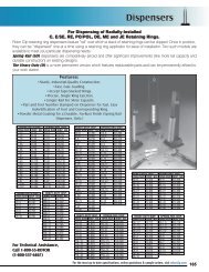
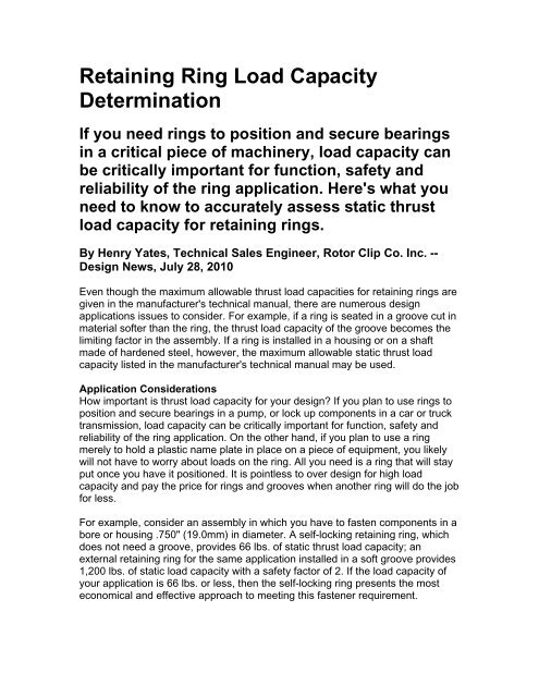
<strong>Retaining</strong> <strong>Ring</strong> <strong>Load</strong> <strong>Capacity</strong><strong>Determination</strong>If you need rings to position and secure bearingsin a critical piece of machinery, load capacity canbe critically important for function, safety andreliability of the ring application. Here's what youneed to know to accurately assess static thrustload capacity for retaining rings.By Henry Yates, Technical Sales Engineer, <strong>Rotor</strong> <strong>Clip</strong> Co. Inc. --Design News, July 28, 2010Even though the maximum allowable thrust load capacities for retaining rings aregiven in the manufacturer's technical manual, there are numerous designapplications issues to consider. For example, if a ring is seated in a groove cut inmaterial softer than the ring, the thrust load capacity of the groove becomes thelimiting factor in the assembly. If a ring is installed in a housing or on a shaftmade of hardened steel, however, the maximum allowable static thrust loadcapacity listed in the manufacturer's technical manual may be used.Application ConsiderationsHow important is thrust load capacity for your design? If you plan to use rings toposition and secure bearings in a pump, or lock up components in a car or trucktransmission, load capacity can be critically important for function, safety andreliability of the ring application. On the other hand, if you plan to use a ringmerely to hold a plastic name plate in place on a piece of equipment, you likelywill not have to worry about loads on the ring. All you need is a ring that will stayput once you have it positioned. It is pointless to over design for high loadcapacity and pay the price for rings and grooves when another ring will do the jobfor less.For example, consider an assembly in which you have to fasten components in abore or housing .750" (19.0mm) in diameter. A self-locking retaining ring, whichdoes not need a groove, provides 66 lbs. of static thrust load capacity; anexternal retaining ring for the same application installed in a soft groove provides1,200 lbs. of static load capacity with a safety factor of 2. If the load capacity ofyour application is 66 lbs. or less, then the self-locking ring presents the mosteconomical and effective approach to meeting this fastener requirement.
A self-locking retaining ring (left) retains the end cap on the shaft of this window blind.Since the application generates less than 66 lb. of static thrust load capacity, the ringdoes not require a groove; in contrast, the gear application (right) requires a standardexternal ring installed in a groove in order to accommodate greater thrust loads andRPMs than the blind application.The bottom line here is that paying close attention to load capacity requirementsbefore making any ring selections can save costs in this stage of your design.<strong>Ring</strong> Thrust <strong>Load</strong>sFor maximum thrust capacity in both static and dynamic loading, the abuttingface of the retained part should have a square corner. Fit of the retained part inthe housing or on a shaft should allow reasonably concentric uniform loadingagainst the ring.When there is radial play between the retained part and the shaft or housing,such play must be treated as though the retained part had a chamfered corner.The magnitude of the chamfer should be considered equal to the play. Therefore,
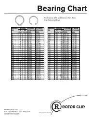
loading data for rings abutted by chamfered parts as shown in the specificmanufacturer's ring data charts must be considered.Allowable load capacities for rings apply only to standard thickness rings made ofstandard materials using the shear strength values listed in Table 1.When the special materials listed in Table 2 are used, multiply the allowablethrust load of the ring by the conversion factor shown.Groove Thrust <strong>Load</strong>s
The allowable thrust loads listed for rings used in grooves are based upon ahousing or shaft material of cold rolled steel with a tensile yield strength of45,000 psi. In the case of beveled retaining rings, the values given in Table 3 arefor minimum contact between ring and groove-i.e., engagement of the bevelededge of the ring with the beveled groove wall at a length equal to half of thegroove depth (d/2).When the following materials are used, multiply the allowable thrust load of thegroove by the conversion factor shown in Table 3.For more information about <strong>Rotor</strong> <strong>Clip</strong>, visit: http://www.rotorclip.com