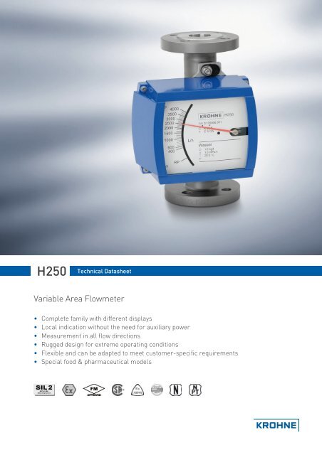
Variable Area Flowmeter
Variable Area Flowmeter
Variable Area Flowmeter

You also want an ePaper? Increase the reach of your titles
YUMPU automatically turns print PDFs into web optimized ePapers that Google loves.
H250 nnnnnnnnnnnnnnnnnnnnnnnnnnnnnnnnnnnnnnnnnnnnnnnnnnnTechnical dataApplication rangeFlow measurement of liquids, gases and vaporsFunction / measuring principleSuspended solid particle measuring principleMeasuring accuracy H250 /RR /HC /F ± 1.6% acc. to directive VDI / VDE 3513, sheet 2Measuring accuracy H250/C (ceramic/PTFE) ± 2.5% acc. to directive VDI / VDE 3513, sheet 2Inlet run≥ 5 x DNOutlet run≥ 3 x DNOperating pressure PS up to 3000 bar per directive 97/23/ EC, April 29, 1999Test pressure PTper pressure equipment directive 97/23/EC or AD 2000-HP30Min. required operating pressureSuspended solid particle decrease during gas measurement recommended:DN15 / ½"DN25 / 1"DN50 / 2"DN80 / 3"DN100 / 4"Twice as great as pressure loss (see measuring ranges)Operating pressure less than 0.3 barOperating pressure less than 0.3 barOperating pressure less than 0.2 barOperating pressure less than 0.2 barOperating pressure less than 0.2 barNominal sizes, DINBoltsTightening torquesNominal sizes as per EN 1092-1 Quantity x size SI [Nm] Imp [lb-ft]DN15 PN40 4 x M12 9.8 7.1DN25 PN40 4 x M12 21 15DN50 PN40 4 x M16 57 41DN80 PN16 8 x M16 47 34DN100 PN16 8 x M16 67 48Nominal sizes, ASMEBoltsTightening torquesNormal sizes as per ASME B 16.5 Quantity x size SI [Nm] Imp [lb-ft]½" 150 lbs / 300 lbs 4 x ½" 5.2 3.81" 150 lbs / 300 lbs 4 x ½" 10 7.22" 150 lbs / 300 lbs 4 x 5/8" 41 303" 150 lbs / 300 lbs 4 x 5/8" 70 514" 150 lbs / 300 lbs 8 x 5/8" 50 364www.krohne.com
nnnnnnnnnnnnnnnnnnnnnnnnnnnnnnnnnnnnnnnnnnnnnnnnnn H250WeightsWeights [kg] H250 with heating H250/CScrewconnectionNominaldiameter EN 1092-1 Flange connectionErmeto 12connection EN 1092-1ASME B 16.5 /150 lbsASME B 16.5 /300 lbs DIN 11864-1DN15 / ½" 3.5 5.55 5.7 3.5 3.2 3.5 2DN25 / 1" 5 7.45 7.6 5 5.2 6.8 3.5DN50 / 2" 8.2 11.15 11.3 10 10 11 5DN80 / 3" 12.2 14.75 14.9 13 13 15 7.6DN100 / 4" 14 17.35 17.5 15 16 17 10.3Process connectionsStandards Connection dimensions Pressure ratingFlange (H250/RR /HC /C) EN-1092-1 DN15...DN100 PN16...PN100ASME B16.5 1/2"...4" 150 lbs...600 lbsJIS B 2238 LR15…LR100 10K...20KClamp connections (H250/RR /F) DlN 32676 DN15...DN100 10 bar...16 barISO 2852 Size 25...139.7 10 bar...16 barThreaded connections (H250/RR /HC /F) DIN 11851 DN15...DN100 25 bar...40 barSMS 1146 1"...4" 6 barInside thread welded (H250/RR /HC) ISO 228 G1/2"...G2" PN50ASME B1.20.11/2"…2" NPTInside thread, screwed (H250/RR /HC) ISO 228 G1/2"…2" PN40...PN50with insert and union nut ASME B1.20.1 1/2"…2" NPTAseptic threaded connection (H250/F) DIN 11864 - 1 DN15…DN50 PN40- DN80…DN100 PN16Aseptic flange (H250/F) DIN 11864 - 2 DN15…DN50 PN40- DN80…DN100 PN16Meters (H250/RR /HC) with heating: EN 1092-1 DN15 PN40Heating with flange connection ASME B16.5 1/2" 150 lbs / RFHeating with pipe connection for Ermeto - E12 PN40Higher pressure ratings and other connection on requestwww.krohne.com 5
H250 nnnnnnnnnnnnnnnnnnnnnnnnnnnnnnnnnnnnnnnnnnnnnnnnnnnMaterialsRR - stainless steel, HC - Hastelloy, C - ceramic/PTFE, F - foodDevice Measuring tube Flanges / raised face Suspended solid particle Receiver / guide Circular orificeH250/RR CrNi steel 1.4404 1 CrNi steel 1.4404 CrNi steel 1.4404 1 CrNi steel 1.4404 1 -massive 1H250/HC Hastelloy C4 (2.4610) CrNi steel 2.4610 withHastelloy C4 (2.4610)plated 1H250/C 2CrNi steel 1.4571 withPTFE liner 3CrNi steel 1.4571 withPTFE liner 3Hastelloy C4 (2.4610) Hastelloy C4 (2.4610) -HC4, PTFE or Al2O3 with Al2O3 and PTFEseal: Kalrez KLR 6375 4H250/F 5 CrNi steel 1.4435 CrNi steel 1.4435 CrNi steel 1.4435 CrNi steel 1.4435 -1 deliverable on request CrNi steel 1.4571, with clamp connections CrNi steel 1.44352 DN100 / 4" only PTFE3 PTFE-TFM (electrically nonconductive)4 Gasket 2035 (Kalrez) or 40795 wetted surfaces Ra ≤ 0.8 μmAl2O3Further options:• Special material on request: e.g. SMO 254, Titan, 1.4435• Suspended solid particle decrease: ceramic or PEEK• Seal for devices with internal thread: O-ring FPM / FKM6www.krohne.com
nnnnnnnnnnnnnnnnnnnnnnnnnnnnnnnnnnnnnnnnnnnnnnnnnn H250Technical data for indicators M8 M9 M10Indicator M8M8M limit switchClamp connection 2.5mm 2Limit switches SC3,5-N0-Y SJ3,5-SN SJ3,5-S1NType 2-wire NAMUR 2-wire NAMUR 2-wire NAMURSwitch configuration Normally closed Normally closed Normally openNominal voltage U0 8 VDC 8 VDC 8 VDCPointer shaft not read ≥3 mA ≥3 mA ≤1 mAPointer shaft read ≤1 mA ≤1 mA ≥3 mAM8E current outputCable gland M16 x 1.5Pipe diameter8…10 mmClamp-type terminal 4 mm 2Measuring signal 4...20 mA for 0...100% flow value Two-wire technologyPower supply14.8...30 Volt DCMin. power supply at HART TM20.5 VdcPower supply effect < 0.1%Input impedance dependence < 0.1%Temperature effectMax. input impedance / loadMin. load at HART TM< 10uA / K640 Ohm (30VDC)250 OhmM8E HARTM8E HART TM ParameterizationManufacturer's name (code) KROHNE Messtechnik (69)Model name M8E (230)HART TM Protocol revision 5.1Device revision 1Physical layerDevice categoryFSKTransmitterM8E process variableM8E process variable flowrate Values [%] Signal output [mA]Over range +105 (± 1%) 20.64...20.96Device error identification > 110 > 21.60Maximum 112.5 22Multi drop operation - 4.5www.krohne.com 7
H250 nnnnnnnnnnnnnnnnnnnnnnnnnnnnnnnnnnnnnnnnnnnnnnnnnnnIndicator M9M9 cable fittingCable fitting Material Cable diameterM 16x1.5 Standard PA 5...10 mmM 20x1.5 PA 8...13 mmM 16x1.5 Nickel-plated brass 5...9 mmM 20x1.5 Nickel-plated brass 10...14 mmM9 limit switchesClamp connection 2.5mm 2Limit switches SC3,5-N0-Y SJ3,5-SN SJ3,5-S1N SB3,5-E2Type 2-wire NAMUR 2-wire NAMUR 2-wire NAMUR 3-wireSwitch configuration Normally closed Normally closed Normally open PNP normally openNominal voltage U0 8 V 8 V 8 V 10...30 VPointer shaft not read ≥3 mA ≥3 mA ≤1 mA ≤ 0.3 VPointer shaft read ≤1 mA ≤1 mA ≥3 mA Vb - 3 VContinuous current - - - max. = 100 mANo-load current I0 - - - ≤15 mAM9 current output ESK2AClamp connection 2.5 mm 2Power supply12...30 VDCMeasurement signal 4.00...20.00 mA for 0...100% flow value Two-wire technologyPower supplyMin. power supply for HART TM12...30 VDC18 VDCEffect of supply power < 0.1%External resistance dependence < 0.1%Temperature influenceMax. external resistance / load impedanceMin. load with HART TM< 5 mA / K800 ohms (30 VDC)250 ohmsM9 ESK2A HARTESK2A HART TM parameter configurationName of manufacturer (code) KROHNE Messtechnik (69 = 45h)Name of modelESK2A (226 = E2h)HART TM protocol revision 5.9Device revision 1Physical layerFSKDevice categoryTransmitter non dc isolated deviceM9 ESK2A process variableESK2A process variable flow rate Values [%] Signal output [mA]Over range +102.5 (± 1%) 20.24...20.56Device error detection > 106.25 > 21.00Maximum 131.25 25Multi-drop operation - 4.5Lift-off voltage12 VDC8www.krohne.com
nnnnnnnnnnnnnnnnnnnnnnnnnnnnnnnnnnnnnnnnnnnnnnnnnn H250M9 ESK totalizerClamp connection 2.5 mm 2Power supply10...30 VDCR ext. Current loop0...600 ohmsPower consumptionmax. 2.5 wattsMax. external resistance / load impedance 720 ohms depending on power supplyIndicating error < 1% maximum one scalar unitMax. reset voltage30 VDCMin. reset pulse20 ms.Power supply10...30 VDCMax. current50 mAMax. dissipation250 mWT on 80 ms fixed pulse widthT offdepends on flow rateV onVb – 3 voltsV off0 voltsPulse value 1 pulse = 1 display totalizer advance = 1 flow unit (1 liter, 1 m 3 ...)M9 ESK3PAClamp connection 2.5mm 2Bus cable R´Bus cable L´Bus cable C´15...150 ohms/km0.4...1 NH/km80...200 nF/km.M9 ESK3PA hardwareHardwareaccording to IEC 1158-2 and FISCO modelPower supply9...32 VDCBase current12 mAStarting current< Base currentFDE< 18 mAAccuracy as per VDI/ VDE 3513 1.6Measurement resolution< 0.1 % of full-scale valueTemperature influence< 0.05 % / K of full-scale valuewww.krohne.com 9
H250 nnnnnnnnnnnnnnnnnnnnnnnnnnnnnnnnnnnnnnnnnnnnnnnnnnnM9 ESK3PA softwareSoftwareGSDDevice master fileDevice profile Profiles B, V3.0Function blocksFlow rate (A10)Volume or massTotalizer (TOT0) Volume totalizer Default units: [m3]Totalizer (TOT1) Mass totalizer Default units: [kg]Address range 0...126, default 126SAP'sService_Access_PointsDDDevice descriptionIndicator M10M10 indicatorCable fitting none (standard)M 20x1.5on requestM 20x1.5 Ex don requestM10 current outputcurrent outputTwo-wire technologyPower supply 24 VDC +/- 30Signal output current4...20 mAEffect of supply power < 0.1External resistance dependence < 0.1Temperature influence< 5 uA/KExternal resistance / load impedance≤ 630 ohmsExternal resistance with HART≥ 250 ohmsM10 HARTName of manufacturer (code) KROHNE Messtechnik (69)Name of modelM10AHART TM protocol revision 5.1Device revision 1Physical layerFSKDevice categoryTransmitterM10 process variableValues [%]Signal output [mA]Over range +105 (± 1%) 20.64...20.96Device error detection > 110 > 21.60Maximum 112.5 22Multi-drop operation - 4.5M10 digital outputBinary outputsgalvanically isolatedOperating mode Binary output NAMUR or open collectorconfigurable as switching contact normally open / normally closed orpulse outputmax. 10 pulses per secondNAMUR binary outputPower supply8 VSignal current> 3 mA if switching value not reached;10www.krohne.com
nnnnnnnnnnnnnnnnnnnnnnnnnnnnnnnnnnnnnnnnnnnnnnnnnn H250Open collector binary outputPower supplyPmaxImax< 1 mA when switching value reached8...30 VDC500 mW100 mAM10 reset inputBinary inputOperating modeconfigurable asVoltage levelCurrent drawnPulse length (active)galvanically isolatedCounter resetactive HI / active LO5...30 VDC≤1 mA≥ 500 mswww.krohne.com 11
H250 nnnnnnnnnnnnnnnnnnnnnnnnnnnnnnnnnnnnnnnnnnnnnnnnnnnDimensionsDimensions of H250/M9H250/M9 H250/M9 H250 with heating H250/HT high-temperatureDimensions [mm]a b c d e Ø f g h jDN15 PN40 138 250 110.5 181 107 20 100 150 187DN25 PN40 138 250 110.5 181 119 32 106 150 199DN50 PN40 138 250 123.5 181 132 65 120 150 212DN80 PN40 138 250 123.5 181 148 89 160 150 228DN100 PN40 138 250 123.5 181 158 114 150 150 232Installation height of H250/C (ceramic/PTFE) from 3"/300 lbs: 300 mmInstallation height of H250/F (food) with threaded connection per ISO 228 with internal thread: 300 mm12www.krohne.com
nnnnnnnnnnnnnnnnnnnnnnnnnnnnnnnnnnnnnnnnnnnnnnnnnn H250Dimensions of H250/M10 /M8H250/M10 H250/M10 H250/M8 H250/M8M10 dimensions [mm] M8M dimensions [mm] M8E dimensions [mm]a b c d e f g h f g hDN15 PN40 147 83 118 Ø 132 55 63 60 58.5 53.5 66 52.5DN25 PN40 147 83 130 Ø 132 55 75 60 58.5 65.5 66 52.5DN50 PN40 147 83 143 Ø 132 55 89 73 45.5 79.5 79 39.5DN80 PN40 147 83 160 Ø 132 55 105 73 45.5 95.5 79 39.5DN100 PN40 147 83 169 Ø 132 55 114 73 45.5 104.5 79 39.5www.krohne.com 13
H250 nnnnnnnnnnnnnnnnnnnnnnnnnnnnnnnnnnnnnnnnnnnnnnnnnnnMeasuring rangesH250/RR - stainless steel, H250/HC - HastelloyMeasuring span 10 : 1Flow values 100%H250/RR, H250/HC,H250/FNominaldiameterWater Air Max. pressure lossFloat TIV CIV DIV TIV (Alu) TIV DIV TIV Alu TIV CIV DIVCone [l/h] [l/h] [l/h] [m3/h] [m3/h] [m3/h] [mbar] [mbar] [mbar] [mbar]DN15 1/2" K 15.1 18 25 - 0.42 0.7 - 12 21 26 -K 15.2 30 40 - 0.7 1 - 12 21 26 -K 15.3 55 63 - 1 1.5 - 12 21 26 -K 15.4 80 100 - 1.7 2.2 - 12 21 26 -K 15.5 120 160 - 2.5 3.6 - 12 21 26 -K 15.6 200 250 - 4.2 5.5 - 12 21 26 -K 15.7 350 400 700 6.7 10 18 1 12 21 28 38K 15.8 500 630 1000 10 14 28 1 13 22 32 50K 15.8 - - 1600 2 - - 50 2 - - - 85DN25 1" K 25.1 480 630 1000 9.5 14 - 11 24 32 72K 25.2 820 1000 1600 15 23 - 11 24 33 74K 25.3 1200 1600 2500 22 35 - 11 25 34 75K 25.4 1700 2500 4000 37 50 110 1 12 26 38 78K 25.5 3200 4000 6300 62 95 180 1 13 30 45 103 3DN50 2" K 55.1 2700 6300 8400 58 80 230 1 8 13 74 60K 55.2 3600 10000 1400 77 110 350 1 8 13 77 69K 55.3 5100 16000 25000 110 150 700 1 9 13 84 104DN80 3" K 85.1 12000 25000 37000 245 350 1000 1 8 16 68 95K 85.2 16000 40000 64000 280 400 1800 1 9 16 89 125DN100 4" K105.1 19000 63000 100,000 - 550 2800 1 - - 120 2201 P > 0.5 bar2 with TR float3 300 mbar with damping (gas measurement)Reference condition:Water 20°CAir 20°C - 1.013bar abs.Notes:• Air measurement - TIV suspended solid particles: Heating not possible• The indicated pressure losses apply for water and air at maximum flow.• Other flow rate measuring ranges can be provided upon request.• The conversion of other process fluids or operating data (pressure, temperature, density, viscosity) is doneat KROHNE with the help of the calculation procedure as detailed in VDE /VDI Directive 351314www.krohne.com
nnnnnnnnnnnnnnnnnnnnnnnnnnnnnnnnnnnnnnnnnnnnnnnnnn H250H250/C - Ceramic/PTFEMeasuring span 10 : 1Flow values 100%NominaldiametersH250/C Flow Max. pressure lossWater Air Water AirLiner / float PTFE Ceramic Ceramic PTFE Ceramic CeramicCone [l/h] [l/h] [m3/h] [mbar] [mbar] [mbar]DN15, 1/2" E 17.2 25 30 - 65 62 62E 17.3 40 50 1.8 66 64 64E 17.4 63 70 2.4 66 66 66E 17.5 100 130 4 68 68 68E 17.6 160 200 6.5 72 70 70E 17.7 250 250 9 86 72 72E 17.8 400 - - 111 - -DN25, 1" E 27.1 630 500 18 70 55 55E 27.2 1000 700 22 80 60 60E 27.3 1600 1100 30 108 70 70E 27.4 2500 1600 50 158 82 82E 27.5 4000 1 2500 75 290 100 100DN50, 2" E 57.1 4000 4500 140 81 70 70E 57.2 6300 6300 200 110 80 80E 57.3 10000 11000 350 170 110 110E 57.4 16000 1 - - 284 - -DN80, 3" E 87.1 16000 16000 - 81 70 -E 87.2 25000 25000 - 95 85 -E 87.3 40000 1 - - 243 - -DN100, 4" E 107.1 40000 - - 100 - -1 special floatE 107.2 60000 1 - - 225 - -Reference condition:Water 20°CAir 20°C - 1.013bar abs.Notes:• The indicated pressure losses apply for water and air at maximum flow.• Other flow rate measuring ranges can be provided upon request.• The conversion of other process fluids or operating data (pressure, temperature, density, viscosity) is doneat KROHNE with the help of the calculation procedure as detailed in VDE /VDI Directive 3513www.krohne.com 15
H250 nnnnnnnnnnnnnnnnnnnnnnnnnnnnnnnnnnnnnnnnnnnnnnnnnnnH250H - horizontal installationMeasuring span 10 : 1Flow values 100%Suspended solidparticle shape Cone no. Flow, water [l/h] Pressure loss [mbar]Spring A Spring B Spring A Spring BDN15 DIV TB K 15.1 70 195K 15.2 120 204K 15.3 180 195K 15.4 280 225K 15.5 450 250K 15.6 700 325K 15.7 1200 590K 15.8 1600 2400 950 1600DN25 DIV T K 25.1 1300 122K 25.2 2000 105K 25.3 3000 116K 25.4 5000 145K 25.5 8500 10000 217 336DN50 DIV T K 55.1 10000 240K 55.2 16000 230K 55.3 22000 34000 220 420DN80 DIV T K 85.1 25000 130K 85.2 35000 60000 130 290DN100 DIV L K 105.1 80000 120000 250 340Reference condition:Water 20°CNotes:• The indicated pressure losses apply for water at maximum flow.• Other flow rate measuring ranges can be provided upon request.• Conversion of other process fluids or operating data as detailed in VDE /VDI Directive 351316www.krohne.com
nnnnnnnnnnnnnnnnnnnnnnnnnnnnnnnnnnnnnnnnnnnnnnnnnn H250H250U - vertical installation - direction of flow from top downMeasuring span 10 : 1Flow values 100%Suspended solid particleshape Cone no. Flow, water [l/h] Pressure loss [mbar]DN15 DIV TB K 15.1 65 175K 15.2 110 178K 15.3 170 180K 15.4 260 200K 15.5 420 220K 15.6 650 290K 15.7 1100 520K 15.8 1500 840DN25 DIV T K 25.1 1150 97K 25.2 1800 85K 25.3 2700 92K 25.4 4500 115K 25.5 7600 172DN50 DIV T K 55.1 9000 220K 55.2 15000 230K 55.3 21000 240Reference condition:Water 20°CNotes:• The indicated pressure losses apply for water at maximum flow.• Other flow rate measuring ranges can be provided upon request.• Conversion of other process fluids or operating data as detailed in VDE /VDI Directive 3513www.krohne.com 17
H250 nnnnnnnnnnnnnnnnnnnnnnnnnnnnnnnnnnnnnnnnnnnnnnnnnnnTemperatures H250/M9 - mechanical display without power supplySuspended solid particle Liner Measuring temp. [°C] Ambient temp. [°C]H250/RR Stainless steel Stainless steel +300H250/HC Hastelloy C4 Hastelloy C4 +300H250/C PTFE PTFE +70 +70H250/C Ceramic PTFE +150 +70H250/C Ceramic TFM +250 +120H250H - H250U +100Min. temperature of mediumStandard -196H250H H250U -40Ambient temperaturesStandard -40...+120Screw fitting-20…+120H250H H250U-20…+90Temperatures H250/M9 - with electrical componentsTS °C (Tamb.
nnnnnnnnnnnnnnnnnnnnnnnnnnnnnnnnnnnnnnnnnnnnnnnnnn H250Temperatures H250 /M8 /M10M8MMax. Tmed. at Tamb. +60°C +200Min. measuring temperature TS without limit monitor -80Min. measuring temperature TS with limit monitor -25Max. ambient temperature Tamb. +70Min. ambient temperature Tamb. -25M8EMax. Tmed. at Tamb. +40°C +200Max. Tmed. at Tamb. +50°C +185Max. Tmed. at Tamb. +60°C +145Min. Tmed. -25Max. ambient temperature Tamb. +70Min. ambient temperature Tamb. -25M10Max. Tmed. at Tamb. +60°C +200Min. measuring temperature TS -80Max. ambient temperature Tamb. +75Min. ambient temperature Tamb. -40www.krohne.com 19
H250 nnnnnnnnnnnnnnnnnnnnnnnnnnnnnnnnnnnnnnnnnnnnnnnnnnnKROHNE Product Overview• Electromagnetic flowmeters• <strong>Variable</strong> area flowmeters• Mass flowmeters• Ultrasonic flowmeters• Vortex flowmeters• Flow controllers• Level measuring instruments• Pressure gauges• Temperature measuring instruments• Water solutions & analysis• Oil and gas turnkey solutionsAddresses:© KROHNE 01/2007 7.02312.27.00 Subject to change without noticeGermanyNorthern sales officeKROHNE Messtechnik GmbH & Co. KGBremer Str. 133D-21073 HamburgPhone:+49 (0)40 767 3340Fax:+49 (0)40 767 33412nord@krohne.deZIP code: 10000 - 29999, 49000 - 49999Western and middle sales officeKROHNE Messtechnik GmbH & Co. KGLudwig-Krohne-StraßeD-47058 DuisburgPhone:+49 (0)203 301 416Fax:+49 (0)203 301 10416west@krohne.deZIP code: 30000 - 34999, 37000 -48000, 50000 - 53999, 57000 - 59999,98000 - 99999Southern sales officeKROHNE Messtechnik GmbH & Co. KGLandsberger Str. 392D-81241 MunichPhone:+49 (0)89 121 5620Fax:+49 (0)89 129 6190sued@krohne.deZIP code: 0 - 9999, 80000 - 89999,90000 - 97999Southwestern sales officeKROHNE Messtechnik GmbH & Co. KGRüdesheimer Str. 40D-65239 Hochheim/MainPhone: +49(0)6146) 827 30Fax:+49 (0)6146 827 312rhein-main@krohne.deZIP code: 35000 - 36999, 54000 -56999, 60000 - 79999Instrumentation and controlequipment catalogTABLAR Messtechnik GmbHLudwig-Krohne-Straße 5D-47058 DuisburgPhone:+49 (0)2 03 305 880Fax:+49 (0)2 03 305 8888kontakt@tablar.de www.tablar.deKROHNE salescompaniesInternationalAustraliaKROHNE Australia Pty LtdQuantum Business Park 10/287Victoria Rd Rydalmere NSW 2116Phone: +61 2 8846 1700Fax: +61 2 8846 1755krohne@krohne.com.auAustriaKROHNE Austria Ges.m.b.H.Modecenterstraße 14A-1030 ViennaPhone:+43 (0)1/203 45 32Fax:+43 (0)1/203 47 78info@krohne.atBelgiumKROHNE Belgium N.V.Brusselstraat 320B-1702 Groot BijgaardenPhone:+32 (0)2 4 66 00 10Fax:+32 (0)2 4 66 08 00krohne@krohne.beBrazilKROHNE Conaut ControlesAutomaticos Ltda.Estrada Das Águas Espraiadas, 230C.P. 56 06835 - 080 EMBU - SPPhone:+55 (0)11-4785-2700Fax:+55 (0)11 4785-2768conaut@conaut.com.brChinaKROHNE Measurement Instruments(Shanghai) Co. Ltd., (KMIC)Room 15011033 Zhaojiabang RoadShanghai 200030Phone: +86 21 6487 9611Fax:+86 21 6438 7110info@krohne-asia.comCzech RepublicSobìsická 15663800 BrnoPhone: +420 (0)545.242 627Fax: +420 (0)545 220 093brno@krohne.czFranceKROHNE S.A.S.Les Ors BP 98F-26103 ROMANS CedexPhone:+33 (0)4 75 05 44 00Fax:+33 (0)4 75 05 00 48info@krohne.frGreat BritainKROHNE Ltd.Rutherford DrivePark Farm Industrial EstateWellingboroughNorthants NN8 6AEPhone:+44 (0)19 33 408 500Fax:+44 (0)19 33 408 501info@krohne.co.ukCISKanex KROHNE Engineering AGBusiness-Centre PlanetaOffice 404 ul.Marxistskaja 3109147 Moscow/RussiaPhone:+7 (0)095 911 7165Fax:+7 (0)095 742 8873krohne@dol.ruIndiaKrohne Marshall Ltd.A-34/35, M.I.D.C. Industrial <strong>Area</strong>,H-BlockPimpri Poona 411018Phone:+91 (0)202 744 2020Fax:+91 (0)202 744 2020pcu@vsnl.netIranKROHNE Liaison OfficeNorth Sohrevardi Ave. 26,Sarmad St., Apt. #9Tehran 15539Phone: +9821 8874 5973Fax: +9821 8850 1268krohne@krohneiran.comItalyKROHNE Italia Srl.Via V. Monti 75I-20145 MilanPhone:+39 02 4300 661Fax:+39 02 4300 6666info@krohne.itKoreaKROHNE KoreaRoom 508 Miwon Bldg 43Yoido-Dong Youngdeungpo-KuSeoul, KoreaPhone: 00-82-2-782-1900Fax: 00-82-2-780-1749krohnekorea@krohnekorea.comNetherlandsKROHNE Nederland B.V.Kerkeplaat 14NL-3313 LC DordrechtPhone:+31 (0)78 630 6200Fax:+31 (0)78 630 6405Service Direct: +31 (0)78 630 6222info@krohne.nlNorwayKROHNE Norway A.S.Ekholtveien 114NO-1521 MossPhone:+47 (0)69 264 860Fax:+47 (0)69 267 333postmaster@krohne.noPolandKROHNE Polska Sp.z.o.o.ul. Stary Rynek Oliwski 8a80-324 GdanskPhone: +48 (0)58 520 9211Fax.:+48 (0)58 520 9212info@krohne.plSwitzerlandKROHNE AGUferstr. 90CH-4019 BaselPhone:+41 (0)61 638 30 30Fax:+41 (0)61 638 30 40info@krohne.chSingaporeTokyo Keiso - KROHNE (Singapore)Pte. Ltd.14, International Business Park,Jurong EastChiyoda Building, #01-01/02Singapore 609922Phone: (65) 6567 4548Fax : (65) 6567 9874tks@tokyokeiso-krohne.com.sgRepublic of South AfricaKROHNE Pty. Ltd.Bushbock CloseCorporate Park SouthMidrand, GautengP.O. Box 2069Midrand, 1685Phone: +27 (0)11 314 1391Fax: +27 (0)11 314 1681midrand@krohne.co.zaSpainI.I. KROHNE IBERIA, S.r.l.Poligono Industrial NiloCalle Brasil, nº. 528806 Alcalá de Henares MadridPhone: +34 (0)91 883 2152Fax: +34 (0)91 883 4854krohne@krohne.esUSAKROHNE, Inc.7 Dearborn RoadPeabody, MA 01960Phone: +1 (800) FLOWINGPhone: +1 (978) 535 6060 (in MA)info@krohne.comRepresentativesAlgeriaArgentinaCameroonCanadaChileColumbiaCroatiaDenmarkEcuadorEgyptFinlandGabonGhanaGreeceHong KongHungaryIndonesiaIranIrelandIsraelIvory CoastJapanJordanKuwaitLibyaLithuaniaMalaysiaMauritiusMexicoMoroccoNew ZealandPeruPortugalRomaniaSaudi ArabiaSenegalSlovakiaSloveniaSwedenTaiwanThailandTunisiaTurkeyVenezuelaYugoslaviaOther countriesKROHNE Messtechnik GmbH & Co. KGLudwig-Krohne-Str. 5D-47058 DuisburgPhone:+49 (0)203 301 0Fax:+49 (0)203 301 389export@krohne.dewww.krohne.com