CITOLINE - Oerlikon, the expert for industrial welding
CITOLINE - Oerlikon, the expert for industrial welding
CITOLINE - Oerlikon, the expert for industrial welding

Create successful ePaper yourself
Turn your PDF publications into a flip-book with our unique Google optimized e-Paper software.
2333-001<br />
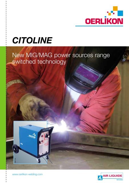
<strong>CITOLINE</strong><br />
New MIG/MAG power sources range<br />
switched technology<br />
2007-125<br />
www.oerlikon-<strong>welding</strong>.com
2<br />
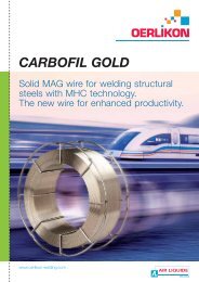
<strong>CITOLINE</strong>: simplicity and efficiency<br />
Helmet/mask<br />
Protective<br />
clothing<br />
Earth<br />
clamp<br />
2003-390<br />
Fume extraction<br />
Torch<br />
Earth cable<br />
Primary power supply cable connection:<br />
Single-phase 230 V = connection between phase and neutral<br />
400 V = connection between 2 phases<br />
Three-phase 400 V = connection between 3 phases<br />
230 V = connection between 3 phases<br />
230 V three-phase only exists in certain companies that have<br />
<strong>the</strong>ir own trans<strong>for</strong>mer.<br />
Remote<br />
control<br />
Pressure regulator-flowmeter<br />
Gas<br />
bottle<br />
Cooling unit<br />
Power source<br />
The MIG (Metal Inert Gas) and MAG (Metal Active Gas)<br />
<strong>welding</strong> implement an electric arc under gaseous protection<br />
(inert gas: Argon+CO2).<br />
The wire that constitutes <strong>the</strong> consumable electrode is<br />
continuously unrolled in <strong>the</strong> electric arc and is deposited in<br />
<strong>the</strong> molten metal.<br />
MIG <strong>welding</strong> glossary<br />
CE European standards<br />
They warranty quality, electrical and<br />
mechanical characteristics and <strong>the</strong><br />
safety level of an equipment.<br />
The <strong>Oerlikon</strong> power sources are<br />
certified CE.<br />
These standards define manufacturing<br />
according to 2 directives:<br />
• 89/336/CEE relative to <strong>the</strong><br />
electro-magnetic compatibility (CEM),<br />
which imposes limitation in <strong>the</strong><br />
electro-magnetic disturbance<br />
respecting <strong>the</strong> EN 50 199 standard.<br />
• BT 73/23/CEE relative to <strong>the</strong> safety<br />
rules <strong>for</strong> <strong>welding</strong> equipments<br />
respecting <strong>the</strong> EN 60 974-1 standard.<br />
Protection Class IP<br />
The first digit indicates <strong>the</strong> maximum<br />
diameter of an object to be introduced<br />
inside <strong>the</strong> equipment and that could<br />
come into contact with an element<br />
under dangerous tension.<br />
Welding operation<br />
Torch<br />
Nozzle<br />
Contact tip<br />
Gaseous protection<br />
Molten metal<br />
The second digit indicates <strong>the</strong><br />
protection level against falling rain.<br />
Ex: IP 23 (<strong>the</strong> 2 means that an object of<br />
12.5 mm diameter can be introduced in<br />
<strong>the</strong> device, <strong>the</strong> 3 means that it is<br />
protected against falling ain up to a<br />
maximum angle of 60°).<br />
2 times mode<br />
The <strong>welding</strong> occurs by pulling <strong>the</strong><br />
torch's trigger.<br />
It stops by loosening <strong>the</strong> trigger.<br />
Classical 4 times mode<br />
The pre-gas occurs by pushing <strong>the</strong><br />
trigger, afterwards <strong>the</strong> <strong>welding</strong> starts by<br />
loosening it <strong>the</strong>n with <strong>the</strong> next push on<br />
<strong>the</strong> trigger <strong>the</strong> <strong>welding</strong> stops and <strong>the</strong><br />
post-gas stays active until releasing <strong>the</strong><br />
trigger.<br />
Electrode<br />
wire<br />
Gaseous<br />
protection<br />
Electrode wire<br />
(final part)<br />
Weld bead<br />
Contact<br />
tip<br />
Electric<br />
arc<br />
Spot mode<br />
The power source starts to weld when<br />
<strong>the</strong> trigger is pushed, but <strong>the</strong> <strong>welding</strong><br />
stops automatically after a pre-set<br />
delay.<br />
Intermittance mode<br />
This is a point mode which is<br />
repeatable. If <strong>the</strong> push on <strong>the</strong> trigger is<br />
maintained, <strong>the</strong> <strong>welding</strong> will be retaken<br />
after an o<strong>the</strong>r delay which is as well to<br />
be regulated.<br />
Duty cycle<br />
It is defined in <strong>the</strong> standard<br />
EN 60974-1. It corresponds to <strong>the</strong><br />
continuous use of an equipment during<br />
10 minutes at a temperature of 40 °C.<br />
A duty cycle of 100 A at 60%, means<br />
that during 10 minutes, <strong>the</strong> power<br />
source can weld during 6 mn at 100 A<br />
followed by 4 mn of stop.<br />
A duty cycle 100 A at 100% means that<br />
<strong>the</strong> power source can provide<br />
continuously 100 A.
Wide choice <strong>for</strong> a better satisfaction.<br />
The complete <strong>CITOLINE</strong> range was designed with <strong>the</strong> <strong>welding</strong> professional in mind.<br />
The <strong>CITOLINE</strong> range offers an <strong>industrial</strong> solution with a 35% duty cycle making it<br />
ideal <strong>for</strong> maintenance/repair and manufacturing applications. The complete range<br />
and reliability make it one of <strong>the</strong> MIG references in today's market.<br />
Designation Duty cycle Supply Feeding<br />
Steel.<br />
Stainless steel (mm)<br />
Aluminium<br />
(mm)<br />
Cored wire<br />
(mm)<br />
<strong>CITOLINE</strong> 1700 M 140 A (18%) single-phase 2 rollers 0.6 to 1.0 0.8 to 1.0 1.0 No<br />
<strong>CITOLINE</strong> 2000 M 180 A (20%) single-phase 4 rollers 0.6 to 1.0 0.8 to 1.0 1.0 Option<br />
<strong>CITOLINE</strong> 2000 T 200 A (30%) three-phase 4 rollers 0.6 to 1.0 0.8 to 1.0 1.0 Option<br />
<strong>CITOLINE</strong> 2500 M 250 A (30%) single-phase 4 rollers 0.6 to 1.0 0.8 to 1.0 1.0 Option<br />
<strong>CITOLINE</strong> 2500 T 250 A (30%) three-phase 4 rollers 0.6 to 1.0 0.8 to 1.0 1.0 Option<br />
<strong>CITOLINE</strong> 3000 M 300 A (30%) single-phase 4 rollers 0.8 to 1.2 1.0 to 1.2 1.0 to 1.2 Option<br />
<strong>CITOLINE</strong> 3000 T 300 A (35%) three-phase 4 rollers 0.8 to 1.2 1.0 to 1.2 1.0 to 1.2 Yes<br />
<strong>CITOLINE</strong> 3500 T 350 A (35%) three-phase 4 rollers 0.8 to 1.2 1.0 to 1.2 1.0 to 1.2 Yes<br />
<strong>CITOLINE</strong> 2500 MS 250 A (30%) single-phase 4 rollers 0.6 to 1.0 0.8 to 1.0 1.0 Yes<br />
<strong>CITOLINE</strong> 3000 MS 300 A (30%) single-phase 4 rollers 0.8 to 1.2 1.0 to 1.2 1.0 to 1.2 Yes<br />
<strong>CITOLINE</strong> 3000 TS 300 A (35%) three-phase 4 rollers 0.8 to 1.2 1.0 to 1.2 1.0 to 1.2 Yes<br />
<strong>CITOLINE</strong> 3500 TS 350 A (35%) three-phase 4 rollers 0.8 to 1.2 1.0 to 1.2 1.0 to 1.2 Yes<br />
<strong>CITOLINE</strong> 3500 TS (W) 350 A (35%) three-phase 4 rollers 0.8 to 1.2 1.0 to 1.2 1.0 to 1.2 Yes<br />
<strong>CITOLINE</strong> 4500 TS 450 A (35%) three-phase 4 rollers 0.8 to 1.6 1.0 to 1.6 1.0 to 1.6 Yes<br />
<strong>CITOLINE</strong> 4500 TS (W) 450 A (35%) three-phase 4 rollers 0.8 to 1.6 1.0 to 1.6 1.0 to 1.6 Yes<br />
Welding per<strong>for</strong>mance and ergonomy<br />
2007-178<br />
2003-583<br />
Power source:<br />
• Compact and light due to <strong>the</strong><br />
dynamicaly self-adusting power<br />
trans<strong>for</strong>mer technology.<br />
Controlled striking<br />
• Possibility to adjust <strong>the</strong> striking<br />
speed.<br />
• Stick out adjustment.<br />
4 rollers mounting plate:<br />
• Equipped with self-adjusting<br />
pressure idle rollers to improve<br />
feeding quality and avoid<br />
unevenness.<br />
Flexibility<br />
• Reverse polarity <strong>for</strong> gasless<br />
cored wire application<br />
(compact version).<br />
Display<br />
Easy to use<br />
• Inclined front panel<br />
<strong>for</strong> a complete view.<br />
• Wire feeder<br />
with wheels.<br />
• Wire feeder easily storable<br />
on <strong>the</strong> power source.<br />
• Large pivot foot to allow easy<br />
installation of <strong>the</strong> wire feeder.<br />
2007-172<br />
2007-180<br />
3
1881-047<br />
4<br />
<strong>CITOLINE</strong> M: single-phase range.<br />
Basic equipment:<br />
- Digital display depending on model.<br />
- 4 rollers mounting plate (except on <strong>CITOLINE</strong> 1700 M).<br />
- Reverse polarity depending on model.<br />
- Complete <strong>welding</strong> cycle (2T-4T-Spot-Intermittent).<br />
- Ground cable with clamp.<br />
- K 300 depending on model.<br />
Technical characteristics: <strong>CITOLINE</strong> 1700 M <strong>CITOLINE</strong> 2000 M<br />
Power supply 230 V - 1ph 230 V - 1ph<br />
Primary<br />
Frequency 50 - 60 Hz 50 Hz<br />
Consumption at max. current 24 A 32 A<br />
Secondary<br />
No-load voltage<br />
Welding current<br />
18 - 32 V<br />
30 - 170 A<br />
18 -35 V<br />
35 - 180 A<br />
at 100 % 60 A 85 A<br />
Duty cycle at 40 °C<br />
at 60 % 75 A 110 A<br />
at 35 % 140 A (18 %) 180 A (20 %)<br />
Steel 0.6-0.8-(1.0) mm 0.6-0.8-(1.0) mm<br />
Wires diameter<br />
Stainless steel<br />
Flux cored wire<br />
0.8-(1.0) mm<br />
1.0 mm<br />
0.8-(1.0) mm<br />
1.0 mm<br />
Aluminium 0.8-1.0 mm 0.8-1.0 mm<br />
Protection index IP 21 IP 23<br />
Standards EN 60974-1; -10<br />
Insulation classification H<br />
Dimensional characteristics<br />
Dimensions (W x H x L)<br />
Net weight<br />
440 x 670 x 750 mm<br />
39 kg<br />
500 x 870 x 950 mm<br />
52 kg<br />
Wire feed 2 rollers 4 rollers<br />
Digital display No Option W 000 264 869<br />
Number of self position 1<br />
Reverse polarity Yes<br />
To order<br />
Tailor-made<br />
Power source W 000 261 954* W 000 261 963*<br />
Wire feeder<br />
DV 4004 CTL 5 m<br />
DV 4004 CTL 10 m<br />
-<br />
-<br />
-<br />
-<br />
Package** W 000 261 780 W 000 266 707<br />
WELDLINE WMT 15 A WMT 25 A<br />
Torch (air cooled)<br />
length 3 m W 000 010 600 W 000 010 602<br />
length 4 m W 000 010 601 W 000 010 603<br />
Pressure regulator - flowmeter Consult us<br />
* Compact version with integrated wire feeder.<br />
** For French market.<br />
2007-124<br />
2007-166R
2007-169<br />
Compact and separate (S) versions.<br />
2007-169R<br />
SINGLE-PHASE RANGE<br />
<strong>CITOLINE</strong> 2500 M <strong>CITOLINE</strong> 3000 M <strong>CITOLINE</strong> 2500 MS <strong>CITOLINE</strong> 3000 MS<br />
230 V - 1ph 230 V - 1ph 230 V - 1ph 230 V - 1ph<br />
50 Hz 50 Hz 50 Hz 50 Hz<br />
54 A 67 A 54 A 67 A<br />
20 - 53 V 20 - 55 V 20 - 53 V 20 - 55 V<br />
32 - 250 A 28 - 300 A 32 - 250 A 28 - 300 A<br />
140 A 165 A 140 A 165 A<br />
180 A 215 A 180 A 215 A<br />
250 A (30 %) 300 A 250 A (30 %) 300 A<br />
0.8-1.0-(1.2) mm 0.8-1.2 mm 0.8-1.0-(1.2) mm 0.8-1.2 mm<br />
0.8-1.0 mm 0.8-1.2 mm 0.8-1.0 mm 0.8-1.2 mm<br />
1.0 mm 1.0-1.2 mm 1.0 mm 1.0-1.2 mm<br />
0.8-1.0 mm 1.0-1.2 mm 0.8-1.0 mm 1.0-1.2 mm<br />
IP 23<br />
EN 60974-1; -10<br />
H<br />
500 x 870 x 950 mm 500 x 870 x 950 mm 500 x 870 x 950 mm<br />
86 kg 86 kg 86 kg<br />
4 rollers 4 rollers 4 rollers 4 rollers<br />
Option W 000 264 869 Option W 000 264 869 Yes (on wire feeder)<br />
1 1 1 4<br />
Yes Yes No No<br />
W 000 261 964* W 000 261 965* W 000 261 972 W 000 261 973<br />
- W 000 262 182<br />
- W 000 262 183<br />
W 000 266 707 - - -<br />
WMT 25 A WMT 36 A<br />
W 000 010 602 W 000 010 605<br />
W 000 010 603 W 000 010 606<br />
Consult us<br />
2007-172<br />
2007-172R<br />
5
2570-028<br />
6<br />
<strong>CITOLINE</strong> T: three-phase range.<br />
Basic equipment:<br />
- Digital display depending on model.<br />
- 4 rollers mounting plate.<br />
- Reverse polarity depending on model.<br />
- Complete <strong>welding</strong> cycle<br />
(2T-4T-Spot-Intermittent).<br />
- Ground cable with clamp.<br />
- K 300 depending on model.<br />
- Water cooled version on <strong>CITOLINE</strong> 3500TS.<br />
- Water cooled version on <strong>CITOLINE</strong> 4500TS<br />
* Compact version with integrated wire feeder.<br />
** For French market.<br />
2007-167<br />
Technical characteristics: <strong>CITOLINE</strong> 2000 T <strong>CITOLINE</strong> 2500 T <strong>CITOLINE</strong> 3000 T<br />
Power supply 230 / 400 V - 3ph<br />
Primary<br />
Frequency 50 Hz<br />
Consumption at max. current 19 - 11 A 27 -16 A 33 -19 A<br />
Secondary<br />
No-load voltage<br />
Welding current<br />
18 -35 V<br />
27 - 200 A<br />
18 -40 V<br />
35 - 250 A<br />
18 -45 V<br />
35 - 300 A<br />
at 100 % 110 A 140 A 180 A<br />
Duty cycle at 40 °C<br />
at 60 % 140 A 170 A 230 A<br />
at 35 % 200 A (30 %) 250 A (30 %) 300 A<br />
Steel 0.6-1.0 mm 0.8-1.2 mm 0.8-1.2 mm<br />
Wires diameter<br />
Stainless steel<br />
Flux cored wire<br />
0.8-1.0 mm<br />
1.0 mm<br />
0.8-1.0-(1.2) mm<br />
1.0 mm<br />
0.8-1.2 mm<br />
1.0-1.2 mm<br />
Aluminium 0.8-1.0 mm 0.8-1.0 mm 1.0-1.2 mm<br />
Protection index IP 23<br />
Standards EN 60974-1; -10<br />
Insulation classification H<br />
Dimensional<br />
Dimensions (W x H x L) 500 x 870 x 950 mm 500 x 870 x 950 mm 620 x 940 x 1.000 mm<br />
characteristics<br />
Net weight 71 kg 80 kg 96 kg<br />
Wire feed 4 rollers<br />
Digital display Option W 000 264 869 Option W 000 264 869 Yes<br />
Number of self position 1 2 3<br />
Reverse polarity Yes<br />
To order<br />
Tailor-made installation Power source only W 000 261 966* W 000 261 967* W 000 261 970*<br />
Separate air including 5 m harness - - -<br />
Air<br />
cooled wire feeder including 10 m harness - - -<br />
cooled<br />
version Torch<br />
(air cooled)<br />
WELDLINE<br />
length 3 m<br />
length 4 m<br />
WMT 25 A<br />
W 000 010 602<br />
W 000 010 603<br />
WMT 36 A<br />
W 000 010 605<br />
W 000 010 606<br />
Separate water feeder 24 V + 10 m harness - - -<br />
cooled wire<br />
Water Cooling unit<br />
cooled<br />
version<br />
Torch<br />
(water cooled)<br />
feeder 42 V + 10 m harness<br />
WELDLINE<br />
length 3 m<br />
length 4 m<br />
-<br />
-<br />
-<br />
-<br />
- -<br />
-<br />
-<br />
-<br />
Package** W 000 261 782 W 000 261 783 W 000 261 785<br />
Pressure regulator - flowmeter Consult us<br />
2007-176<br />
2007-179
2007-185<br />
Compact and separate (S) versions.<br />
2007-182<br />
2007-187R<br />
THREE-PHASE RANGE<br />
<strong>CITOLINE</strong> 3500 T <strong>CITOLINE</strong> 3000 TS <strong>CITOLINE</strong> 3500 TS <strong>CITOLINE</strong> 3500 TS W <strong>CITOLINE</strong> 4500 TS <strong>CITOLINE</strong> 4500 TS W<br />
230 / 400 V - 3ph<br />
50 Hz<br />
41.5 -24 A 34 - 19.5 A 41.5 -24 A 64 - 37 A<br />
18 - 45 V 18 - 42 V 18 - 45 V 19 - 54 V<br />
35 - 350 A 35 - 300 A 35 - 350 A 35 - 450 A<br />
210 A 180 A 210 A 270 A<br />
270 A 230 A 270 A 345 A<br />
350 A 300 A 350 A 450 A<br />
0.8-1.2 mm 0.8-1.2 mm 0.8-1.2 mm 0.8-1.6 mm<br />
0.8-1.2 mm 0.8-1.2 mm 0.8-1.2 mm 0.8-1.6 mm<br />
1.0-1.2 mm 1.0-1.2 mm 1.0-1.2 mm 1.0-1.6 mm<br />
1.0-1.2 mm 0.8-1.2 mm 1.0-1.2 mm 1.0-1.6 mm<br />
IP 23<br />
EN 60974-1; -10<br />
H<br />
620 x 940 x 1.000 mm 500 x 865 x 900 mm 500 x 865 x 900 mm 610 x 915 x 1.030 mm<br />
116 kg 81 kg 100 kg 135 kg<br />
4 rollers<br />
Yes Yes (on wire feeder)<br />
3 1 3<br />
Yes No<br />
W 000 261 971* W 000 261 981 W 000 261 974 W 000 305 243 W 000 261 975 W 000 261 975<br />
- W 000 262 182 W 000 262 182 W 000 262 182 W 000 262 182 W 000 262 182<br />
- W 000 262 183 W 000 262 183 W 000 262 183 W 000 262 183 W 000 262 183<br />
WMT 36 A<br />
W 000 010 605<br />
W 000 010 606<br />
- - - W 000 262 184 - W 000 262 184<br />
- W 000 271 010<br />
- - - W 000 262 188 - W 000 262 188<br />
- - - WMT 500 W - WMT 500 W<br />
- - - W 000 010 608 - W 000 010 608<br />
- - - W 000 010 609 - W 000 010 609<br />
W 000 261 787 W 000 261 784 W 000 266 715 - W 000 261 788 W 000 266 708<br />
Consult us<br />
2007-191R<br />
7
2003-426<br />
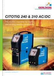
<strong>CITOLINE</strong>: friendly and easy to adjust.<br />
<strong>CITOLINE</strong> 1700 M<br />
<strong>CITOLINE</strong> M/T<br />
<strong>CITOLINE</strong> (S)<br />
2007-180<br />
4<br />
6<br />
1<br />
3<br />
I<br />
5<br />
A<br />
2<br />
K<br />
J<br />
I<br />
A<br />
7<br />
K<br />
3<br />
2007-126<br />
J<br />
2007-177<br />
1<br />
2<br />
3<br />
4<br />
5<br />
6<br />
7<br />
A<br />
B<br />
3<br />
C<br />
D<br />
E<br />
Trans<strong>for</strong>mer temperature monitoring indicator light<br />
Step time potentiometer<br />
(if used <strong>for</strong> continuous <strong>welding</strong>, potentiometer in “timer off” position)<br />
Torch connector, “Euro” type<br />
Voltage switch<br />
(used to adjust <strong>the</strong> voltage)<br />
Wire speed regulation potentiometer<br />
(carries out current calibration)<br />
Primary power supply cable<br />
Ground cable with its clamp<br />
Digital Volt/Ampere display<br />
•Shows <strong>the</strong> parameters be<strong>for</strong>e<br />
and after <strong>welding</strong>.<br />
•Facilitates parameter setting.<br />
Welding cycle selector<br />
•2T: pressing <strong>the</strong> trigger<br />
activates <strong>the</strong> arc, releasing<br />
it activates <strong>the</strong> end of <strong>the</strong> cycle.<br />
•4T: pressing <strong>the</strong> trigger starts <strong>the</strong><br />
cycle, <strong>the</strong> trigger can be<br />
released. Pressing it again stops<br />
<strong>the</strong> cycle.<br />
•Spot weld: supplies a <strong>welding</strong><br />
current <strong>for</strong> a given time.<br />
Torch connector<br />
Step time<br />
•Used to set <strong>the</strong> spot <strong>welding</strong><br />
time.<br />
Priming speed<br />
•Sets <strong>the</strong> wire run-up speed<br />
which improves arc striking.<br />
Anti-sticking<br />
•Adjusts <strong>the</strong> length of <strong>the</strong> “burnt”<br />
wire at <strong>the</strong> end of <strong>welding</strong>. This<br />
function avoids <strong>the</strong> wire sticking<br />
to <strong>the</strong> workpiece.<br />
WIRE FEEDER DV 4004 CTL<br />
2007-180<br />
A<br />
3<br />
B<br />
C<br />
D<br />
E<br />
F<br />
G<br />
H<br />
I<br />
J<br />
K<br />
Wire speed potentiometer<br />
•Allow continuous adjustment<br />
of <strong>the</strong> wire feed speed.<br />
Wire test<br />
•Checks <strong>the</strong> wire feed<br />
mechanism is working properly.<br />
Test gas<br />
•Used to check <strong>the</strong> gasflow.<br />
Switch<br />
•Switch on and pre-adjustment<br />
of <strong>the</strong> <strong>welding</strong> voltage.<br />
Voltage selector switch<br />
•Allows <strong>the</strong> voltage to <strong>the</strong><br />
terminals of <strong>the</strong> <strong>welding</strong> circuit<br />
to be finely adjusted.<br />
Grounding cable terminals:<br />
•On small inductance coil:<br />
dynamic and penetrating arc<br />
•On large inductance coil:<br />
soft arc, damp cable.<br />
G H<br />
F<br />
8
<strong>CITOLINE</strong>: wear parts-options<br />
Wire feeder parts Ø 0.6 mm Ø 0.8 mm Ø 1.0 mm Ø 1.2 mm Ø 1.4 mm Ø 1.6 mm<br />
Specific to <strong>CITOLINE</strong> 1700 M<br />
Rollers <strong>for</strong> steel and stainless steel wires<br />
O<strong>the</strong>r models of <strong>CITOLINE</strong><br />
W 000 232 110 W 000 232 112 - - -<br />
Entry wire guide W 000 233 472<br />
Rollers <strong>for</strong> steel and stainless steel wires W 000 050 096 W 000 050 097 W 000 050 098 W 000 050 099 - W 000 218 767<br />
Rollers <strong>for</strong> flux cored wires - - W 000 264 870 W 000 265 883<br />
Rollers <strong>for</strong> aluminium wires - W 000 050 100 W 000 050 101 W 000 050 102 - -<br />
WELDLINE torches<br />
Torche name Duty cycle at 60 %<br />
Air cooled torches<br />
Cat. no. Max wire Ø<br />
WMT 15 A<br />
3 m<br />
4 m<br />
180 A<br />
W 000 010 600<br />
W 000 010 601<br />
1.0 mm<br />
3 m<br />
W 000 010 602<br />
WMT 25 A 4 m 230 A<br />
W 000 010 603<br />
1.2 mm<br />
5 m W 000 010 604<br />
3 m<br />
W 000 010 605<br />
WMT 36 A 4 m 340 A<br />
W 000 010 606<br />
1.6 mm<br />
5 m W 000 010 607<br />
Water cooled torches<br />
3 m<br />
W 000 010 608<br />
WMT 500 W 4 m 500 A<br />
W 000 010 609<br />
1.6 mm<br />
5 m W 000 010 610<br />
Torch arm rest<br />
2 models in <strong>the</strong> range<br />
1 <strong>for</strong> <strong>CITOLINE</strong> compact version:<br />
W 000 261 845<br />
2 <strong>for</strong> <strong>CITOLINE</strong> separate version:<br />
W 000 261 846<br />
Arm adjustable up to 2.5 meters length.<br />
2005-937<br />
1<br />
2<br />
2005-936<br />
CHAMELEON F, CHAMELEON 3V &<br />
CHAMELEON 3V+ self darkening helmets.<br />
CHAMELEON F and 3V helmets are self darkening masks equipped<br />
with a fixed liquid crystal cell <strong>for</strong> <strong>the</strong> F type (DIN 3/11),<br />
and a variable one <strong>for</strong> <strong>the</strong> 3V type (DIN 4/9-13). Very light,<br />
this high technology helmets are sold with an adjustable headgear.<br />
CHAMELEON 3F<br />
Type fixed cell<br />
DIN 3/11<br />
CHAMELEON 3V<br />
Type variable cell<br />
DIN 4/9-13<br />
specially designed<br />
<strong>for</strong> MMA, MIG/MAG<br />
CHAMELEON 3V+<br />
Type variable cell<br />
DIN 4/9-13<br />
covering all processes<br />
especially TIG<br />
2004-616<br />
2004-619<br />
2004-620<br />
2004-625<br />
2006-218<br />
W 000 261 351<br />
W 000 261 352<br />
W 000 261 353<br />
9<br />
2570-028
Contacts in Europe<br />
BELGIUM<br />
AIR LIQUIDE WELDING BELGIUM SA<br />
Z.I. West Grijpen - Grijpenlaan 5 - 3300 TIENEN<br />
Tel.: +32 16 80 48 20 - Fax: +32 16 78 29 22<br />
CZECH REPUBLIC<br />
AIR LIQUIDE CZ S.R.O. - Welding & Cutting<br />
Jinonickà 80 - 15800 PRAHA 5<br />
Tel.: +420 257 290 384 - Fax: +420 257 290 428<br />
FRANCE<br />
AIR LIQUIDE WELDING FRANCE<br />
13, rue d’Épluches - BP 70024 Saint-Ouen l'Aumône<br />
95315 CERGY PONTOISE Cedex<br />
Tel. : +33 1 34 21 33 33 - Fax : +33 1 34 21 31 30<br />
GERMANY<br />
OERLIKON SCHWEISSTECHNIK GmbH<br />
Industriestrasse 12 - D-67304 EISENBERG/PFALZ<br />
Tel.: +49 6351 4760 - Fax: +49 6351 476 335<br />
HUNGARY<br />
AIR LIQUIDE HUNGARY - Welding & Cutting<br />
IPARI GAZTERMELÖ KFT.<br />
Pannonia Center-Pannonia u.11. - H-1136 BUDAPEST XIII,<br />
Tel./Fax: +36 1 239 4060<br />
ITALY<br />
AIR LIQUIDE WELDING ITALY<br />
Via Torricelli 15/A - 37135 VERONA<br />
Tel.: +39 045 82 91 511 - Fax: +39 045 82 91 536<br />
NETHERLANDS<br />
AIR LIQUIDE WELDING NETHERLANDS<br />
Rudonk 6 B - NL 4824 AJ BREDA<br />
Tel.: +31 76 541 00 80 - Fax: +31 76 541 58 96<br />
POLAND<br />
AIR LIQUIDE WELDING POLSKA - SP. Z.o.o<br />
UL. Porcelanowa 10 - 40-246 KATOWICE<br />
Tel.: +48 32 609 04 50 - Fax: +48 32 609 04 60<br />
PORTUGAL<br />
AIR LIQUIDE SOLDADURA LDA<br />
Rua Dr. António Loureiro Borges, 4-2° Arquiparque<br />
Miraflores - 1495-131 ALGÉS<br />
Tel: +351 21 41 64 900 - Fax: +351 21 41 69 40<br />
ALW<br />
International Development Department<br />
Italy<br />
FRO - AIR LIQUIDE WELDING ITALIE<br />
Via Torricelli15/A<br />
37135 VERONA<br />
Tel: +39 045 82 91 511<br />
Fax: +39 045 82 91 536<br />
Email: export.alwitaly@airliquide.com<br />
www.airliquide.com<br />
ROMANIA<br />
DUCTIL<br />
Aleea Industriilor Nr 1 - 120224 BUZAU<br />
Tel.: +40 238 722 058 - Fax: +40 238 716 861<br />
RUSSIA<br />
AIR LIQUIDE WELDING<br />
Ул. �opoнцовская д. 17 - MО���А 109147<br />
Tел.: +7 (495) 641 28 98 - �aкс: +7 (495) 641 28 91<br />
E-mail: vladimir.lebedev@airliquide.com<br />
SCANDINAVIA<br />
OERLIKON SKANDINAVIEN AB<br />
Krossverksgatan 7 - 216 16 LIMHAMN<br />
Tel. : +46 (0)40 670 15 00 - Fax : +46 (0)40 670 15 01<br />
SLOVAKIA<br />
AIR LIQUIDE WELDING CENTRAL EUROPE S.R.O.<br />
Prazska 35 - 94901 NITRA<br />
Tel.: +421 37 65 19 919 - Fax: +421 37 65 19 919<br />
SPAIN<br />
OERLIKON SOLDADURA SA<br />
Poligono Industrial la Noria Carretera de Castellon<br />
Km-15,500 - 50730 El Burgo de Ebro - ZARAGOZA<br />
Tel.: +34 976 10 47 00 - Fax: +34 976 10 42 67<br />
SWITZERLAND<br />
OERLIKON - SCHWEISSTECHNIK-AG<br />
Neunbrunnenstrasse 50 - CH 8050 ZÜRICH<br />
Tel.: +41 44 307 61 11 - Fax: +41 44 307 65 30<br />
UAE<br />
AIR LIQUIDE WELDING MIDDLE EAST FZE<br />
Jebel Ali free zone warehouse No. FZS1AH05<br />
P.O. BOX 18734 - Jebel Ali - DUBAI<br />
Tel.: +971(0)48861606 - Fax: +971(0)48861608<br />
U. K.<br />
AIR LIQUIDE WELDING Ltd<br />
Low March / London Road - DAVENTRY<br />
Northants NN11 4SD<br />
Tel.: +44 1 327 70 55 11 - Fax: +44 1 327 70 13 10<br />
Contacts <strong>for</strong> o<strong>the</strong>r coutries<br />
ALW<br />
International Development Department<br />
France<br />
13, rue d'Epluches<br />
BP 70024 Saint Ouen l'Aumône<br />
95315 CERGY-PONTOISE Cedex<br />
Tel: +33 1 34 21 33 33<br />
Fax: +33 1 30 37 19 73<br />
Email: export.alwfrance@airliquide.com<br />
www.oerlikon-<strong>welding</strong>.com<br />
ALW<br />
International Development Department<br />
Switzerland<br />
OERLIKON - SCHWEISSTECHNIK-AG<br />
Mandachstrasse 54<br />
CH 8155 NIEDERHASLI<br />
Tel: + 41 44 307 61 11<br />
Fax: + 41 44 307 61 12<br />
Email: export.oerlikon<strong>welding</strong>@airliquide.com<br />
Air Liquide is <strong>the</strong> world leader in gases <strong>for</strong> industry, health and <strong>the</strong> environment, and is present in over 75 countries with 43,000 employees. Oxygen, nitrogen, hydrogen<br />
and rare gases have been at <strong>the</strong> core of Air Liquide’s activities since its creation in 1902. Using <strong>the</strong>se molecules, Air Liquide continuously reinvents its business, anticipating<br />
<strong>the</strong> needs of current and future markets. The Group innovates to enable progress, to achieve dynamic growth and a consistent per<strong>for</strong>mance.<br />
Air Liquide combines many products and technologies to develop valuable applications and services not only <strong>for</strong> its customers but also <strong>for</strong> society.<br />
Air Liquide Welding France reserves <strong>the</strong> right to carry out modifications to its machinery without prior notice.<br />
The manufacturer accepts no liability <strong>for</strong> illustrations, descriptions and characteristics, which are <strong>for</strong> in<strong>for</strong>mation only.<br />
© ALWF W 000 267 722<br />
07 2009 - S 05 Ed. 2<br />
QB : 2501 - Photos : ALWF