STT173 - Honeywell
STT173 - Honeywell
STT173 - Honeywell
Create successful ePaper yourself
Turn your PDF publications into a flip-book with our unique Google optimized e-Paper software.
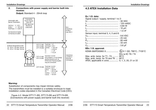
Installation Drawings2. Connections with power supply and barrier built intoreceiver.Output: Standard 4 - 20mA loopIntrinsically safeBarrier Parameters.Uo(Voc) =< 30 VIo(Isc) =< 120 mAPo(Pmax) =< 0.84 WCa>Sum(Ci)+CcableLa>Sum(Li)+LcableAmbient temperature limitsT4: -40 to + 85 deg. CelciusT6: -40 to + 60 deg. CelciusTransmitterPower Supplybuilt intoCSA approvedReceivingInstrument1 26+ -5SENSOR43STT171-BS<strong>STT173</strong>-BSSTT17H-BSSTT171-BS<strong>STT173</strong>-BSSTT17H-BSTerminal: 1-2Ui(Vmax) = 30 VIi(Imax) = 120 mAPi = 0.84 WCi = 1 nFLi = 10 uHTerminal: 3,4,5,6Only passive, or non-energystoring devices such asRTD's and Thermocouplesmay be connected.Terminal: 3,4,5,6Uo(Voc) = 9.6 VIo(Isc) = 28 mAPo = 67.2 mWCo(Ca) = 3.5 uFLo(La) = 35 mHNonhazardouslocationmax 250 VHazardousLocations /SécuritéIntrinséque4.3 ATEX Installation DataEx / I.S. data:Signal output / supply, terminal 1 to 2:U i .................................................... : 30 VDCI i ...................................................... : 120 mADCP i ..................................................... : 0.84 WL i ..................................................... : 10 µHC i .................................................... : 1.0 nFSensor input, terminal 3, 4, 5 and 6:U o .................................................... : 9.6 VDCI o ..................................................... : 25 mAP o .................................................... : 60 mWL o .................................................... : 33 mHC o .................................................... : 3.6 µFEEx / I.S. approval:KEMA 06ATEX0063 X .....................Installation DrawingsII 1 GD, T80°C...T105°CEEx ia IIC T6 / T4Max. amb. temp. for T1...T4 .......... 85°CMax. amb. temp. for T5 and T6 .... 60°CATEX, applicable in zone ................ 0, 1, 2, 20, 21 or 22Warning:Substitution of components may impair intrinsic safety.The transmitters must be installed in a suitable enclosure to meetinstallation codes stipulated in the Canadian Electrical Code (CEC).Figure 4-3 Model STT171-BS, <strong>STT173</strong>-BS and STT17H-BS[Connections with power supply and barrier built into receiver]22 <strong>STT173</strong> Smart Temperature Transmitter Operator Manual 2/062/06 <strong>STT173</strong> Smart Temperature Transmitter Operator Manual 23


