servo and sensor control on small mobile platforms - Engineering ...
servo and sensor control on small mobile platforms - Engineering ...
servo and sensor control on small mobile platforms - Engineering ...

You also want an ePaper? Increase the reach of your titles
YUMPU automatically turns print PDFs into web optimized ePapers that Google loves.
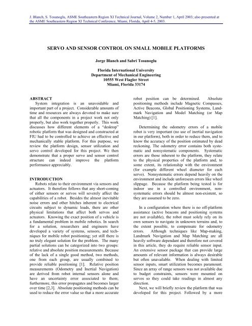
J. Blanch, S. Tosunoglu, ASME Southeastern Regi<strong>on</strong> XI Technical Journal, Volume 2, Number 1, April 2003; also presented atthe ASME Southeastern Regi<strong>on</strong> XI Technical C<strong>on</strong>ference, Miami, Florida, April 4-5, 2003.SERVO AND SENSOR CONTROL ON SMALL MOBILE PLATFORMSJorge Blanch <str<strong>on</strong>g>and</str<strong>on</strong>g> Sabri TosunogluFlorida Internati<strong>on</strong>al UniversityDepartment of Mechanical <strong>Engineering</strong>10555 West Flagler StreetMiami, Florida 33174ABSTRACTSystem integrati<strong>on</strong> is an unavoidable <str<strong>on</strong>g>and</str<strong>on</strong>g>important part of a project. C<strong>on</strong>siderable amounts oftime <str<strong>on</strong>g>and</str<strong>on</strong>g> resources are always devoted to make surethat all the comp<strong>on</strong>ents in a project work not <strong>on</strong>lyproperly, but also work together properly. This workdiscusses how different elements of a “desktop”robotic platform that was designed <str<strong>on</strong>g>and</str<strong>on</strong>g> c<strong>on</strong>structed atFIU had to be <str<strong>on</strong>g>c<strong>on</strong>trol</str<strong>on</strong>g>led to achieve an effective <str<strong>on</strong>g>and</str<strong>on</strong>g>mechanically stable platform. For this purpose, wereview the platform design, <str<strong>on</strong>g>sensor</str<strong>on</strong>g> utilizati<strong>on</strong> <str<strong>on</strong>g>and</str<strong>on</strong>g><str<strong>on</strong>g>servo</str<strong>on</strong>g> <str<strong>on</strong>g>c<strong>on</strong>trol</str<strong>on</strong>g> developed for this project. We thendem<strong>on</strong>strate that a proper <str<strong>on</strong>g>servo</str<strong>on</strong>g> <str<strong>on</strong>g>and</str<strong>on</strong>g> <str<strong>on</strong>g>sensor</str<strong>on</strong>g> <str<strong>on</strong>g>c<strong>on</strong>trol</str<strong>on</strong>g>structure can indeed improve the platformperformance appreciably.INTRODUCTIONRobots relate to their envir<strong>on</strong>ment via <str<strong>on</strong>g>sensor</str<strong>on</strong>g>s <str<strong>on</strong>g>and</str<strong>on</strong>g>actuators. It therefore follows that any short-comingof either <str<strong>on</strong>g>sensor</str<strong>on</strong>g>s or <str<strong>on</strong>g>servo</str<strong>on</strong>g>s will severely affect thecapabilities of a robot. Besides the almost inevitablenoise errors <str<strong>on</strong>g>and</str<strong>on</strong>g> other hitches inherent to electricalcircuits subject to dynamic loads, there are otherphysical limitati<strong>on</strong>s that affect both <str<strong>on</strong>g>servo</str<strong>on</strong>g>s <str<strong>on</strong>g>and</str<strong>on</strong>g>actuators. Knowing the exact positi<strong>on</strong> of a vehicle isa fundamental problem in <strong>mobile</strong> robotics. In searchfor a soluti<strong>on</strong>, researchers <str<strong>on</strong>g>and</str<strong>on</strong>g> engineers havedeveloped a variety of systems, <str<strong>on</strong>g>sensor</str<strong>on</strong>g>s, <str<strong>on</strong>g>and</str<strong>on</strong>g> techniquesfor <strong>mobile</strong> robot positi<strong>on</strong>ing; yet still there isno truly elegant soluti<strong>on</strong> for the problem. The manypartial soluti<strong>on</strong>s can be categorized into two groups:relative <str<strong>on</strong>g>and</str<strong>on</strong>g> absolute positi<strong>on</strong> measurements. Becauseof the lack of a single good method, two methods,<strong>on</strong>e from each group, are usually combined toprovide reliable positi<strong>on</strong>ing [1]. Relative positi<strong>on</strong>measurements (Odometry <str<strong>on</strong>g>and</str<strong>on</strong>g> Inertial Navigati<strong>on</strong>)are derived from robot internal <str<strong>on</strong>g>sensor</str<strong>on</strong>g>s al<strong>on</strong>e <str<strong>on</strong>g>and</str<strong>on</strong>g>have an uncertainty error associated to them;furthermore, this error propagates <str<strong>on</strong>g>and</str<strong>on</strong>g> becomes largerover time [2,3]. Absolute positi<strong>on</strong>ing methods can beused to reduce the error value so that a more accuraterobot positi<strong>on</strong> can be determined. Absolutepositi<strong>on</strong>ing methods include Magnetic Compasses,Active Beac<strong>on</strong>s, Global Positi<strong>on</strong>ing Systems, L<str<strong>on</strong>g>and</str<strong>on</strong>g>markNavigati<strong>on</strong> <str<strong>on</strong>g>and</str<strong>on</strong>g> Model Matching (or MapMatching) [1].Determining the odometry errors of a <strong>mobile</strong>robot is very important (no use of inertial navigati<strong>on</strong>in our platform), both in order to reduce them, <str<strong>on</strong>g>and</str<strong>on</strong>g> toknow the accuracy of the positi<strong>on</strong> estimated by deadreck<strong>on</strong>ing. The odometry error c<strong>on</strong>tains both systematic<str<strong>on</strong>g>and</str<strong>on</strong>g> n<strong>on</strong>systematic comp<strong>on</strong>ents. Systematicerrors are those inherent to the platform, they relateto the physical properties of the platform <str<strong>on</strong>g>and</str<strong>on</strong>g>, tosome extent, its relati<strong>on</strong>ship with the envir<strong>on</strong>ment(for example different wheel diameter for each<str<strong>on</strong>g>servo</str<strong>on</strong>g>). N<strong>on</strong>systematic errors depend heavily <strong>on</strong> theenvir<strong>on</strong>ment <str<strong>on</strong>g>and</str<strong>on</strong>g> include unforeseen errors like wheelslippage. Because the platform being tested is forindoor use in a <str<strong>on</strong>g>c<strong>on</strong>trol</str<strong>on</strong>g>led envir<strong>on</strong>ment, n<strong>on</strong>systematicerrors should be almost n<strong>on</strong>-existent, sothey are assumed to be zero.In a c<strong>on</strong>figurati<strong>on</strong> where there is no off-platformassistance (active beac<strong>on</strong>s <str<strong>on</strong>g>and</str<strong>on</strong>g> positi<strong>on</strong>ing systemsare not available), the robot must solely rely <strong>on</strong> itsown <str<strong>on</strong>g>sensor</str<strong>on</strong>g>s to navigate in unknown terrains <str<strong>on</strong>g>and</str<strong>on</strong>g>, tothe extent possible, to compensate for odometryerrors. Although techniques like Map-making,L<str<strong>on</strong>g>and</str<strong>on</strong>g>mark Navigati<strong>on</strong> <str<strong>on</strong>g>and</str<strong>on</strong>g> Map Matching are allheavily software dependant <str<strong>on</strong>g>and</str<strong>on</strong>g> therefore not coveredin this article, they do require reliable <str<strong>on</strong>g>sensor</str<strong>on</strong>g> input.An extensive <str<strong>on</strong>g>sensor</str<strong>on</strong>g> package that can provide largeamounts of relevant informati<strong>on</strong> is always desirablebut often unavailable. When dealing with limited<str<strong>on</strong>g>sensor</str<strong>on</strong>g> inputs, smart utilizati<strong>on</strong> becomes paramount.Since an array of range <str<strong>on</strong>g>sensor</str<strong>on</strong>g>s was not available dueto budget c<strong>on</strong>straints, <str<strong>on</strong>g>sensor</str<strong>on</strong>g>s were mounted <strong>on</strong><str<strong>on</strong>g>servo</str<strong>on</strong>g>s so they could take readings in almost anydirecti<strong>on</strong>.Next, we will briefly review the platform that wasdeveloped for this project. Followed by a more
J. Blanch, S. Tosunoglu, ASME Southeastern Regi<strong>on</strong> XI Technical Journal, Volume 2, Number 1, April 2003; also presented atthe ASME Southeastern Regi<strong>on</strong> XI Technical C<strong>on</strong>ference, Miami, Florida, April 4-5, 2003.detailed review of the main comp<strong>on</strong>ents such as the<str<strong>on</strong>g>servo</str<strong>on</strong>g>s <str<strong>on</strong>g>and</str<strong>on</strong>g> <str<strong>on</strong>g>sensor</str<strong>on</strong>g>s <str<strong>on</strong>g>and</str<strong>on</strong>g> how they are <str<strong>on</strong>g>c<strong>on</strong>trol</str<strong>on</strong>g>led tomake this an effective <str<strong>on</strong>g>and</str<strong>on</strong>g> mechanically stableplatform. Finally, some c<strong>on</strong>clusi<strong>on</strong>s will be drawn asto the quality <str<strong>on</strong>g>and</str<strong>on</strong>g> precisi<strong>on</strong> of a platform built withoff the shelf comp<strong>on</strong>ents meant for hobbyists.PLATFORMThe platform used in this case is HANCOR(H<str<strong>on</strong>g>and</str<strong>on</strong>g>held-C<strong>on</strong>trolled Rover), a <strong>small</strong> rover createdat Florida Internati<strong>on</strong>al University to test the viabilityof using h<str<strong>on</strong>g>and</str<strong>on</strong>g>held devices as platform <str<strong>on</strong>g>c<strong>on</strong>trol</str<strong>on</strong>g>lers.The platform is based <strong>on</strong> a P<strong>on</strong>tech SV203 <str<strong>on</strong>g>servo</str<strong>on</strong>g><str<strong>on</strong>g>c<strong>on</strong>trol</str<strong>on</strong>g>ler board that uses Sharp GP2D120 infraredranger <str<strong>on</strong>g>sensor</str<strong>on</strong>g>s to detect obstacles <str<strong>on</strong>g>and</str<strong>on</strong>g> Futaba-type<str<strong>on</strong>g>servo</str<strong>on</strong>g>motors (<str<strong>on</strong>g>servo</str<strong>on</strong>g>s used in radio-<str<strong>on</strong>g>c<strong>on</strong>trol</str<strong>on</strong>g>led modelairplanes, cars, etc.) to drive the wheels. An <strong>on</strong>boardPalm III h<str<strong>on</strong>g>and</str<strong>on</strong>g>held <str<strong>on</strong>g>c<strong>on</strong>trol</str<strong>on</strong>g>s the platform [4,5,6].SERVOSSmall budget <strong>platforms</strong> like the HANCOR oftenreplace expensive <str<strong>on</strong>g>servo</str<strong>on</strong>g>s <str<strong>on</strong>g>and</str<strong>on</strong>g> positi<strong>on</strong> encoders withoff-the shelf radio <str<strong>on</strong>g>c<strong>on</strong>trol</str<strong>on</strong>g>led <str<strong>on</strong>g>servo</str<strong>on</strong>g>motors. RC<str<strong>on</strong>g>servo</str<strong>on</strong>g>s are cheap, easy to <str<strong>on</strong>g>c<strong>on</strong>trol</str<strong>on</strong>g>, come in a c<strong>on</strong>venientform factor <str<strong>on</strong>g>and</str<strong>on</strong>g> are available in different sizes,speeds <str<strong>on</strong>g>and</str<strong>on</strong>g> power ratings. Servomotors are generallyemployed for positi<strong>on</strong> <str<strong>on</strong>g>c<strong>on</strong>trol</str<strong>on</strong>g>; they use a potentiometeras feedback to determine their positi<strong>on</strong>. The<str<strong>on</strong>g>servo</str<strong>on</strong>g> compares its current positi<strong>on</strong> to an input PWMsignal, <str<strong>on</strong>g>and</str<strong>on</strong>g> then moves until its positi<strong>on</strong> matches theinput signal. The “width” of the signal pulse may lastanywhere from 0.6 millisec<strong>on</strong>ds (minimum positi<strong>on</strong>),to 2.4 ms (maximum positi<strong>on</strong>). The Pulse is repeatedevery 14 to 20 millisec<strong>on</strong>ds (figure 2) [9]. Regular<str<strong>on</strong>g>servo</str<strong>on</strong>g>motors are used for the positi<strong>on</strong>ing of the range<str<strong>on</strong>g>sensor</str<strong>on</strong>g>s, but <str<strong>on</strong>g>c<strong>on</strong>trol</str<strong>on</strong>g>ling the driving <str<strong>on</strong>g>servo</str<strong>on</strong>g>s requiresome modificati<strong>on</strong>s.Figure 2. Futaba-type <str<strong>on</strong>g>servo</str<strong>on</strong>g> timing diagram.Figure 1. HANCOR platform (h<str<strong>on</strong>g>and</str<strong>on</strong>g>heldc<strong>on</strong>nected but not mounted).The <str<strong>on</strong>g>servo</str<strong>on</strong>g> <str<strong>on</strong>g>c<strong>on</strong>trol</str<strong>on</strong>g>ler board is based <strong>on</strong> aPIC16C73 microchip; it accepts serial data from ahost computer (replaced by the Palm III h<str<strong>on</strong>g>and</str<strong>on</strong>g>held inthis case) <str<strong>on</strong>g>and</str<strong>on</strong>g> outputs a PWM (Pulse WidthModulated) signal to <str<strong>on</strong>g>c<strong>on</strong>trol</str<strong>on</strong>g> up to eight RC <str<strong>on</strong>g>servo</str<strong>on</strong>g>motors[10]. Two <str<strong>on</strong>g>servo</str<strong>on</strong>g>s, modified for c<strong>on</strong>tinuousrotati<strong>on</strong>, provide power for the driving wheels.Besides <str<strong>on</strong>g>servo</str<strong>on</strong>g>s, the board can <str<strong>on</strong>g>c<strong>on</strong>trol</str<strong>on</strong>g> other digitaldevices that require an <strong>on</strong>/off signal to be activated.Up to 5 <str<strong>on</strong>g>sensor</str<strong>on</strong>g>s can be c<strong>on</strong>nected to the A/D inputheader, which reads analog voltages between 0 <str<strong>on</strong>g>and</str<strong>on</strong>g> 5Volts. The <str<strong>on</strong>g>sensor</str<strong>on</strong>g> package c<strong>on</strong>sists of two infraredrange <str<strong>on</strong>g>sensor</str<strong>on</strong>g>s <str<strong>on</strong>g>and</str<strong>on</strong>g> <strong>on</strong>e digital compass. The digitalcompass has a resoluti<strong>on</strong> of +/- 22 o (it detects N, NE,E, SE, etc.), so it cannot be used as a reliable <str<strong>on</strong>g>sensor</str<strong>on</strong>g>input, but can later be used as aid during mapmatching [7]. The IR <str<strong>on</strong>g>sensor</str<strong>on</strong>g>s are mounted <strong>on</strong> two<strong>small</strong> <str<strong>on</strong>g>servo</str<strong>on</strong>g>s so that they can pan to any directi<strong>on</strong> in a135 o forward-looking field of viewFutaba-type Servomotors were not developed forc<strong>on</strong>tinuous rotati<strong>on</strong>. In order to utilize <str<strong>on</strong>g>servo</str<strong>on</strong>g>s insituati<strong>on</strong>s that require c<strong>on</strong>tinuous rotati<strong>on</strong> they haveto be modified. Servos were not designed forvelocity <str<strong>on</strong>g>c<strong>on</strong>trol</str<strong>on</strong>g> either. The velocity of a <str<strong>on</strong>g>servo</str<strong>on</strong>g>depends <strong>on</strong> how far it is from the desired positi<strong>on</strong>.The <str<strong>on</strong>g>servo</str<strong>on</strong>g> will spin at top speed until it gets close tothe desired value, then it will quickly slow down toavoid over-shooting the target positi<strong>on</strong>. Usually,c<strong>on</strong>tinuous rotati<strong>on</strong> <str<strong>on</strong>g>and</str<strong>on</strong>g> velocity <str<strong>on</strong>g>c<strong>on</strong>trol</str<strong>on</strong>g> go h<str<strong>on</strong>g>and</str<strong>on</strong>g> inh<str<strong>on</strong>g>and</str<strong>on</strong>g>. Servos that have been “hacked” for c<strong>on</strong>tinuousrotati<strong>on</strong> have the feedback potentiometer de-coupledfrom the output gear <str<strong>on</strong>g>and</str<strong>on</strong>g> set to a c<strong>on</strong>stant value (forexample 90 o ). The velocity is <str<strong>on</strong>g>c<strong>on</strong>trol</str<strong>on</strong>g>led by givingthe <str<strong>on</strong>g>servo</str<strong>on</strong>g> a target positi<strong>on</strong> (0 to 180 o ), but since thefeedback has been fixed at 90 o , the <str<strong>on</strong>g>servo</str<strong>on</strong>g> will spinforever towards the target positi<strong>on</strong>. The further thetarget positi<strong>on</strong> from the fixed positi<strong>on</strong> (90 o ), thefaster the <str<strong>on</strong>g>servo</str<strong>on</strong>g> will spin.The P<strong>on</strong>tech SV203 <str<strong>on</strong>g>c<strong>on</strong>trol</str<strong>on</strong>g>s its <str<strong>on</strong>g>servo</str<strong>on</strong>g>s via an 8-bit signal (PWM). An 8-bit signal can take 2 8 values(from 0 to 255). If we define the 0 signal as 0 o <str<strong>on</strong>g>and</str<strong>on</strong>g>
J. Blanch, S. Tosunoglu, ASME Southeastern Regi<strong>on</strong> XI Technical Journal, Volume 2, Number 1, April 2003; also presented atthe ASME Southeastern Regi<strong>on</strong> XI Technical C<strong>on</strong>ference, Miami, Florida, April 4-5, 2003.the 255 signal as 180 o , then the 90 o signal will be128. As can be seen from the data in figure 3, the<str<strong>on</strong>g>servo</str<strong>on</strong>g> quickly reaches top speed, which leaves us witha relatively <strong>small</strong> range of useful bit values (roughlyfrom 90 to 170 in our case). Values outside thisrange will not result in a significant speed variati<strong>on</strong>.revoluti<strong>on</strong>s per sec<strong>on</strong>dServo speedRange of interest10.80.60.40.20-0.2-0.4-0.6-0.8-10 100 200Bit valueleftrightFigure 3. Servo speed measurements.Servo speeds were measured (in revoluti<strong>on</strong>s persec<strong>on</strong>d) at different bit signals <str<strong>on</strong>g>and</str<strong>on</strong>g> stored in Excel(figure 3). Data was then transferred to Matlab toperform some numerical analyses <strong>on</strong> it; the objectivebeing to find an equati<strong>on</strong> that will return the bit valueneeded to achieve a desired rotati<strong>on</strong>al velocity.To effectively approximate the data, it first hat tobe transformed <str<strong>on</strong>g>and</str<strong>on</strong>g> formatted. Two processes wererequired. First, the order of the data pairs waschanged so that velocity would be our independentvariable (input) <str<strong>on</strong>g>and</str<strong>on</strong>g> the calculated bit our dependentvariable (output). Sec<strong>on</strong>dly, <strong>on</strong>ly values in the rangeof interest were used; this helped to generate atighter-fitting curve, since <strong>on</strong>ly relevant data wasbeing used (figure 4).The 3 rd degree polynomial approximati<strong>on</strong> [13]that fit the data (from about –0.9 to 0.9) as given byMatlab was:Right bit(v) =31.224v 3 + 0.451v 2 + 15.72v + 128.948Left bit(v) = -33.272v 3 + 1.504v 2 -15.294v + 130.273The 3 rd degree approximati<strong>on</strong> looked promisingbut when tested <strong>on</strong> the platform it did not perform aswell as expected; the platform could not describe astraight path. This approximati<strong>on</strong> is not a methodthat is accurate enough to drive the platform.Bit ValueRPSFigure 4. Actual values <str<strong>on</strong>g>and</str<strong>on</strong>g> 3 rd degree polynomialapproximati<strong>on</strong>s.Another curve-fitting method that can betterapproximate the data is the use of splines [13].Splines are polynomial approximati<strong>on</strong>s that are usedto fit sub-regi<strong>on</strong>s of the data. Since the secti<strong>on</strong> of thecurve to be approximated is <strong>small</strong>er, a much higherdegree of accuracy can be achieved.Data points were then chosen subjectively tobreak up the curves in secti<strong>on</strong>s that presented similarbehavior (curvature) (table 1). A simple linearapproximati<strong>on</strong> from <strong>on</strong>e point to the next (splines of1 st degree) provided a much better fit to the originaldata (figure 5) than the 3 rd degree polynomialscalculated previously. Of course, this came at thecost of having 9 linear equati<strong>on</strong>s for each 3 rd degreepolynomial.Bit ValueLeft <str<strong>on</strong>g>and</str<strong>on</strong>g> Right wheel velocitiesLeft <str<strong>on</strong>g>and</str<strong>on</strong>g> Right wheel velocitiesRPSFigure 5. Close-up of range of interest: Gathereddata with extracted points superimposed.
J. Blanch, S. Tosunoglu, ASME Southeastern Regi<strong>on</strong> XI Technical Journal, Volume 2, Number 1, April 2003; also presented atthe ASME Southeastern Regi<strong>on</strong> XI Technical C<strong>on</strong>ference, Miami, Florida, April 4-5, 2003.Table 1. Data extracted from range of interest.Left Rightbit rps rps90 0.880282 -0.8787394 0.857633 -0.85106104 0.802568 -0.78125112 0.673401 -0.64516120 0.423729 -0.36058140 -0.4 0.454545146 -0.59032 0.648508152 -0.72464 0.761035164 -0.82781 0.859107168 -0.8489 0.874126Two observati<strong>on</strong>s that persuade against searchingfor more accurate approximati<strong>on</strong>s are: 1, theexperimental measurements are subject to error;depending <strong>on</strong> the accuracy of the reading or even <strong>on</strong>the battery charge, values will vary slightly from <strong>on</strong>erun to the next. And 2, bit comm<str<strong>on</strong>g>and</str<strong>on</strong>g>s are integers;therefore there will be gaps in the velocity curves forvalues that could never be reached because theycorresp<strong>on</strong>d to a bit value between two integers. Onthe other h<str<strong>on</strong>g>and</str<strong>on</strong>g>, the closeness of the splineapproximati<strong>on</strong> to the actual data showed thatselecting a few finite points can offer sufficient<str<strong>on</strong>g>c<strong>on</strong>trol</str<strong>on</strong>g> over the velocity. Not using an equati<strong>on</strong> (orseveral) to find the bit value corresp<strong>on</strong>ding to adesired velocity, results in a crude <str<strong>on</strong>g>c<strong>on</strong>trol</str<strong>on</strong>g> over speedvalues; but, by finding the bit values that corresp<strong>on</strong>dto specific velocities (0.8, 0.6, 0.4, 0.2, 0.0, -0.2, -0.4,-0.6 <str<strong>on</strong>g>and</str<strong>on</strong>g> –0.8 rps, per se), the velocity of the platformcan be properly <str<strong>on</strong>g>c<strong>on</strong>trol</str<strong>on</strong>g>led for its full range of values.Figure 6. Distance <str<strong>on</strong>g>and</str<strong>on</strong>g> angle calculati<strong>on</strong>.SENSORSThe main <str<strong>on</strong>g>sensor</str<strong>on</strong>g> used by the HANCOR is theSharp GP2D12 analog infrared ranger [10]. Sharp IRrangers use triangulati<strong>on</strong> <str<strong>on</strong>g>and</str<strong>on</strong>g> a <strong>small</strong> linear CCDarray to compute the distance or presence of objectsin the field of view (Figure 6), which results ingreater reliability <str<strong>on</strong>g>and</str<strong>on</strong>g> accuracy than many IR <str<strong>on</strong>g>sensor</str<strong>on</strong>g>sthat use time-of-flight techniques. Also, these newrangers offer much better immunity to ambientlighting c<strong>on</strong>diti<strong>on</strong>s <str<strong>on</strong>g>and</str<strong>on</strong>g> to the color of the reflectedsurface than other IR <str<strong>on</strong>g>sensor</str<strong>on</strong>g>s [11]. These <str<strong>on</strong>g>sensor</str<strong>on</strong>g>shave a minimum range of 10 cm (~ 4in) <str<strong>on</strong>g>and</str<strong>on</strong>g> amaximum range of 80 cm. The beam is very tight,just about 3 cm wide <str<strong>on</strong>g>and</str<strong>on</strong>g> less than 3 cm in height at40 cm. Such characteristics make the <str<strong>on</strong>g>sensor</str<strong>on</strong>g>s quitesuitable for unidirecti<strong>on</strong>al measurements, but not sogreat for general obstacle detecti<strong>on</strong>. Someadvantages over ultrasound ranger <str<strong>on</strong>g>sensor</str<strong>on</strong>g>s,traditi<strong>on</strong>ally used for obstacle detecti<strong>on</strong>, are: IR<str<strong>on</strong>g>sensor</str<strong>on</strong>g>s do not suffer from ghost images; furthermore,the angle at which they face an obstacle can be ashigh as 60 o without affecting distance reading [11].IR <str<strong>on</strong>g>sensor</str<strong>on</strong>g>s also have much lower power requirementcompared to the battery-hungry ultrasound <str<strong>on</strong>g>sensor</str<strong>on</strong>g>s.Finally, price becomes an issue when ultrasound<str<strong>on</strong>g>sensor</str<strong>on</strong>g>s are over five times more expensive than IR<str<strong>on</strong>g>sensor</str<strong>on</strong>g>s. Of course, sornars will always be greatdetecti<strong>on</strong> <str<strong>on</strong>g>sensor</str<strong>on</strong>g>s thanks to their range (2 to 120 cm)<str<strong>on</strong>g>and</str<strong>on</strong>g> their wider detecti<strong>on</strong> area.Table 2: IR range values for given distancesDistance (cm)10Sensor1239Sensor223512 210 20414 185 17716 169 16118 152 1412022139129132120242612011311310528 108 9930 101 9132349587877836 81 7938 79 7140 74 6742 69 6344 65 5946 61 5548 57 5250 54 48525450484341The analog output of the infrared does not changelinearly with the distance being measured; table 2shows the readings taken from the <str<strong>on</strong>g>servo</str<strong>on</strong>g>s from 10 to
J. Blanch, S. Tosunoglu, ASME Southeastern Regi<strong>on</strong> XI Technical Journal, Volume 2, Number 1, April 2003; also presented atthe ASME Southeastern Regi<strong>on</strong> XI Technical C<strong>on</strong>ference, Miami, Florida, April 4-5, 2003.50 cm. To find a numerical approximati<strong>on</strong> that canyield a governing equati<strong>on</strong>, the average of <str<strong>on</strong>g>sensor</str<strong>on</strong>g> 1<str<strong>on</strong>g>and</str<strong>on</strong>g> <str<strong>on</strong>g>sensor</str<strong>on</strong>g> 2 was found <str<strong>on</strong>g>and</str<strong>on</strong>g> then analyzed.value (bit)250200150100500IR readingsHoerl Pow Avg10 18 26 34 42 50 58Distance (cm)Figure 7. IR distance approximati<strong>on</strong>s.The average values can be approximated by thefollowing power equati<strong>on</strong>:V(d) = 1917.709*d^(-0.8941)which is very similar to that of [11]V(d) = 2141.72055*d^(-1.078867)A better approximati<strong>on</strong> can be found using aHoerl Model, which is a modified power equati<strong>on</strong>:V(d) = 997.82*0.985^d*d^(-0.563), but it is notreally necessary to perform the extra power functi<strong>on</strong>for a marginal increase in accuracy.To turn IR range <str<strong>on</strong>g>sensor</str<strong>on</strong>g>s into effective obstacledetectors, the <str<strong>on</strong>g>servo</str<strong>on</strong>g>s must repositi<strong>on</strong> the <str<strong>on</strong>g>sensor</str<strong>on</strong>g>s toget several readings of the terrain ahead of the robot.If the <str<strong>on</strong>g>sensor</str<strong>on</strong>g>s have to be reoriented, timing becomesan issue. Several factors have to be taken intoaccount to determine the frequency at which readingscan be taken. First of all, the refresh rate of the IR<str<strong>on</strong>g>sensor</str<strong>on</strong>g>s determines the maximum frequency at whichreadings can be taken. The velocity of the <str<strong>on</strong>g>servo</str<strong>on</strong>g>sdictate how l<strong>on</strong>g it will take to reach the desiredorientati<strong>on</strong>. The resp<strong>on</strong>se of the <str<strong>on</strong>g>c<strong>on</strong>trol</str<strong>on</strong>g>ler boardindicates how l<strong>on</strong>g it takes for the board to poll theAD header for a new reading <str<strong>on</strong>g>and</str<strong>on</strong>g> return it to theh<str<strong>on</strong>g>and</str<strong>on</strong>g>held. The h<str<strong>on</strong>g>and</str<strong>on</strong>g>held c<strong>on</strong>nects to the <str<strong>on</strong>g>c<strong>on</strong>trol</str<strong>on</strong>g>lerboard at a certain speed. Finally, the Palm has toperform many computati<strong>on</strong>s, <str<strong>on</strong>g>and</str<strong>on</strong>g> can <strong>on</strong>ly read fromthe serial port every so often.The IR <str<strong>on</strong>g>sensor</str<strong>on</strong>g>s c<strong>on</strong>tinuously takes distancereadings every 38 ms, for a total of about 25 readingsevery sec<strong>on</strong>d (25Hz)[10]. The Hitec ht-85 <str<strong>on</strong>g>servo</str<strong>on</strong>g>shave a nominal operating speed of 0.11sec/60° at4.8V. Even though the speed of the <str<strong>on</strong>g>servo</str<strong>on</strong>g> isproporti<strong>on</strong>al to the displacement covered, thenominal speed can be used to approximate the time ittakes the <str<strong>on</strong>g>servo</str<strong>on</strong>g> to move a certain arc. At 9600 baud,which is the st<str<strong>on</strong>g>and</str<strong>on</strong>g>ard c<strong>on</strong>necti<strong>on</strong> speed for the<str<strong>on</strong>g>c<strong>on</strong>trol</str<strong>on</strong>g>ler board, it takes 4ms to transmit a simpleoutput comm<str<strong>on</strong>g>and</str<strong>on</strong>g> of 4 bytes. For more complexcomm<str<strong>on</strong>g>and</str<strong>on</strong>g>s it takes the Palm 25ms to transmit thecomm<str<strong>on</strong>g>and</str<strong>on</strong>g> <str<strong>on</strong>g>and</str<strong>on</strong>g> receive the result as ASCII data. Afterthe data is received, it must then be c<strong>on</strong>verted to aninteger for it to be useful. In practice, is rare to get<str<strong>on</strong>g>sensor</str<strong>on</strong>g> readings faster than 50ms. It is possible toc<strong>on</strong>nect the <str<strong>on</strong>g>c<strong>on</strong>trol</str<strong>on</strong>g>ler board to transmit at up to38400 baud, which should reduce c<strong>on</strong>siderably thecommunicati<strong>on</strong> delays, but since the <str<strong>on</strong>g>servo</str<strong>on</strong>g> resp<strong>on</strong>seis the main cause for delays in the architecture, it isnot necessary.-30 o-8 o 8 o 30 oFigure 8. Obstacle detecti<strong>on</strong>.The GP2D12 takes c<strong>on</strong>tinuous readings, but thePalm takes discrete readings individually. In order toeffectively cover the fr<strong>on</strong>t area of the rover, each<str<strong>on</strong>g>sensor</str<strong>on</strong>g> takes three readings as seen in figure 8. Giventhe Hitec’s nominal velocity, the different times ittakes a <str<strong>on</strong>g>servo</str<strong>on</strong>g> to go from <strong>on</strong>e positi<strong>on</strong> to the next are:Positi<strong>on</strong> 1 to Positi<strong>on</strong> 2: 46 o ~ 0.084sec; Positi<strong>on</strong> 2 toPositi<strong>on</strong> 3: 24 o ~ 0.044sec; Positi<strong>on</strong> 3 to Positi<strong>on</strong> 1:22 o ~ 0.04sec. Since the IR ranger takes 38ms torefresh, the robot should wait that much l<strong>on</strong>ger beforereading from the <str<strong>on</strong>g>sensor</str<strong>on</strong>g>. Therefore, the time delaybefore a reliable reading can be taken is at least:To positi<strong>on</strong> 1: 0.040 + 0.038 = 0.079secTo positi<strong>on</strong> 2: 0.084 + 0.038 = 0.122secTo positi<strong>on</strong> 3: 0.044 + 0.038 = 0.082secPositi<strong>on</strong> 1Positi<strong>on</strong> 30 o 0 o-54 o 54 o24 o 22 oPositi<strong>on</strong> 246 oUnfortunatelly, PalmOS does not have a wait( )or delay( ) functi<strong>on</strong>, to wait l<strong>on</strong>g enough beforetaking the reading. Fortunately, Palm does have a
J. Blanch, S. Tosunoglu, ASME Southeastern Regi<strong>on</strong> XI Technical Journal, Volume 2, Number 1, April 2003; also presented atthe ASME Southeastern Regi<strong>on</strong> XI Technical C<strong>on</strong>ference, Miami, Florida, April 4-5, 2003.getTicks( ) <str<strong>on</strong>g>and</str<strong>on</strong>g> TicksInASec<strong>on</strong>d( ) functi<strong>on</strong>s. Withthese two an approximate waiting functi<strong>on</strong> can bewritten:void WaitMS (int milisecs){UInt32 zero, ticks, time;zero = TimGetTicks( );ticks = zero +1;//c<strong>on</strong>vert time from ms to tickstime = (milisecs / 1000.0) *SysTicksPerSec<strong>on</strong>d( );while(ticks - zero read IRs⇒ move to Positi<strong>on</strong> 2⇒ waitMS(130) => read IRs⇒ move to Positi<strong>on</strong> 3⇒ waitMS(90) => read IRs]⇒ collisi<strong>on</strong> avoidance [⇒ change moti<strong>on</strong> (if necessary)]⇒ increment counter.This means that the HANDCOR needs at least0.015 + 0.079 + 0.122 + 0.082 = 298ms to gather thereadings for the obstacle avoidance subroutine.Because there are two forward looking <str<strong>on</strong>g>sensor</str<strong>on</strong>g>s <str<strong>on</strong>g>and</str<strong>on</strong>g>each has three positi<strong>on</strong>s, if an object appearsimmediately after a reading is taken, it will take <strong>on</strong>efull cycle before that object is detected. A full cycleis 298 ms plus the time it takes the palm to run anyinternal functi<strong>on</strong>s (this varies, but is generally lessthan 50 ms). Each sweep pattern covers just over 45degrees, <str<strong>on</strong>g>and</str<strong>on</strong>g> they complement each other to providereas<strong>on</strong>able detecti<strong>on</strong> of obstacles ahead of the robot.When the obstacles are closer, the overlapping fieldsprovide even better detecti<strong>on</strong>. Given that theeffective range of the <str<strong>on</strong>g>sensor</str<strong>on</strong>g> is just over 40 cm(reliability starts failing after about 50 cm), the <str<strong>on</strong>g>sensor</str<strong>on</strong>g>refresh rate limits the forward speed of the robot to40 cm in 300 ms, or it would be possible to hit anobject before seeing it. The driving <str<strong>on</strong>g>servo</str<strong>on</strong>g>s’maximum speed is under 0.89 revoluti<strong>on</strong>s persec<strong>on</strong>d; with a wheel diameter of 7.6cm (3in), themaximum velocity the robot can achieve is under 24cm in 1 sec<strong>on</strong>d, which is well within safe range.And advantage to having both <str<strong>on</strong>g>sensor</str<strong>on</strong>g>s mounted <strong>on</strong><str<strong>on</strong>g>servo</str<strong>on</strong>g>s is that they can be directed, <str<strong>on</strong>g>and</str<strong>on</strong>g> they can becombined for greater accuracy. By usingtrig<strong>on</strong>ometry [12], two readings can be taken fromthe same obstacle <str<strong>on</strong>g>and</str<strong>on</strong>g> then compared to determine itsdistance with greater accuracy. If a <str<strong>on</strong>g>sensor</str<strong>on</strong>g> detects anobstacle at a distance d R when its orientati<strong>on</strong> is θ R (figure 9) it is very simple to c<strong>on</strong>vert it tocoordinates relative to the robot < 2 >, <str<strong>on</strong>g>and</str<strong>on</strong>g> then tocoordinates relative to the other <str<strong>on</strong>g>sensor</str<strong>on</strong>g> < 3 >.⎡dRX ⎤ ⎡d⋅cos(θR)⎤dR= ⎢ ⎥ = ⎢ ⎥⎣dRY⎦ ⎣d⋅sin(θR)⎦< 1 >⎡DX⎤ ⎡URX ⎤ ⎡dRX⎤D = ⎢ ⎥ = ⎢ ⎥ + ⎢ ⎥⎣DY⎦ ⎣URY ⎦ ⎣dRY⎦< 2 >⎡dLX⎤ ⎡DX⎤ ⎡ULX ⎤dL= ⎢ ⎥ = ⎢ ⎥ − ⎢ ⎥⎣dLY⎦ ⎣DY⎦ ⎣ULY ⎦< 3 >Finally, θ L is⎛ d ⎞LYθL= arctan⎜⎟< 4 >⎝ dLY⎠From the platform, U R = U L = 4 cm <str<strong>on</strong>g>and</str<strong>on</strong>g> the anglesφ R = 35 o φ L = -35 o . Back substituting into < 4 >⎡d⎢⎣dLXLY⎤ ⎡U⎥ = ⎢⎦ ⎣URXRY+ d+ dRXRY−U−ULXLY⎛ 4 ⋅ sin(35) + d ⋅ sin( θ⎞R)− 4 ⋅ sin( −35)θL= arctan⎜⎟⎝ 4 ⋅ cos(35) + d ⋅ cos( θR)− 4 ⋅ cos( −35)⎠Assuming that there is no other obstacle betweenthe sec<strong>on</strong>d <str<strong>on</strong>g>sensor</str<strong>on</strong>g> <str<strong>on</strong>g>and</str<strong>on</strong>g> the original obstacle, θ L can beused to get a sec<strong>on</strong>d reading, d L from the obstacle,which can then be transformed to a sec<strong>on</strong>d distancereading D. The redundant distance readings shouldresult in a more accurate reading when compilingmaps.⎤⎥⎦
J. Blanch, S. Tosunoglu, ASME Southeastern Regi<strong>on</strong> XI Technical Journal, Volume 2, Number 1, April 2003; also presented atthe ASME Southeastern Regi<strong>on</strong> XI Technical C<strong>on</strong>ference, Miami, Florida, April 4-5, 2003.YU Lφ Ly Lφ Ry RU Rθ Lφx Lθ Rx RFigure 9. Obstacle detecti<strong>on</strong>.CONCLUSIONSSystem integrati<strong>on</strong> is indeed a difficult <str<strong>on</strong>g>and</str<strong>on</strong>g> timec<strong>on</strong>suming task, especially when comp<strong>on</strong>ents haveloose tolerances that can <strong>on</strong>ly be overcome bycombining hardware <str<strong>on</strong>g>and</str<strong>on</strong>g> software modificati<strong>on</strong>s.Radio-<str<strong>on</strong>g>c<strong>on</strong>trol</str<strong>on</strong>g>led Servos are a low cost alternativeto steppers <str<strong>on</strong>g>and</str<strong>on</strong>g> <str<strong>on</strong>g>servo</str<strong>on</strong>g>s, but they do not allow for fine<str<strong>on</strong>g>c<strong>on</strong>trol</str<strong>on</strong>g> of positi<strong>on</strong> or moti<strong>on</strong> <str<strong>on</strong>g>and</str<strong>on</strong>g> therefore should notbe used in places where precisi<strong>on</strong> is critical. RC.<str<strong>on</strong>g>servo</str<strong>on</strong>g>s worked great to orient the <str<strong>on</strong>g>sensor</str<strong>on</strong>g>s, albeit notvery quick for aut<strong>on</strong>omous running, they made itvery simple to face the <str<strong>on</strong>g>sensor</str<strong>on</strong>g>s in any desireddirecti<strong>on</strong>, <strong>on</strong> the other h<str<strong>on</strong>g>and</str<strong>on</strong>g>. using RC <str<strong>on</strong>g>servo</str<strong>on</strong>g>s to drivethe rover, resulted in a difficult to <str<strong>on</strong>g>c<strong>on</strong>trol</str<strong>on</strong>g> platformInfrared rangers worked c<strong>on</strong>sistently <str<strong>on</strong>g>and</str<strong>on</strong>g> coulddeliver data extremely fast, but they had to be timedso that the <str<strong>on</strong>g>servo</str<strong>on</strong>g> would reach the desired positi<strong>on</strong>before readings were taken.One source of errors that could not be overcomewas the electrical noise. This noise was caused bythe dynamic electric loads generated by the <str<strong>on</strong>g>servo</str<strong>on</strong>g>s,<str<strong>on</strong>g>and</str<strong>on</strong>g> inability of the platform to filter them out. Itshould also be noted that during testing, the time ittook for the WaitMS( ) functi<strong>on</strong> to end varied widely(this is not a reliably c<strong>on</strong>sistant delay method).Xd LDd Rtransacti<strong>on</strong>s <strong>on</strong> robotics <str<strong>on</strong>g>and</str<strong>on</strong>g> automati<strong>on</strong>, vol. 18,no. 3, June 2002.[3] Kelly A., “General soluti<strong>on</strong> for linearizedsystematic error propagati<strong>on</strong> in vehicleodometry,” in Proc. Int. C<strong>on</strong>f. Intelligent Robot<str<strong>on</strong>g>and</str<strong>on</strong>g> Systems (IROS01), Maui, HI, Oct. 29–Nov.3 2001, pp. 1938–1945.[4] Blanch J., <str<strong>on</strong>g>and</str<strong>on</strong>g> Tosunoglu S., “H<str<strong>on</strong>g>and</str<strong>on</strong>g>-HeldComputers as Mobile Platform C<strong>on</strong>trollers,”Florida C<strong>on</strong>ference <strong>on</strong> Recent Advances inRobotics, Florida State University, Tallahassee,Florida, May 10-11, 2001.[5] Blanch J., <str<strong>on</strong>g>and</str<strong>on</strong>g> Tosunoglu S., “Enhanced SmallMobile Platforms C<strong>on</strong>trolled by H<str<strong>on</strong>g>and</str<strong>on</strong>g>-HeldComputers,” IASTED Internati<strong>on</strong>al C<strong>on</strong>ference<strong>on</strong> Robotics <str<strong>on</strong>g>and</str<strong>on</strong>g> Applicati<strong>on</strong> (RA 2001), Tampa,Florida, November 19-22, 2001.[6] Blanch J., <str<strong>on</strong>g>and</str<strong>on</strong>g> Tosunoglu S., “C<strong>on</strong>trol of MobilePlatforms via H<str<strong>on</strong>g>and</str<strong>on</strong>g>-Held PDA’s,” the 15thFlorida C<strong>on</strong>ference <strong>on</strong> Recent Advances inRobotics, Florida Internati<strong>on</strong>al University,Miami, Florida, May 23-24, 2002.[7] Varveropoulos V., “Robot Localizati<strong>on</strong> <str<strong>on</strong>g>and</str<strong>on</strong>g> MapC<strong>on</strong>structi<strong>on</strong> Using S<strong>on</strong>ar Data.” The RossumProject, available at http://rossum.sourceforge.net/ accessed <strong>on</strong> December 2002.[8] “Futaba Servo Motors,” accessed fromwww.futaba-rc.com/<str<strong>on</strong>g>servo</str<strong>on</strong>g>s/futm0029.html,accessed <strong>on</strong> October 2002.[9] P<strong>on</strong>tech SV203 Servo motor <str<strong>on</strong>g>c<strong>on</strong>trol</str<strong>on</strong>g>ler boarduser manual. Available <strong>on</strong>line at www.p<strong>on</strong>tech.com. Accessed <strong>on</strong> December 2002.[10] “Acr<strong>on</strong>ame Articles Demystifying the Sharp IRRangers,” accessed from www.acr<strong>on</strong>ame.com/robotics/info/articles/sharp/sharp.html. Accessed<strong>on</strong> October 2002.[11] Technical info for the PPRK http://www-2.cs.cmu.edu/~pprk/ Accessed <strong>on</strong> January 2003.[12] Le<strong>on</strong>, S. J. “Linear Algebra with Applicati<strong>on</strong>s.”Upper Saddle River, New Jersey. Prentice Hall,Inc. 1998.[13] Gerald C. F., <str<strong>on</strong>g>and</str<strong>on</strong>g> Wheatley P. P., “AppliedNumerical Analysis.” Reading, Massachusetts.Addis<strong>on</strong> Wesley L<strong>on</strong>gman, Inc. 1999.REFERENCES[1] Borenstein J. <str<strong>on</strong>g>and</str<strong>on</strong>g> Feng L., “Measurement <str<strong>on</strong>g>and</str<strong>on</strong>g>correcti<strong>on</strong> of systematic odometry errors in<strong>mobile</strong> robots,” IEEE Trans. Robot. Automat.,vol. 12, pp. 869–880, Dec. 1996.[2] Martinelli A., “The Odometry Error of a MobileRobot With a Synchr<strong>on</strong>ous Drive System” IEEE