Modification of FT847 for UO-12 operation Instructions for use of the ...
Modification of FT847 for UO-12 operation Instructions for use of the ...
Modification of FT847 for UO-12 operation Instructions for use of the ...

Create successful ePaper yourself
Turn your PDF publications into a flip-book with our unique Google optimized e-Paper software.
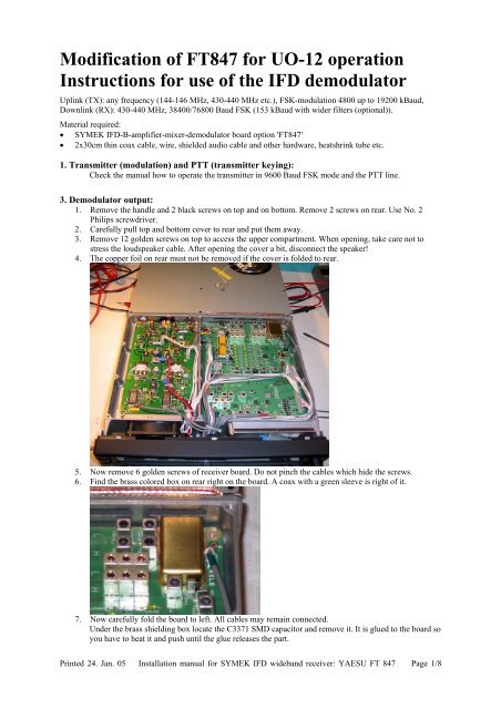
<strong>Modification</strong> <strong>of</strong> <strong>FT847</strong> <strong>for</strong> <strong>UO</strong>-<strong>12</strong> <strong>operation</strong><strong>Instructions</strong> <strong>for</strong> <strong>use</strong> <strong>of</strong> <strong>the</strong> IFD demodulatorUplink (TX): any frequency (144-146 MHz, 430-440 MHz etc.), FSK-modulation 4800 up to 19200 kBaud,Downlink (RX): 430-440 MHz, 38400/76800 Baud FSK (153 kBaud with wider filters (optional)).Material required:• SYMEK IFD-B-amplifier-mixer-demodulator board option '<strong>FT847</strong>'• 2x30cm thin coax cable, wire, shielded audio cable and o<strong>the</strong>r hardware, heatshrink tube etc.1. Transmitter (modulation) and PTT (transmitter keying):Check <strong>the</strong> manual how to operate <strong>the</strong> transmitter in 9600 Baud FSK mode and <strong>the</strong> PTT line.3. Demodulator output:1. Remove <strong>the</strong> handle and 2 black screws on top and on bottom. Remove 2 screws on rear. Use No. 2Philips screwdriver.2. Carefully pull top and bottom cover to rear and put <strong>the</strong>m away.3. Remove <strong>12</strong> golden screws on top to access <strong>the</strong> upper compartment. When opening, take care not tostress <strong>the</strong> loudspeaker cable. After opening <strong>the</strong> cover a bit, disconnect <strong>the</strong> speaker!4. The copper foil on rear must not be removed if <strong>the</strong> cover is folded to rear.5. Now remove 6 golden screws <strong>of</strong> receiver board. Do not pinch <strong>the</strong> cables which hide <strong>the</strong> screws.6. Find <strong>the</strong> brass colored box on rear right on <strong>the</strong> board. A coax with a green sleeve is right <strong>of</strong> it.7. Now carefully fold <strong>the</strong> board to left. All cables may remain connected.Under <strong>the</strong> brass shielding box locate <strong>the</strong> C3371 SMD capacitor and remove it. It is glued to <strong>the</strong> board soyou have to heat it and push until <strong>the</strong> glue releases <strong>the</strong> part.Printed 24. Jan. 05 Installation manual <strong>for</strong> SYMEK IFD wideband receiver: YAESU FT 847 Page 1/8
The IFD has to be inserted in <strong>the</strong> 50 Ohm signal path between <strong>the</strong> balun output and <strong>the</strong> resonanttrans<strong>for</strong>mer circuit. Remove simply <strong>the</strong> coupling capacitor C 3371 (10 nF) and connect a 50 ohmcoaxial to each end <strong>of</strong> <strong>the</strong> removed capacitor.The wire at <strong>the</strong> balun output is marked 'mixer' and goes to IFD input. The o<strong>the</strong>r wire marked 'filter'returns <strong>the</strong> rf from <strong>the</strong> IFD to <strong>the</strong> 50 Ohm input <strong>of</strong> <strong>the</strong> trans<strong>for</strong>mer and <strong>the</strong> quartz filter. Solder <strong>the</strong> shield<strong>of</strong> both cables to a ground plane nearby. Make sure not to short circuit <strong>the</strong> signals unintentionally.Here you see <strong>the</strong> transceiver front end: left side <strong>the</strong> balanced mixer, middle <strong>the</strong> balun with its 50 Ohmoutput and right <strong>the</strong> trans<strong>for</strong>mer which matches <strong>the</strong> 50 Ohm to <strong>the</strong> quartz filter input.Location <strong>of</strong> <strong>the</strong> chip capacitor C3371 on <strong>the</strong> chip side <strong>of</strong> <strong>the</strong> printed circuit board8. Prepare two coax cables: Remove 1.5 cm <strong>of</strong> <strong>the</strong> brown outer insulation. Totally solder <strong>the</strong> outerconductor with much <strong>of</strong> solder and move <strong>the</strong> excess solder to a drop at <strong>the</strong> very end <strong>of</strong> <strong>the</strong> cable. ThePTFE cannot melt. Put <strong>the</strong> cable end on <strong>the</strong> table and gently press a sharp knife to <strong>the</strong> solder filled outerconductor, 5mm away from <strong>the</strong> point where <strong>the</strong> outer brown insulation ends. Turn <strong>the</strong> cable fully roundwhile pressing <strong>the</strong> knife to get a notch in <strong>the</strong> outer conductor. Now try to bent <strong>the</strong> cable back and <strong>for</strong>th,Printed 24. Jan. 05 Installation manual <strong>for</strong> SYMEK IFD wideband receiver: YAESU FT 847 Page 2/8
left and right at <strong>the</strong> point where you have nicked it. The outer conductor will break and can be pulled<strong>of</strong>f easyly. Now <strong>use</strong> <strong>the</strong> knife again to cut <strong>the</strong> inner dielectric. Be carefull not to cut <strong>the</strong> inner conductor.With a wire cutter, pinch <strong>the</strong> inner insulation carefully and find <strong>the</strong> cut. Then pinch <strong>the</strong> wire cutterwithout cutting <strong>the</strong> wire and pull <strong>the</strong> coax to remove <strong>the</strong> inner conductor insulation. Solder <strong>the</strong> innerwire and cut <strong>the</strong> free end to 1.5 mm length.9. It is a good idea to mark <strong>the</strong> both coax cables with color stipes to distinguish later between <strong>the</strong> "mixer"and <strong>the</strong> "filter" cable. Best is to <strong>use</strong> cables with different color insulation (light and dark brown). Wealways <strong>use</strong> <strong>the</strong> brighter color <strong>for</strong> "mixer" and <strong>the</strong> darker color or marking-stripe <strong>for</strong> "filter"10. The (dark) "Filter" cable goes to <strong>the</strong> longer trace in direction to front panel, which passes under R3139and ends on one <strong>of</strong> <strong>the</strong> 7 pads <strong>of</strong> <strong>the</strong> filter T3027 (outside <strong>of</strong> <strong>the</strong> brass box). Best is to solder it to <strong>the</strong>filter pad <strong>for</strong> stability.11. The (bright) "Mixer" cable goes to <strong>the</strong> shorter trace (4mm) leaving C3371 in direction to <strong>the</strong> rear panel.Best is to solder it to <strong>the</strong> thru-hole <strong>for</strong> stability.<strong>12</strong>. For soldering on <strong>the</strong> tiny pads, you need a soldering iron with a fine pointed tip. To solder <strong>the</strong> outerconductor <strong>of</strong> <strong>the</strong> cables to <strong>the</strong> ground, you should <strong>use</strong> a medium size soldering iron with a thick tip andhigher temperature if possible.13. As both cables leave <strong>the</strong> joints in direction to <strong>the</strong> front, bent <strong>the</strong>m so that <strong>the</strong>y can later leave <strong>the</strong> casethrough one <strong>of</strong> <strong>the</strong> slots in <strong>the</strong> rear panel.14. To prevent <strong>the</strong> cables from moving or crossing under <strong>the</strong> board later, solder a bracket to <strong>the</strong> ground padin <strong>the</strong> corner. Use a 1mm copper wire to fix <strong>the</strong> cables15. Solder a red wire to J4005 on <strong>the</strong> PA board. There is already a red wire on this screw terminal where<strong>the</strong> thick 13.8 volt supply cable ends. It needs much heat to solder on this massive terminal!There is NO space in <strong>the</strong> transceiver case to install <strong>the</strong> IFD. Try to install it at <strong>the</strong> rear panel.If you remove <strong>the</strong> loudspeaker, it is possible to install <strong>the</strong> IFD <strong>the</strong>re.16. Feed <strong>the</strong> red cable to <strong>the</strong> lower, rightmost slot <strong>of</strong> <strong>the</strong> rear panel. Also feed both coax cables through thisslot. The cables make a S bent <strong>the</strong>n.17. Slowly re-install now <strong>the</strong> receiver board while gently pulling <strong>the</strong> coax cables until <strong>the</strong> board is down in<strong>the</strong> case again. Make sure all 6 golden screws are tight and push <strong>the</strong> cables back to where <strong>the</strong>y werebe<strong>for</strong>e.18. Close <strong>the</strong> cover now. Do not <strong>for</strong>get to connect <strong>the</strong> speaker be<strong>for</strong>e making all <strong>12</strong> golden screws tight.19. Close <strong>the</strong> black top and bottom cover. The short screws (2x) are <strong>for</strong> bottom to front, <strong>the</strong> long ones (2x)<strong>for</strong> <strong>the</strong> handle and <strong>the</strong> rest (4x) <strong>for</strong> rear and left side.20. The <strong>FT847</strong> looks now exactly as be<strong>for</strong>e. Only three cables on <strong>the</strong> rear haven't been <strong>the</strong>re be<strong>for</strong>e.21. Now prepare a metal box, 62 x 50 x 22 mm inner dimensions. We <strong>use</strong> FR1.6 PCB material and solder<strong>the</strong> edges. Takes lot <strong>of</strong> time but <strong>the</strong> result is a case which fits 100%. Drill four 3.1 mm holes in tob andPrinted 24. Jan. 05 Installation manual <strong>for</strong> SYMEK IFD wideband receiver: YAESU FT 847 Page 3/8
ottom which align with <strong>the</strong> holes <strong>of</strong> <strong>the</strong> IFD board. Drill a 6.5 mm hole in one side <strong>for</strong> a Cynchconnector (Data output). Drill a big (oval) hole in <strong>the</strong> bottom where <strong>the</strong> cables will enter <strong>the</strong> box.Instead <strong>of</strong> <strong>the</strong> Cynch connector at <strong>the</strong> box you may <strong>use</strong> any un<strong>use</strong>d pin <strong>of</strong> one <strong>of</strong> <strong>the</strong> ACC connectors.22. Use a 10 mm M3 screw in <strong>the</strong> bottom holes and install a 4mm hex nut spacer inside <strong>the</strong> box. Theninstall <strong>the</strong> IFD in <strong>the</strong> box and fix it with 4 15mm spacers. The cover <strong>of</strong> <strong>the</strong> box can be fixed with 4screws which fit into <strong>the</strong>se long spacers. It is necessary that <strong>the</strong> length <strong>of</strong> <strong>the</strong> spacers and <strong>the</strong> height <strong>of</strong><strong>the</strong> case match exactly. If <strong>the</strong> spacers would be too long, <strong>the</strong>re is a bad gap between case and cover.23. The external IFD-Box can be easyly fixed to <strong>the</strong> M4 ground screw. If <strong>the</strong> box touches <strong>the</strong> "fin" <strong>of</strong> <strong>the</strong>transceiver case it cannot move or turn, even if it is fixed by a single screw only.BE SURE TO CONNECT YOUR TRANSCEIVER TO GROUND EVENIF THE ORIGINAL GROUND TERMINAL IS NOW OCCUPIED. INSTALL ANALTERNATIVE GROUND CONNECTION FOR SAFETY REASONS!24. Inside <strong>the</strong> box, solder <strong>the</strong> two coax cables to <strong>the</strong> RF IN and RF OUT. Also connect +13.5 V to <strong>the</strong> redwire. Make absolutely sure that <strong>the</strong> correct pin is <strong>use</strong>d as <strong>the</strong> would be a very high current if you shortcircuit <strong>the</strong> supply wire.25. Connect <strong>the</strong> Data Out to <strong>the</strong> cynch connector. – Ready.26. Test: Check if <strong>the</strong> sensitivity <strong>of</strong> <strong>the</strong> receiver is <strong>the</strong> same as be<strong>for</strong>e. There should be no difference.27. Generate a RF signal at 433 MHz, modulated with 1 kHz and up to 40 kHz FM deviation. Thedemodulated signal should be visible on <strong>the</strong> Cynch Data Output using an oscilloscope.Printed 24. Jan. 05 Installation manual <strong>for</strong> SYMEK IFD wideband receiver: YAESU FT 847 Page 4/8
28. Congratulation! Your <strong>FT847</strong> is now ready <strong>for</strong> wide band FSK data reception!29. To connect <strong>the</strong> TNC, make a simple cable to <strong>the</strong> Cynch connector. Inner (Signal) conductor goes topin 4 (Demod) and outer conductor goes to pin 2 (GND <strong>of</strong> TNC). When receiving a 19200, 38400 or76800 baud signal, <strong>the</strong>re will be a perfect eye at <strong>the</strong> data output. The output voltage at 38400 Baud istypically 0.5 volt pp.30. To modulate <strong>the</strong> <strong>FT847</strong>, <strong>use</strong> a standard DIN5 to mini-DIN6 cable <strong>for</strong> 9600 baud. Transmitting on 9600baud requires to switch <strong>the</strong> transceiver to "9600" (No. 25 <strong>of</strong> <strong>the</strong> setup menu, see manual). A middlesetting <strong>of</strong> <strong>the</strong> TNC 9600 baud modem trimmer results in a reasonable deviation. Better <strong>use</strong> a specialdeviation meter <strong>for</strong> alignment (see manual). Adjust <strong>the</strong> output level <strong>of</strong> <strong>the</strong> TNC to get <strong>the</strong> desiredfrequency deviation / modulation index. Do not overmodulate. Note: <strong>the</strong> input voltage determines <strong>the</strong>bandwidth <strong>of</strong> <strong>the</strong> transmit signal.Printed 24. Jan. 05 Installation manual <strong>for</strong> SYMEK IFD wideband receiver: YAESU FT 847 Page 5/8
Questions and Answers:Q: why is <strong>the</strong> IF signal fed through <strong>the</strong> IFD? Wouldn't it be easier to connect <strong>the</strong> IFD in parallel to <strong>the</strong>mixer output?A: directly after <strong>the</strong> mixer, <strong>the</strong> signal passes a quartz filter. As, with every filter, <strong>the</strong> input impedancevaries significantly with frequency: within <strong>the</strong> passband, <strong>the</strong> filter is matched, outside <strong>the</strong> passband, <strong>the</strong>filter reflects <strong>the</strong> signal. The amplitude spectrum at <strong>the</strong> filter input shows a sharp notch at <strong>the</strong> passband.Attaching a parallel demodulator here would ca<strong>use</strong> severe distortions due to <strong>the</strong> varying load. So, <strong>the</strong>signal after <strong>the</strong> mixer has to be buffered. The amplified signal is attenuated again to get <strong>the</strong> same (or afew dB more) signal level as without amplifier.Q: is a AFC output available?A: There is an unconnected pair <strong>of</strong> pins on <strong>the</strong> printed circuit board (M60/M61). These pins can beconnected to <strong>the</strong> joint <strong>of</strong> R52/C52 (DET out) via a 100 kΩ resistor to pin M60. The voltage measured atthis pin will depend on <strong>the</strong> center frequency <strong>of</strong> <strong>the</strong> received FM signal.Q: how do I decode a fast packet-radio signal <strong>of</strong> 38kBaud or more?A: The TNC2 with <strong>the</strong> Z80 processor cannot decode signals beyond 19200 Baud. The newer TNC3 orTNC31 series is capable <strong>of</strong> receive and transmit baudrates up to 1 Mbit/s. There are modems with allcommon baudrates (9600, 19200, 38400, 76800, 153600 and above). Special modems with different RXand TX speed (e.g. TX 9600 / RX 38400 <strong>for</strong> <strong>UO</strong>-<strong>12</strong>) are also available. When using WISP s<strong>of</strong>twarewith a TNC3 packet controller, you may <strong>use</strong> <strong>the</strong> modem 2 <strong>for</strong> receiving and modem 1 <strong>for</strong> transmitting.As WISP <strong>use</strong>s kiss-mode, both modems are received simultaneously, <strong>the</strong> data will be transmitted via <strong>the</strong>default port 1.Q: When receiving a wideband signal, <strong>the</strong> S-meter goes down and <strong>the</strong>re is only noise in <strong>the</strong> loudspeakerbut <strong>the</strong> FSK signal can be decoded properly.A: This in OK beca<strong>use</strong> <strong>the</strong> <strong>FT847</strong> cannot decode such signals. Even <strong>the</strong> S-meter does not measure thissignal: Most <strong>of</strong> <strong>the</strong> bandwidth is cut' by <strong>the</strong> narrow filters <strong>of</strong> <strong>the</strong> receiver. If you reduce <strong>the</strong> deviation <strong>of</strong><strong>the</strong> test signal to zero, <strong>the</strong> S-meter will rise to normal and a clean carrier is heard again.Some notes I made installing <strong>the</strong> Symek IFD on an FT-847..."It works fine, I located <strong>the</strong> IFD in <strong>the</strong> space left vacant after I removed <strong>the</strong> internal speaker. Trust me, it is <strong>the</strong>ONLY space available <strong>for</strong> it. In addition I replaced <strong>the</strong> keyer plug on <strong>the</strong> 847 with <strong>the</strong> full size 5 pin DINexpected by most TNCs, it makes <strong>for</strong> a very clean installation. The IFD stays in <strong>the</strong> circuit at all times, but itdoes not interefere with <strong>operation</strong> at all." - Mark WestFirst thing to say is be very, very, careful!! It's <strong>the</strong> most heart stopping surgery I've ever done on my FT-847: andI've done <strong>the</strong> INRAD filter, <strong>the</strong> headphone volume mod, fitted a new power switch, and a TX expansion mod.The IFD mod makes <strong>the</strong> o<strong>the</strong>r mods look like an walk in <strong>the</strong> park.On <strong>the</strong> face <strong>of</strong> it it doesn't seem a very big deal - all you're doing is tapping into <strong>the</strong> radio's IF, just a couple <strong>of</strong>bits <strong>of</strong> miniature coax. It took me six hours plus a night's rest from start to finish. …The IFD fits on <strong>the</strong> outside <strong>of</strong> <strong>the</strong> radio fairly neatly at <strong>the</strong> rear in a small metal box (not supplied). Trouble is it'sa struggle getting <strong>the</strong> normal PKT and RS232 cables in now as <strong>the</strong> new box gets in <strong>the</strong> way somewhat. I believesomeone's managed to get <strong>the</strong> unit inside <strong>the</strong> FT-847 by removing <strong>the</strong> speaker as an alternative.In conclusion be very very careful! Seems to work a treat now. Haven't <strong>use</strong>d it much on <strong>the</strong> sat as <strong>the</strong>re's hardlybeen a convenient time yet! Talking to myself at 38,400 is very nice (I really should get out more). Netmeetingwith video works a treat at this speeed! I'd be interested in o<strong>the</strong>rs' experiences <strong>of</strong> course. My experience is likelynot indicative <strong>of</strong> a general concensus. 73 Howard G6LVBThe filters F20 and F30 are selected according to <strong>the</strong> desired IF bandwidth:Baudrate FSK IF-Bandwidth AF-Bandwidth Filter type19200 Baud 40 kHz <strong>12</strong> kHz SFE 10.7 MFP or MV38400 Baud 80 kHz 25 kHz SFE 10.7 MT76800 Baud 110 kHz 40 kHz SFE 10.7 MHY-A153600 Baud 230 kHz 80 kHz SFE 10.7 MS2With <strong>FT847</strong>, 35.005MHz quartz (fundamental mode) is <strong>use</strong>d. The IF <strong>of</strong> <strong>FT847</strong> is 10.7 MHz above (45.705MHz)Printed 24. Jan. 05 Installation manual <strong>for</strong> SYMEK IFD wideband receiver: YAESU FT 847 Page 6/8
IFC Option <strong>FT847</strong>IF-Frequency: 45.705 MHz, Filter impedance: 50 Ohm. Acessory parts: 2 pcs thin coax cable (30 cm each)XTAL: 35.005 MHz. Band filter L<strong>12</strong>, L13: 850nH, C10: 82p, C11: 15p, C<strong>12</strong>=C13: 2.7p; C14: 27p, C15: 22p.XO: L80: 1000nH, C80: 47p, C81: 47p, C82: 47p, C86: 33p, R80: none R1=R3=150E, R2=39E.IF-Filter: 76800: SFE 10.7 MHY (red dot, BW110kHz) or <strong>for</strong> 153600: SFE 10.7 MA (light blue, BW230kHz)Supply voltage: <strong>12</strong> volt; supply current: ______ mA, total gain input to output: ________ dBPlot discrimonator output voltage (at R51 / R52) versus input frequency (-80 dBm signal)Plot RSSI output voltage versus input frequency (constant -80 dBm signal)2.82.72.62.52.42.32.22.<strong>12</strong>.01.91.81.71.61.51.41.31.21.11.00.90.80.70.60.5-150 -100 -50 center +50 +100 +15045.550 45.600 45.650 45.700 45.750 45.800 45.850Plot RSSI output volt at M76 vs input (at center frequency). Set to min=0.7V, max=4.3 VVolt4.64.44.24.03.83.63.43.23.02.82.62.42.22.01.81.61.41.21.00.80.60.40.20.0below -140 -130 -<strong>12</strong>0 -110 -100 -90 -80 -70 -60 -50 -40 -30 -20 -10dBm 0date: _____________ sign: _____________________Printed 24. Jan. 05 Installation manual <strong>for</strong> SYMEK IFD wideband receiver: YAESU FT 847 Page 7/8
<strong>Modification</strong>s IFD option FT 847: Oscillator: quartz TQ730518 / 35.005 MHz <strong>for</strong> IF 45.705 MHz, R80: 560Ohm, L80: 0,4 uH, C80: 18pF, C81: 22pF, C82: 27pF. Values <strong>for</strong> <strong>the</strong>band filter: C10: 39pF, C11: 10pF, L<strong>12</strong>: 0,4uH, C<strong>12</strong>: 1.5pF, (C13: 2,7pF), L13: 0,4uH, C14: 18pF, C15: 22pF. R72: 330kOhm, R73: <strong>12</strong>kOhm, R75: 22kOhmBetween joint U1 Pin 3 / R10 and <strong>the</strong> joint C11 / C10 a 22 Ohm resistor was added to reduce influence <strong>of</strong> <strong>the</strong> filter input impedance on amplifier gain. R10 and R11 are changedto 22 Ohm and ano<strong>the</strong>r 22 Ohm resistor is connected in series with C16 to get better 50 Ohm output impedance.Typical voltages (measured wit dc voltmeter):U1 (ERA-3 Amplifier) Pin 1: 2.6 V U2 (IF-IC) Pin 1: 1.1 V U2 (IF-IC) Pin 18: 1.3 VU1 (ERA-3 Amplifier) Pin 3: 3.5 V U2 (IF-IC) Pin 4: 4.2 V U2 (IF-IC) Pin 16: 1.3 VQ 80 (Oscillator) Base 3.2 V U2 (IF-IC) Pin 8: 4.6 V U2 (IF-IC) Pin 14: 1.3 VQ 80 (Oscillator) Emitter 2.8 V U2 (IF-IC) Pin 20: 2.6 V U2 (IF-IC) Pin 11: 1.5 VPrinted 24. Jan. 05 Installation manual <strong>for</strong> SYMEK IFD wideband receiver: YAESU FT 847 Page 8/8