Directley mounted CAN-controls for proportional ... - HAWE Hydraulics
Directley mounted CAN-controls for proportional ... - HAWE Hydraulics
Directley mounted CAN-controls for proportional ... - HAWE Hydraulics

Create successful ePaper yourself
Turn your PDF publications into a flip-book with our unique Google optimized e-Paper software.
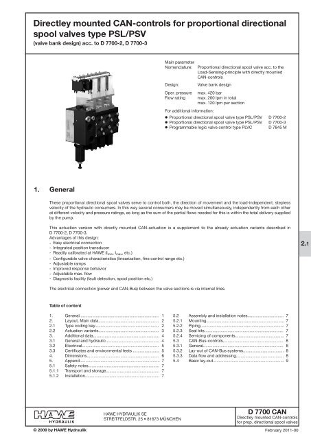
<strong>Directley</strong> <strong>mounted</strong> <strong>CAN</strong>-<strong>controls</strong> <strong>for</strong> <strong>proportional</strong> directionalspool valves type PSL/PSV(valve bank design) acc. to D 7700-2, D 7700-3Main parameterNomenclature:Design:Oper. pressureFlow ratingProportional directional spool valve acc. to theLoad-Sensing-principle with directly <strong>mounted</strong><strong>CAN</strong>-<strong>controls</strong>Valve bank designmax. 420 barmax. 200 lpm in totalmax. 120 lpm per sectionFor additional in<strong>for</strong>mation:' Proportional directional spool valve type PSL/PSV D 7700-2' Proportional directional spool valve type PSL/PSV D 7700-3' Programmable logic valve control type PLVC D 7845 M1. GeneralThese <strong>proportional</strong> directional spool valves serve to control both, the direction of movement and the load-independent, steplessvelocity of the hydraulic consumers. In this way several consumers may be moved simultaneously, independently from each otherat different velocity and pressure ratings, as long as the sum of the partial flows needed <strong>for</strong> this is within the total delivery suppliedby the pump.This actuation version with directly <strong>mounted</strong> <strong>CAN</strong>-actuation is a supplement to the already actuation variants described inD 7700-2, D 7700-3.Advantages of this design:- Easy electrical connection- Integrated position transducer- Readily calibrated at <strong>HAWE</strong> (I min , I max , etc.)- Configurable valve characteristics (linearization, fine control range etc.)- Adjustable ramps- Improved response behavior- Adjustable max. flow- Diagnostic facility (fault detection, spool position etc.)2.1The electrical connection (power and <strong>CAN</strong>-Bus) between the valve sections is via internal lines.Table of content1. General.................................................................... 12. Layout, Main data.................................................... 22.1 Type coding key....................................................... 22.2 Actuation variants.................................................... 33. Additional data......................................................... 43.1 General and hydraulic.............................................. 43.2 Electrical.................................................................. 53.3 Certificates and environmental tests ....................... 54. Dimensions.............................................................. 65. Append..................................................................... 75.1 Safety notes............................................................. 75.1.1 Transport and storage.............................................. 75.1.2 Installation................................................................ 75.2 Assembly and installation notes............................... 75.2.1 Mounting................................................................... 75.2.2 Piping........................................................................ 75.2.3 Seal kits.................................................................... 75.2.4 Servicing of components.......................................... 75.3 <strong>CAN</strong>-Bus-<strong>controls</strong>.................................................... 85.3.1 General..................................................................... 85.3.2 Lay-out of <strong>CAN</strong>-Bus systems................................... 85.3.3 Data flow and addressing......................................... 85.4 Basic lay-out............................................................. 9© 2009 by <strong>HAWE</strong> Hydraulik<strong>HAWE</strong> HYDRAULIK SESTREITFELDSTR. 25 • 81673 MÜNCHEND 7700 <strong>CAN</strong><strong>Directley</strong> <strong>mounted</strong> <strong>CAN</strong>-<strong>controls</strong><strong>for</strong> prop. directional spool valvesFebruary 2011-00
D 7700 <strong>CAN</strong> page 22. Layout, Main data2.1 Type coding keyThe type codings printed bold are detailed in this brochure. For all other details, see D 7700-2 or D 7700-3.Order example:PSV 31/D 170-2 ;-A 2 J 25/25 /EA <strong>CAN</strong>-C/2
D 7700 <strong>CAN</strong> page 32.2 Actuation variantsOrder example:PSV 31/D 170-2-A 2 J 25/25 /EA <strong>CAN</strong>-C/2-A 2 J 25/25 /E <strong>CAN</strong>/2-A 2 J 25/25 /E <strong>CAN</strong>-C/2-E 4-AMP-0-PLVC/250ActuationElectrical actuationDescription Electro-hydraulic Combined with manual actuationCoding E EASuffix <strong>for</strong> <strong>CAN</strong>-<strong>controls</strong>All directly <strong>mounted</strong> <strong>CAN</strong>-<strong>controls</strong> do come with transducer.Basic rule <strong>for</strong> combinations:There must be min. one socket (coding <strong>CAN</strong>-C or <strong>CAN</strong>-T) either at the first or last valve sectionDirectly <strong>mounted</strong> <strong>CAN</strong>-<strong>controls</strong>Description <strong>CAN</strong>-knot incl. socket <strong>CAN</strong>-knot incl. socket <strong>CAN</strong>-knot(at the first or last valve and terminating resistor (all valve sections)section)120 Ω(at the first or last valvesection)Coding <strong>CAN</strong>-C <strong>CAN</strong>-T <strong>CAN</strong>Possible combinations (examples)<strong>CAN</strong>-C - <strong>CAN</strong> - ... - <strong>CAN</strong> - Socket at the first valve section<strong>CAN</strong>-T - <strong>CAN</strong> - …- <strong>CAN</strong> - Socket with terminating resistor at the first valve section<strong>CAN</strong> - <strong>CAN</strong> - …- <strong>CAN</strong>-C - Socket at the last valve section<strong>CAN</strong>-C - <strong>CAN</strong> - …- <strong>CAN</strong>-C - Socket at the first and last valve sectionSocketDescription 4-pin socket 4-pin socket(spec. AMP, with protective circuitry) (spec. SAAB, with protective circuitry)Coding AMP AMSTerminal assignment 1 Power + 1: <strong>CAN</strong>-L2 <strong>CAN</strong>-L 2: Power +3 <strong>CAN</strong>-H 3: Power - / GND4 Power - / GND 4: <strong>CAN</strong>-HSuited plug Co. AMP No. 282 764-1 Co. AMP No. 1-967 059-1<strong>CAN</strong>-protocol- 0 (default)- 1 (customer-specific)Description Protocol Baud rateSpec. <strong>for</strong> communication withspec. in kBaudtype PLVCCoding - PLVC /125- <strong>CAN</strong>open /250 (default)- J1939 /500/1000
D 7700 <strong>CAN</strong> page 43. Additional data3.1 General and hydraulicType codingDesignPSL and PSVDirectional spool valve, valve bank, all-steel designMounting Valve bank: M8; see dimensional drawings in sect. 4Installed positionAnyHydraulic connection P = Pressure inlet (pump) / lead-onR = ReturnA, B = Consumer portsU, W = Load-signal outlet at the indiv. spool valve sectionLS = Load-signal outlet e.g. connection of pump metering valve at PSVM = Pressure gauge port (pump side)Z = Pilot pressure port (20...40 bar inlet, 20 or 40 bar outlet)T = Control oil return portY = Load-signal inlet portPort dimensions dep. on type coding, see D 7700-2, D 7700-3Surface treatmentAll surfaces corrosion-inhibiting, gas nitridedActuation coding suffix E. <strong>CAN</strong> = nickel galvanizedMass (weight) approx. Connection blocks, valve sections, end plates, see D 7700-2, D 7700-3Actuation coding suffix E. <strong>CAN</strong> = +0.3 kgPressure fluid Hydraulic fluid acc. to DIN 51524 table 1 to 3; ISO VG 10 to 68 acc. to DIN 51519Viscosity range: min. approx. 4 mm 2 /sec; max. approx. 1500 mm 2 /secOptimal operation range: approx. 10 ... 500 mm 2 /secAlso suitable are biologically degradable pressure fluids of the type HEPG(Polyalkylenglycol) and HEES (synth. Ester) at operation temperatures up toapprox. +70°C. HETG (e.g. rape seed oil) or water based fluids e.g. HFA or HFC mustnot be used!TemperatureAmbient: approx. -40 ... +80°C;Oil: -25 ... +80°C, pay attention to the viscosity range!Start temperature down to -40°C are allowable (Pay attention to the viscosityrange during start!), as long as the operation temperature during consequentrunning is at least 20K higher.Biological degradable pressure fluids: Pay attention to manufacturer'sin<strong>for</strong>mation. With regard to the compatibility with sealing materials do notexceed +70°C.High temperatures accelerate the aging of electronic components.Rec. contamination class ISO 4406 18/14Operating pressureControl circuitFlowFlow meteringp max = 420 bar; Ports P, A, B, LS, M, Y, U, Wp min = 50 barThe max. pressure achievable at the consumer side of the spool valves is loweredby the amount equivalent of the internal control pressure drop at the 3-way flowregulator of the PSL (see curve)Return port R(R1) ≤ 50 bar; port T pressure less with separate pipe (e.g. 8x1) to thetank, port Z approx. 20 (outlet); ≤ 40 bar (inlet)For control pressure, see Q-I-characteristics.The internal control oil circuit is sufficiently protected against contaminationcaused malfunctions by means of a disk filter.max. consumer flow acc. to the flow rate coding in the type codingAdjustment in 1/1000-steps, linearity ensured via individual calibration of the<strong>CAN</strong>-knots with the correction factors being saved in the control softwareCurves see D 7700-2, D 7700-3
D 7700 <strong>CAN</strong> page 53.2 ElectricalSupply voltage U BCurrent rating I maxCurrent consumption I VSocketProtocol12 – 30 V DCmax. 10 Amax 800 mA at U B = 24 V DC (per valve section)max 1.5 A at U B = 12 V DC (per valve section)AMP = 4-pin AMP-JPTsuited plug Co. AMP No. 282 764-1AMS = 4-pin AMP-JPTsuited plug Co. AMP No. 1-967 059-1Con<strong>for</strong>ming <strong>CAN</strong>open protocol definition DS-301device profile DSP-408 "Device profile fluid power technology <strong>proportional</strong>valves and hydrostatic transmissions"Baud rate see specifications in sect. 2.2<strong>CAN</strong>-Addressing Addressing via identifier, <strong>for</strong> description see sect. 5.33.3 Certificates and environmental testsEMV E1-ECE-directive No. 10 revision 3 - 11 July 2008Protection class IP 67 DIN 40050-9Salt spray test EN 60068-2-11 500 hShock test EN 60068-2-29 25 g, 3-axisOscillation test EN 60068-2-6 5..500 Hz, 2 mm amplitude (5..25 Hz), 5.0 g (25..500 Hz), 3-axisChange of temperature test EN 60068-2-14 -40°C - +85°C (1.5 K/min)Cold test EN 60068-2-1 -40°CDamp/heat test, cyclic EN 60068-2-30 95% moisture, 24 hDry/heat test EN 60068-2-2 85°C, 16 h
D 7700 <strong>CAN</strong> page 64. DimensionsGeneralActuation suffix E.<strong>CAN</strong>-C, E.<strong>CAN</strong>-TActuation suffix E.<strong>CAN</strong>PSL/PSVsize 2PSL/PSVsize 3B49.549.5B139.549.5H99.5110..123H1277303.5H2117.5127.5T79.580B239.549.5Terminal assignment AMP-socket4 Power - / GND3 <strong>CAN</strong>-H2 <strong>CAN</strong>-L1 Power +Accesory:Line connector kit order No 6217 0180-00Terminal assignment AMS-socket1 <strong>CAN</strong>-L2 Power +3 Power - / GND4 <strong>CAN</strong>-HAccesory:Line connector kit order No 6217 0180-00
D 7700 <strong>CAN</strong> page 75. Appendix5.1 Safety notesAll installation, set-up, maintenance and repairs must be per<strong>for</strong>med by authorized and trained staff. The use of this product beyondthe specified per<strong>for</strong>mance limits, use of non specified fluids and/or use of not genuine spares will cause the expiration of theguarantee.The general operating manual <strong>for</strong> mounting initial operation and service of hydraulic components and systems has to beobserved!5.1.1 Transport and storageLike with all hydraulic components attention has to be paid on proper storage and suitable packing of the product.The combination of hydraulic valve and electronic <strong>controls</strong> does not require any special careThe plastic socket must not be mechanically stressed there<strong>for</strong>e it must not be used as handle etc.!5.1.2 InstallationThe following notes, which prevent improper operating conditions have to be taken into account to ensure safe function and a longservice life of the PSL/PSV <strong>CAN</strong> valve knot:- Mounting of the valves nearby machine parts and sub-assemblies which generate great development heat (e.g. exhaust) has tobe avoided.- There must be sufficient distance to radio devices.- An emergency-stop of the power supply has to be provided. The emergency-stop at the machinery must be easily accessible at<strong>for</strong> the operator. The manufacturer of the machine (the vehicle) has to ensure that the machine achieves a sure state after theemergency stop has been actuated- One of the safeguarding mechanisms against bus interruptions, supported by the device, has to be employed. (Nodeguarding,Heartbeat)- The power supply (line and fuse) must be dimensioned sufficiently to cope with the power demand. Each valve section has a max.current consumption of ca. 1.5 A at 12 V DC or 0.8 A at 24 V DC.- The GND-line has to be dimensioned accordingly to the power supply line. The reference potential <strong>for</strong> all <strong>CAN</strong> users should varyas little as possible between the devices and be identical to the GND-connection <strong>for</strong> the power supply.- All valve knots have to be disconnected to any electric welding work.- All sockets of the valve bank have to be safeguarded against penetrating water by proper attachment with installing allnecessary seals.- Use only suited bus lines within the bus network. The lines should be twisted and shielded. The characteristic impedance mustbe approx. 120 Ω.- Terminating resistors of 120 Ω have to be provided on both two ends of the <strong>CAN</strong>-Bus network.- Valve electronics and the respective solenoid body are sealed and are screwed together. There<strong>for</strong>e they should not beseparated. Take care of proper sealing during reassembly when replacing the valve spool or valve body.- A sufficient distance to sources of magnetic fields e.g. strong permanent magnets, eddy-current brakes, etc. has to bemaintained- When the bus and power supply lines are separated from the valve sections <strong>for</strong> servicing it is mandatory to use new lines andseals. Care has to be taken that the end cap is properly positioned. New lines are available at <strong>HAWE</strong>.The following rules have to be observed during operation:- Flawless operation of the <strong>controls</strong> is only guaranteed between -40°C to +85°C.- Only emergency operation is available within a certain temperature range if the device detects internal overheating.- The surface of the solenoid may become hot during operation – danger of burning!- The power supply voltage must be within the specified range. Excessive or permanent deviations may harm the electronics.5.2 Assembly and installation notes5.2.1 MountingThe mounting of the valve bank to the frame or machinery must be per<strong>for</strong>med in such a way that no stress is induced.It is recommended to mount the valve bank via 3 bolts with elastic washers between valve body and frame.5.2.2 PipingOnly fittings with soft seals are to be used.Do not exceed the specified torque ratings.5.2.3 Seal kits Size 2 Size 3Connection block DS 7700-21 DS 7700-31Valve section DS 7700-22 DS 7700-325.2.4 Servicing of componentsValve sections or directly <strong>mounted</strong> <strong>CAN</strong>-<strong>controls</strong> can be only serviced at <strong>HAWE</strong> facilities.
D 7700 <strong>CAN</strong> page 85.3 <strong>CAN</strong>-Bus-<strong>controls</strong>5.3.1 General<strong>CAN</strong>-Bus (controller Area Network) is asynchronous, serial bus system where only two lines are needed <strong>for</strong> the data transmission.Twisted-pair cables with a characteristic impedance of 108 to 132 Ω are recommended as bus line (acc. to ISO 11898-2 "High speedmedium Access Unit").The following protocols are common <strong>for</strong> data transmission <strong>for</strong>mats: <strong>CAN</strong>open 2.0 A & B and J1939, based either on 11 or 29 bitsaddress data.5.3.2 Lay-out of <strong>CAN</strong>-Bus systemsA linear network topology should be employed and tap lines avoided if possible. When tap lines are necessary, their length shouldnot exceed the specifications in table 1.Shielding of the <strong>CAN</strong>-line can be neglected when only low EMC-load is anticipated. The <strong>CAN</strong>-line should be shielded with properGND connection in case of long lines or EMC-contaminated surroundings. A suitable alternative in cable booms is a twistedarrangement of the bus lines.There must not be a potential shift between the individual <strong>CAN</strong> users. GND-lines of all <strong>CAN</strong> devices have to be sufficientlydimensioned and routed together to one single point.The permissible current rating <strong>for</strong> the socket is 10A. Take care that this max current rating of the socket is not exceed, when the busline is patched through a <strong>CAN</strong> PSL/PSV valve bank i.e. when there are an input socket as well as an output socket. In general it isbetter to provide a separate power supply line <strong>for</strong> high load consumers.Transfer rate Bus length Max. length <strong>for</strong> tap lines100 kbit/s 600 m 25 m125 kbit/s 500 m 20 m250 kbit/s 250 m 10 m500 kbit/s 100 m 5 m1000 kbit/s 32, all othercommunication together with the corresponding monitoring and safety functions are maintained by the PLVC.Individual valves are addressed with consecutive indices >2000. The indices of double valves can be calculated by 2000 + 2 n '(n = section No.).Section No. n PLVC ID Knot ID Ref. COB ID Act. COB ID1 2000 32 0x220 0x1A02 2002 34 0x222 0x1A23 2004 36 0x224 0x1A44 2006 38 0x226 0x1A65 2008 40 0x228 0x1A86 2010 42 0x22A 0x1AA7 2012 44 0x22C 0x1AC8 2014 46 0x22E 0x1AE9 2016 48 0x230 0x1B010 2018 50 0x232 0x1B2
D 7700 <strong>CAN</strong> page 95.4 Basic lay-outComponentsCover internal BUSSocket <strong>for</strong> <strong>controls</strong> / power supplyHousing of thevalve <strong>controls</strong>Optional:Socket <strong>for</strong> additional valvebank / <strong>CAN</strong>-userSolenoids