Documentation Part 2 - Sites
Documentation Part 2 - Sites
Documentation Part 2 - Sites

You also want an ePaper? Increase the reach of your titles
YUMPU automatically turns print PDFs into web optimized ePapers that Google loves.
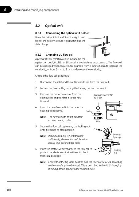
Installing and modifying components 88.2.3 Connecting the optical unit to the systemIf the optical unit has been disconnected from the system, connect it as follows:1 Place the optical unit in the holder.Screw2 Secure it by tightening the screw in theholder.3 Connect the lamp cable to the socket UVLamp on the rear panel of the module.HolderOptical unit4 Connect the signal cable to the socket UV on the rear panel of the module.8.2.4 Connection to the column1 Fix the optical unit directly under the column if possible.Note:Always position the optical unit with the filter wheel cover facingupwards.2 Connect the column outlet tubing directly onto the top ofthe optical unit using a fingertight connector and screw tofinger-tightness.3 Connect the optical unit outlet tubing onto the oppositehole in the flow cell. Use fingertight connectors.If no outlet tubing exists, cut a piece of PEEK tubing (i.d.0.75 mm, o.d. 1/16"). The length should be 170 mm.4 Connect the other end of the tubing to the conductivity flow cell.ÄKTAprime plus User Manual 11-0026-44 Edition AA 101
8 Installing and modifying components8.2.5 Changing the lamp assembly (optional)WARNING! The system uses high intensity ultra-violet light. Do not removethe UV lamp while the system is running. Before replacing a UV lamp, ensurethat the lamp cable is disconnected from the rear of the system to preventinjury to the eyes. If the mercury lamp is broken, make sure that all mercury isremoved and disposed according to national and local environmentalregulations.Lamp housing end plate1 Use a screwdriver to detach the end plate by removing one and looseningthe other of the two holding screws on the lamp housing to be removed.2 Slide the lamp housing off the filter housing.3 Detach the end plate, as in step 1 above, from the lamp housing to be fittedto the optical unit.Dot on lamp housing4 Slide the lamp housing onto the filter housing. The lamp and signal cablesshould be on the same side. As you slide the lamp housing into position,depress the two pressure pads on the filter housing in sequence to facilitatethe installation.Symbols onfilter housing 5 Refit the lamp housing end plate.Symbol onfilter wheelbelow lid6 Slide the lamp housing firmly into place. There will be a faint click when thehousing is positioned correctly. The Hg lamp housing can take up twopositions, one for 280 nm, marked by on the filter housing, and the othermarked by for all other wavelengths. The Zn lamp housing has only oneposition.7 Set the wavelength to be used by selecting lamp position (indicated by a doton the lamp housing) in combination with the appropriate filter, i.e. the dot onthe lamp housing should be adjacent to the symbol on the filter housingcorresponding to the symbol on the filter wheel for the filter to be used. Aclick will indicate that the filter is in position.102 ÄKTAprime plus User Manual 11-0026-44 Edition AA
Installing and modifying components 88.2.6 Changing the filter (optional)The Hg optics with 254 and 280 nm filters and the Zn optics with the 214 nm filterare delivered with filters installed. If other filters are to be used, install them asfollows:1 If the Zn lamp is attached, remove the lamphousing as described in section 8.2.5 Changingthe lamp assembly (optional).2 Remove the four screws in the filter housing.Separate the filter housing from the detectorhousing.3 Carefully remove the filter wheel from the filter housing.4 If necessary, remove the filter(s) from the filter wheel by pressingit (them) out, e.g. with a small screwdriver.TriangularapertureNote:Filters are sensitive optical components. Never touch the opticalsurfaces or expose them to temperatures above 60 °C. Clean themwith dry lens cleaning tissue and store them, when not in use, in thebox in which they were supplied. Heavy contamination may beremoved by using a lens tissue dipped in ethanol.5 Insert the filter(s) of choice into the filter wheel (maximum 3 filters) with thecorrect orientation (the mirror side facing upwards) and position over one ofthe three triangular apertures. The filters snap in by pressing them quitefirmly. Do not touch the filter surface.6 Remove the circular plastic band showing the wavelength(s).7 Remove labels from the band if necessary.o 214o 254o 280o 313o 214o 254o 280o 313o 365o 405o 436o 546o 365o 405o 436o 546280o8 Place the correct labels on the band with the label designation facingoutwards. Ensure that the label position corresponds to the filter position, i.e.the label should be placed opposite the filter.9 Reassemble the circular plastic band with the filter wheel peg fitting into theband notch.10 Check that all filters are clean. Insert the filter wheel back into the filterhousing.Note:The filter wheel can be placed only in one correct position.11 Reassemble the filter housing with the detector housing by fastening the fourscrews.ÄKTAprime plus User Manual 11-0026-44 Edition AA 103
8 Installing and modifying components8.3 Conductivity cellTo install a conductivity cell:HolderConductivitycellUnionLock screwFlowrestrictor1 Connect the conductivity cell to the flow restrictor using the union.2 Insert the cell into the holder and secure it with the lock screw.Note:When the conductivity flow cell is used with the pH electrode, place theconductivity flow cell and select its flow direction so that the screwhead end of the flow cell faces the flow restrictor.3 Connect the conductivity cell to the socket Conductivity Flow Cell on therear panel of the system.4 Connect the tubing with fingertight connectors.8.4 Fraction collector8.4.1 Assembling the tube rackThere are three types of tube racks:Rack Max. no. tubes Tube diam. Tube length12 mm 175 12 mm 50-180 mm18 mm 95 10-18 mm 50-180 mmÄKTAprime plus is delivered with the 18 mm rack mounted. Each rack is made upof a combination of a bowl, tube supports, tube guide and tube holder.The 12 mm rack is available as accessory. Also available for use with the 12 mmtube rack is a double-ended Eppendorf tube holder (18-8522-01). One end holds1.5 ml Eppendorf tubes, the other holds 0.5 ml tubes.104 ÄKTAprime plus User Manual 11-0026-44 Edition AA
Installing and modifying components 8Single cutoutL-shaped cutoutTube HolderTube GuideTube SupportBowlNote that the tube guide has both singleand L-shaped cutouts while the tubeholder only has single cutouts.When assembling a rack, different cutouts are used for the various itemsdepending on the length of the tubes. The cutouts are summarized in the tablesbelow.Tube racks, 12 and 18 mmItem 50-85 mm tubes 85-100 mm tubesTube support L-shaped cutout Not requiredTube guide Single cutout L-shaped cutoutTube holder Single cutout Single cutout1 Insert the tube support, if required, in the bowl.The circular marks on the support should facedown.2 Insert the tube guide with the tube numbersfacing upwards. The guide should rest about1 cm above the support.3 Insert the tube holder, checking that position 1 isdirectly above position 1 in the tube guide. Push the flexible bowl out at eachrib and snap the holder under the top of the rib.ÄKTAprime plus User Manual 11-0026-44 Edition AA 105
8 Installing and modifying componentsDo not force the holder into place as this may damage the lip. The surface ofthe holder should be level.8.4.2 Mounting the tube rack1 Gently move the delivery arm out to the second stop.2 Place the rack over the central spindle and pull the spring loaded drive sleeveout so that the rack comes to rest.Drive sleeve8.4.3 Inserting the collection tubesInsert the sufficient collection tubes into the rack, starting in position 1, pushingeach one down as far as it will go. All the tubes must be of the same length anddiameter, and there should be no empty spaces in the sequence.106 ÄKTAprime plus User Manual 11-0026-44 Edition AA
Installing and modifying components 88.4.4 Adjusting the delivery arm1 Lower the arm and allow it tomove so that the tube sensortouches the collection tubes ofthe outer track.Tube sensor2 Adjust the arm bracket so that the bottom ofthe tube sensor is about 5 mm below the topof the tubes. The tubes should always bebelow the horizontal mark on the tube sensor3 Lock the arm bracket at this height with thelock knob.4 Rotate the rack counter clockwise by hand,until the rear half of the tube sensor restsagainst tube 1. When the fraction collector isstarted, the bowl moves to the correctposition to collect the first fraction in tube 1.Lock knob5 mmSensor control5 Check that the sensor is in the correct position for the tube size. The eluenttubing should be over the centre of the collection tube. Use the red sensorcontrol to position the tube holder.ÄKTAprime plus User Manual 11-0026-44 Edition AA 107
Installing and modifying components 88.5 pH flow cell and electrode (optional)8.5.1 Mounting the flow cell holderIn the ÄKTAprime plus system, the pH electrode is optional.1 Hook the flow cell holder on the right hand side of the housing. Secure it withthe slide clamp.If the flow cell holder is not used, the flow cell must still beinstalled at an angle of 30° from the vertical with theoutlet placed higher than the inlet to prevent air bubblesbeing trapped in the cell.The flow direction is marked on the flow cell.Flow direction2 Connect the tubing with finger-tight connectors.8.5.2 Inserting the pH electrodeNote: Handle the pH electrode with care.CAUTION! The tip of the pH electrode consists of a thin glass membrane.Protect it from breakage, contamination and drying out or the electrode willbe destroyed. Always store the electrode with the end cover filled with a 1:1mixture of pH 4 buffer and 2 M KNO 3 . Do NOT store in water only.1 Unpack the pH electrode. Ensure that it is not broken or dry.2 Before using the electrode, remove the electrode end cover and immerse theglass bulb in buffer for 30 minutes.3 Carefully insert the electrode in the flow cell.Tighten the nut by hand.Note:If the flow cell is full of liquid, it is notpossible to insert the electrode. If so,loosen the inlet connection whileinserting the electrode to allow theliquid to run out from the flow cell.Remember to re-tighten the connector.To systemrear panelElectrodeEndcoverNote:If the electrode is not fully inserted, thesystem will leak and a dead volume willoccur in the holder.4 Connect the pH electrode cable to the socketpH-Probe on the rear of the system.Flow cellholderFlow cellÄKTAprime plus User Manual 11-0026-44 Edition AA 109
l0l08 Installing and modifying components8.6 Recorder REC 112ÄKTAprime plus can be delivered with a recorder, REC 112, for simpler datapresentation. This section describes have to install and use the recorder.8.6.1 Electrical connections1 Make sure that the mains powerswitch is in the OFF position.2 Insert the correct fuses into the fusecaps.Fuse caps(2 pcs.)• For 100–120 V operation, use the 250 mA fuses supplied.• For 220–240 V operation, use the 125 mA fuses supplied.3 Fit the fuse caps into the fuse holder sockets on the left side of the recorder.4 Make sure that the mains voltage selector at the rear of the recorder is set tothe mains voltage of the laboratory.MCMini-DINCAUTION! The mains voltage selector must be set to the mains voltage of thelaboratory. If not, electronics might be damaged.5 Connect the supplied signal cable to ÄKTAprime plus as follows:• The mini-DIN connector to socket Recorder.• The MC connector to socket Rec On/off.The left-hand pin in the socket is the ON/OFF-signal and the right-handpin is signal ground.pH-GroundpH-ProbeDrop Sensor Frac ValveRS-232RecorderRec. On/offConductivity Flow CellUVMainsUV-lampD-subPin connetor110 ÄKTAprime plus User Manual 11-0026-44 Edition AA
Installing and modifying components 86 Connect the pin connectors at the otherend of the cable to the signal input plugssupplied with the recorder.Input 2, signalInput 2, groundNote:The signal cable is delivered withprotective covers on each wire. Donot remove the protective coversfrom unused connections as thismay disturb the measurement.Input 1, signal Input 1, ground7 Connect the plugs to the signal inputs onthe recorder.Pin designations for the signals (and colors on the corresponding cable wire)are as follows:Pin no. Signal 1ChassisgroundRange1 (Brown) Signal 1 0–1 V2 (Red) Signal 1 ground 0 V3 (Orange) Signal 2 0–1 V4 (Yellow) Signal 2 ground 0 V5 (Green) Signal 3 0–1 V6 (Black, thin) Signal 3 ground 0 V7 (Black, thick) Chassis ground 0 V30V max1 The signals have the following default parameter settings:Signal 1 – UV absorbanceSignal 2 – %BSignal 3 – ConductivityThese settings can be changed (see section 8.6.5 Setting analog outputs).8 Connect the D-sub connector to the D-sub socket in the recorder. Pin 12 isthe ON/OFF-signal and pin 15 is signal ground.9 Connect the mains cable to a properly grounded mains socket.WARNING! The system must be connected to a grounded mains socket toprevent system parts from becoming live.10 Turn on the mains power to the recorder.ÄKTAprime plus User Manual 11-0026-44 Edition AA 111
8 Installing and modifying components8.6.2 Loading the chart paper rollTo load the chart paper roll:1 Unpack the paper roll supplied with the recorder and put into place (1.). Makesure the paper roll is positioned so that the printed grid faces the user duringnormal operation.2 Lift the plastic transparent ruler (2.) by pushing it gently upwards so that itrests over the top of the recorder. Leave it in this position.1. 2.3.3 Pull the paper forward. It should be parallel to the housing.4 Use your fingertips to fit the holes in the edge of the paper over the sprockets.Do this on the right-hand side first and then on the lefthand side (3.). This isimportant because the holes in the right side guarantee exact paperpositioning whereas the holes on the left side only support transport.5 When the paper is correctly positioned over both sprocket wheels, hold thepaper in position and lower the ruler.6 Use both hands to gently apply pressure to both the left and right edge of theruler. A double click indicates that the ruler is properly positioned.112 ÄKTAprime plus User Manual 11-0026-44 Edition AA
Installing and modifying components 88.6.3 Installing the pensRecorder REC 112 has a writing system that is very simple and convenient. It usesreliable fibre-tip pens of the disposable cartridge type (1.), which leave a very finetrace and do not bleed.To install the pens:1 Remove the cap.2 Gently push the pen into the plastic pen holder (2.), avoiding sidewards orupwards pressure.Note:To prevent the pens from drying when the recorder is not in use, cover thetips of the pens using the caps provided.2.1.ÄKTAprime plus User Manual 11-0026-44 Edition AA 113
8 Installing and modifying components8.6.4 Preparing the recorder for a run1 Turn on the mains power to the recorder.2 Set the zero keys (4) to the down position.3 Select a suitable low chart speed (0.5–2 mm/min) with the chart speedselector (8) and the mm/s–mm/min key (9).4 Set both pens (6) to position down. Use the adjust knob (5) to make a coarsezero adjustment to the right-hand zero on the chart.5 Set rec. (7) to position on and make a final zero adjustment.6 Set rec. to position off. Use the forward feed key (11, 12) to align the shortnibpen with a grid line and press the set key (13), i.e. set start position.7 Set the zero keys to the up position.8 Select a suitable chart speed (2–20 mm/min) according to the length of thepurification.9 Select 1 V with the range V/mV selector (1).10 The recorder is made ready to use by setting the rec. key to on. The chartpaper starts rolling when the run starts.114 ÄKTAprime plus User Manual 11-0026-44 Edition AA
Installing and modifying components 88.6.5 Setting analog outputsThe Set Analogue Out menu is used to select which measurement parameterthat should be associated to each channel. The menu is also used for settingmeasurement parameters (zero and full range values) for UV, Cond, pH and Presson the analogue output channels.Set ParametersSet Analogue Out1 Select the Set Parameters menu in the main menu and press OK.2 Select the Setup Analogue Out menu and press OK to enter the settingsmenu.Set Rec Out 1(UV)Setting parameters for the channelsUV, pH, conductivity, concentration of buffer B, temperature and pressure aremeasurement parameters that can be associated to the analogue outputchannels.1 When entering the Setup Analogue Out menu, the setting for channel 1 isdisplayed first. Press the up and down buttons to display the settings forchannels 2 and 3.Set Rec Out 1 (UV)UV pH Cond %B Tmp Pr2 Select the desired channel and press OK. In this example, channel 1 isselected.3 Select the desired parameter and press OK.Note:The analogue output level for Tmp has a fixed set value; 0 °C correspondsto 0 V and 50 °C corresponds to 1.0 V.Set UV Analogue Out(0.005AUFS 10%)Set UV Zero Level(10.0%) 10.0Setting the UV analogue output1 Select the Set UV Analogue Out menu in the Setup Analogue Out menu byusing the up and down buttons. Current analogue settings are displayed(zero and full range values). Allowed full range values are 0.0001, 0.0002,0.0005, 0.001, 0.002, 0.005, 0.01, 0.02, 0.05, 0.1, 0.2, 0.5, 1.0, 2.0 and 5.0. Zerolevel is set as a percentage of full scale.2 Press OK to access the settings menu. The current setting is displayed. PressOK.3 Set the desired zero level value. Press OK to acknowledge.Set UV Range(0.005AUFS) 0.00024 Press the down button to access the settings menu. The current setting isdisplayed. Press OK.5 Set the desired full range value. Press OK to acknowledge.ÄKTAprime plus User Manual 11-0026-44 Edition AA 115
8 Installing and modifying componentsSet Cond Analogue Out(00.00-50.00mS/cm)Set Cond Zero Level(0.00mS/cm) 0.00Setting the Cond analogue output1 Select the Set Cond Analogue Out menu in the Setup Analogue Out menuby using the up and down buttons. Current analogue settings are displayed(zero and full scale values).2 Press OK to access the settings menu. The current setting is displayed. PressOK.3 Set the desired zero level value. The range is 0.000–999.9 mS/cm. Press OK toacknowledge.Set Cond Full Scale(50.00mS/cm) 50.004 Press the down button to access the next settings menu. The current settingis displayed. Press OK.5 Set the desired full scale value. The range is 0.000–999.9 mS/cm. Press OK toacknowledge.6 Press Esc to return to the Set UV Analogue Out menu.Setting the pH analogue outputNote: The pH values for zero level and full scale must differ by at least 1 pH unit.Note:The zero level and full scale values can be calibrated in any order.Set pH Analogue Out(pH 0.00-14.00)Set pH Zero Level(pH 0.00) 00.00Set pH Full Scale(pH 14.00) 14.001 Select the Set pH Analogue Out menu in the Setup Analogue Out menu byusing the up and down buttons. Current analogue settings are displayed(zero and full scale values).2 Press OK to access the settings menu. Press OK.3 Set the desired zero level value. The range is pH -0.50–14.30.Press OK to acknowledge.4 Press the down button to access the next settings menu. Press OK.Set Press. Analogue Out(1.00 MPa) 1.005 Set the desired full scale value. The range is pH -0.50–14.30.Press OK to acknowledge.6 Press Esc to return to the Set UV Analogue Out menu.Setting the Press analogue output1 Select the Set Press Analogue Out menu in the Setup Analogue Out menuby using the up and down buttons. The current analogue setting is displayed(full scale value).Set Press. Analogue Out(2.00 MPa) 2.002 Press OK to access the settings menu. Set the desired full scale value. Therange is 0.00–1.00 MPa. Press OK to acknowledge.116 ÄKTAprime plus User Manual 11-0026-44 Edition AA
Installing and modifying components 88.6.6 Printing curves directly after a runSelected run data is usually printed directly during the run. However, if a re-printof the result is desired, this can be done as a post-run print-out. This procedure isdescribed below.The system has three analog output channels for printing the run data curvesafter the run. You can choose to print out UV absorbance, pH, conductivity,theoretical gradient (%B), temperature or pressure.Memory Print Out?(yes)yes noWhen the run is completed, or if it has been aborted, the prompt Memory PrintOut? is displayed.1 To print out the run data, select yes.Otherwise, select no.Set Rec Out 1 (UV)UV pH Cond %B Tmp PrSet Rec Out 2 (UV)UV pH Cond %B Tmp PrSet Rec Out 3 (UV)UV pH Cond %B Tmp PrAutoscaling(no) yes no2 At the Set Rec Out 1 menu, select the parameter to be printed on channel 1.Press OK.3 At the Set Rec Out 2 menu, select the parameter to be printed on channel 2.Press OK.4 At the Set Rec Out 3 menu, select the parameter to be printed on channel 3.Press OK.5 If auto-scaling of the UV-curve is required, select yes.Otherwise, select no.6 Press the set key on the recorder to define the start position for the print-out.7 Press OK to print the curves.ÄKTAprime plus User Manual 11-0026-44 Edition AA 117
8 Installing and modifying components8.6.7 Printing curves before the next runThe system stores the run data from the latest run. Therefore, post-run print-outcan be done either at the end of the run as described in the precious section, orbefore the next run using the Set Parameters menu as described below.1 Set the rec. key on the recorder to off.2 Press the home key to get the paper back to the start position.3 Increase the chart speed value about ten times. This is due to that the curvesare printed ten times faster at the post-run print-out than during the actualrun.4 Set the rec. key to on to enable the print-out.5 Set the pen key to position down.Set Parameters6 Select main menu Set Parameters and press OK.Memory Print Out7 Select menu Memory Print Out and press OK.Print out toRecorderComputer8 At the Print out to menu, select Recorder and press OK.9 Select the desired parameters to be printed as in steps 2–5 on page 117.The print-out will now overlay the previous curves.10 Repeat the procedure above to select other parameters and print out thecurves.More information about the recorder is found in the Recorder REC 112 UserManual supplied.118 ÄKTAprime plus User Manual 11-0026-44 Edition AA
Maintenance 99 MaintenanceThis chapter contains a periodic maintenance schedule and instructions formaintenance, replacing components, and calibrations.9.1 Periodic maintenanceRegular maintenance will help to keep your ÄKTAprime plus running smoothly.Follow the recommendations in this chapter to keep the system in good workingorder.WARNING! Remove liquid or dirt from the system surface using a cloth and, ifnecessary, a mild cleaning agent.WARNING! Always disconnect the power supply before attempting to replaceany item on the system during maintenance.WARNING! If there is a risk that spilt liquid have penetrated the casing of theinstrument and come into contact with the electrical components,immediately switch off the system and contact an authorised servicetechnician.WARNING! When using hazardous chemicals, take all suitable protectivemeasures, such as wearing protective glasses and gloves resistant to thechemicals used. Follow local regulations and instructions for safe operationand maintenance of the system.WARNING! When using hazardous chemicals, make sure that the entiresystem has been flushed thoroughly with bacteriostatic solution, e.g. NaOH,and distilled water before service and maintenance.WARNING! NaOH is injurious to health. Avoid spillage.WARNING! Only spare parts that are approved or supplied by GE Healthcaremay be used for maintaining or servicing the system.WARNING! Use ONLY tubings supplied by GE Healthcare to ensure that thepressure specifications of the tubings are fulfilled.ÄKTAprime plus User Manual 11-0026-44 Edition AA 119
9 MaintenanceWARNING! If the system is turned, the external capillaries and other tubingmay become entangled in nearby objects and be pulled from theirconnections causing leakage.9.1.1 Preventive maintenance scheduleIntervalDailyActionSystem • Inspect the complete system for eluent leakage.• The system can be left filled with buffer overnight. If you are notusing the separation unit for a few days:1. Wash the flow path with distilled water.2. Remove the column and the pH electrode (optional).3. Wash the flow path with 20% ethanol and store it in 20%ethanol. Make sure that all tubing and all flow paths usedare rinsed.Pump • Check for leakage. If there are signs of liquid leaking from the pump:– Check the tubing connections.– Check the O-rings in the connection part. Replace theO-rings if necessary.• If there are signs of erratic or pressure pulsation, flush the pumpwith 100% methanol and then with distilled water.pH electrode • Calibrate the pH electrode according to the section Calibrating thepH electrode (optional).Every weekInlet filters • Check the inlet filters visually and replace them if necessary.Every monthMonitor • Check the monitor according to section 9.5.Flow restrictor • Check that the flow restrictor generates the following back-pressure:0.2 ± 0.05 MPa.Check the back-pressure as follows:1. Disconnect the flow restrictor2. Connect a capillary to port 1 of the injection valve.3. Run the pump manually at 10 ml/min with water. Note thebackpressure on the display.4. Connect the flow restrictor to the open end of the capillary.5. Run the pump at 10 ml/min with water. Note the backpressureon the display.6. Calculate the backpressure generated by the flowrestrictor. Replace it if it is not within limit.120 ÄKTAprime plus User Manual 11-0026-44 Edition AA
Maintenance 9IntervalEvery 6 monthsor more often if requiredActionMonitor • Clean the UV flow cell according to section 9.9 or 9.10.• Change the pH electrode. Refer to section 8.5.Fraction collector • Check the drive sleeve on the tube rack. Replace if worn.• Check the number of tube shifts according to section 9.7.Superloop • Check that the top, bottom and moveable seal O-rings are in goodcondition. Replace if necessary.• Check that the bottom end pieces are clean and undamaged.Mixer • Check that the mixer chamber is clean and without damage.• Check the tubing connectors. Replace if required. Refer to section9.17.YearlyInjection valve and buffer valve • Check for external or internal leakage.Replace channel plate and distribution plate when required. Refer tosection 9.13.Every 2 yearsMixer • Replace the complete mixing chamber. Refer to section 9.17.Superloop • Replace O-rings. Refer to section 4 in the instruction supplied withSuperloop.When requiredMonitor • Clean the conductivity flow cell according to section 9.11.• Clean the pH electrode flow cell according to section 9.18.Pump • Replace the check valve O-rings according to section 9.16.• Clean the check valves. If necessary, replace the check valve O-ringsor the entire check valves according to section 9.16.9.2 Cleaning the system• Wipe the surface regularly with a damp cloth. Do not allow spilt liquid to dryon the instrument.• Remove dirt from the surface using a cloth and a mild cleaning agent.• Let the system dry completely before using it.ÄKTAprime plus User Manual 11-0026-44 Edition AA 121
9 Maintenance9.3 Cleaning the system flow pathWARNING! When using hazardous chemicals, make sure that the entiresystem has been flushed thoroughly with bacteriostatic solution, e.g. NaOH,and distilled water before service and maintenance.Section 9.3.3 Monthly cleaning describes how to flush the system with abacteriostatic solution.Usually the column should be by-passed with a piece of i.d. 0.75 mm PEEKcapillary before cleaning the system flow path. If not, make sure that the columnwithstands the expected flow and pressures.For column cleaning procedures and storage instructions, please refer to thecolumn instructions.9.3.1 Betweens runsBuffers not containing any salt can be left in the system for a short time after arun, even overnight (not in the pH electrode, see instructions below).If a buffer containing salt has been used, the flow path should be flushed withdeionized water. This is especially important if an organic solvent will be used inthe next run.To flush the flow path:1 Fill a syringe with five times the sample loop volume of deionized water.2 Rinse the sample loop by injecting the water through the fill port on theinjection valve.3 Put all used inlet tubings in water4 In the Templates menu, select Application Template and then SystemWash Method.5 Select the used inlet ports. Inlets A1 and B will always be washed.6 Press OK to start the method. The system flow path is automatically flushed.122 ÄKTAprime plus User Manual 11-0026-44 Edition AA
Maintenance 99.3.2 Weekend and long-term storageCAUTION! Never leave the pH electrode in the electrode holder for any periodof time when the system is not used, since this may cause the glassmembrane of the electrode to dry out. Store the pH electrode fitted in the endcover filled with a 1:1 mixture of pH 4 buffer and 2 M KNO 3 . Do NOT store inwater only!If you are not using the system for a few days or longer:1 Wash all tubing and flow paths used with deionized water, for example byrunning the System Wash Method with all tubing inlets in water.2 Replace the column with a bypass capillary.3 Replace the pH electrode (optional) with a dummy pH electrode.4 Wash the system with 20% ethanol and store it in 20% ethanol.The UV flow cell can also be stored dry by flushing as above with distilled waterand then 20% ethanol through the flow cell. Replace the red protective caps.Never use compressed air as this may contain droplets of oil.pH electrode (optional)The pH electrode should always be stored in a 1:1 mixture of pH 4 buffer and2 M KNO 3 when not in use. After removing the pH electrode from the flow cell,insert a dummy electrode in the flow cell.9.3.3 Monthly cleaningWARNING! NaOH is injurious to health. Avoid spillage.Clean the system every month, before service and maintenance, or whenproblems, such as ghost peaks occur. The system is cleaned as follows:1 Disconnect the column and replace it with a suitable capillary.2 Put all tubing inlets in 1 M NaOH.3 Run System Wash method for all inlet tubings.4 Flush the whole system with 1 M NaOH for 20 minutes (1 ml/min).5 Immediately repeat steps 3 and 4 with distilled water to rinse the system ofNaOH.ÄKTAprime plus User Manual 11-0026-44 Edition AA 123
9 Maintenance9.3.4 Other cleaning considerationsAfter repeated separation cycles, contaminating material may progressivelybuild up in the system and on the columns. This material may not be removed bythe cleaning step described above. The nature and degree of contaminationdepends on the sample and the chromatographic conditions employed.9.4 Moving the systemCAUTION! Never lift the system by the components mounted on the systemchassis.WARNING! When using hazardous chemicals, make sure that the entiresystem has been flushed thoroughly with bacteriostatic solution, e.g. NaOH,and distilled water before service and maintenance.WARNING! If the system is turned, the external capillaries and other tubingmay become entangled in nearby objects and be pulled from theirconnections causing leakage.Before moving the system, ensure that all cables and capillaries connected toperipheral equipment and liquid containers are disconnected.Lift the system by placing your fingers in the gap between the base and the workbench surface, grasping firmly and lifting.9.5 Checking the UV monitorCheck Lamp IntensityR 215.5 S 214.7mV9.5.1 Checking lamp intensity1 Select menu Check and press OK.2 Select menu Check Lamp Intensity.If:R
Maintenance 9Check Lamp Run TimeHg 2300h Zn 340h9.5.2 Checking lamp run time1 Select menu Check and press OK.2 Select menu Check Lamp Run Time.• The lifetime of a Hg lamp at 254 nm is typically 7000 hours in roomtemperature (in coldroom, typically 2000 h).• The lifetime of a Hg lamp at 280 nm is typically 3500 hours in roomtemperature.• The lifetime of a Zn lamp is typically 2000 hours in room temperature.When necessary, replace the lamp assembly according to section 8.2.5Changing the lamp assembly (optional), or contact GE Healthcare for lampreplacement.9.5.3 Checking autozeroThe internal absorbance value for autozero can be checked to test theconsistency of buffers.1 Select menu Check and press OK.Check AutozeroAZ 0.0001 AU2 Select menu Check Autozero. The autozero absorbance value for thewavelength used is shown.9.6 Checking the pump9.6.1 Checking pump run time1 Select menu Check and press OK.Check Pump Run Time00014h2 Select menu Check Pump Run Time.The lifetime of the wearing parts (glass tube, piston, sealings andO-rings) is typically 2000 hours at normal use.When necessary, contact GE Healthcare for replacement.9.6.2 Checking pumped volume1 Select menu Check and press OK.Check Pumped volume194529452ml2 Select menu Check Pumped Volume.When required, contact GE Healthcare for replacement.ÄKTAprime plus User Manual 11-0026-44 Edition AA 125
9 Maintenance9.7 Checking the fraction collectorCheck Tube Shifts175649.7.1 Checking tube shifts1 Select menu Check and press OK.2 Select menu Check Tube Shifts.When required, contact GE Healthcare for replacement.Check Valve ShiftsBV:17564 IV:281439.8 Checking the rotary valves1 Select menu Check and press OK.2 Select menu Check Valve Shifts.The value after BV shows the number of buffer valve shifts. The value after IV thenumber of injection valve shifts. One shift means the shifting between twoadjacent positions. The lifetime of the valves is > 50 000 shifts.When necessary, replace the plates according to section 9.13 Replacing plates inthe rotary valves, or contact GE Healthcare for sealing replacement.9.9 Cleaning the UV flow cell in-placeWARNING! NaOH is injurious to health. Avoid spillage.Pump a cleaning or sanitizing agent through the flow cell. The standardrecommendation is to pump 1 M NaOH for 30 minutes and then wash outimmediately with buffer.9.10 Cleaning the UV flow cell off-lineA clean flow cell is essential for correct operation of the UV monitor.CAUTION! Do not allow solutions that contain dissolved salts, proteins orother solid solutes to dry out in the flow cell. Do not allow particles to enter theflow cell as damage to the flow cell may occur.1 Connect a syringe to the inlet of the flow cell and squirt distilled waterthrough the cell in small amounts. Then fill the syringe with a 10% surfaceactive detergent solution like Decon 90, Deconex 11, RBS 25 or equivalent,and continue to squirt five more times.2 Leave the detergent solution in the flow cell for at least 20 minutes.126 ÄKTAprime plus User Manual 11-0026-44 Edition AA
Maintenance 93 Pump the remaining detergent solution through the flow cell.4 Rinse syringe and flush the flow cell with distilled water (10 ml).9.11 Cleaning the conductivity flow cell off-lineWARNING! NaOH is injurious to health. Avoid spillage.If the conductivity measurements are not comparable to previous results, theelectrodes in the flow cell may be contaminated and require cleaning. To cleanthe flow cell:1 Pump 15 ml of 1 M NaOH at 1 ml/min through the flow cell either by using thesystem pump or a syringe.2 Leave for 15 minutes.3 Rinse thoroughly with degassed distilled water.Note:If the flow cell is totally blocked, the blockage can be removed using aneedle or a wire with a diameter less than 0.8 mm.9.12 Replacing the conductivity cellThe conductivity flow cell can be replaced when required. Make sure the systemis switched off before connecting/disconnecting the cell from the rear of thesystem.If the cell is replaced with a new flow cell, the system must be calibrated with thenew cell constant written on the flow cell package. See section 9.20.3 Calibratingconductivity. If the cell constant is not known, it can be determined.ÄKTAprime plus User Manual 11-0026-44 Edition AA 127
9 Maintenance9.13 Replacing plates in the rotary valvesA replacement kit for each valve is available. Refer to 11.5 Ordering information.ChannelplateDistributionplate3Injection valveBuffer valve1 Make sure that the valve is in position 1 (see figure) and then disconnect alltubings.2 Remove the four screws on the front using a 3 mm hex wrench. Loosen eachone equally in turn so that the distribution plate comes off parallel to thevalve body.3 Slide the screws out.4 Remove the distribution plate containing the ports.5 Remove the old channel plate and insert the new one.6 Remount a new distribution plate so that the text 3 (injection valve) or i/o(buffer valve) is horizontal and to the right of the central tubing connection.Using a hex wrench, tighten the four screws in turn, a little at a time, until thedistribution plate is fixed to the valve body.128 ÄKTAprime plus User Manual 11-0026-44 Edition AA
Maintenance 99.14 Removing and assembling the pumpThe connection part should be removed to allow access to the check valves andthe O-rings.9.14.1 Removing the connection partBefore disassembling the pump, move the input liquid bottle below the level of thepump to prevent siphoning.1 Turn off the system with the mains power switch.2 Disconnect the inlet and the outlet tubingfrom the connection part.3 Release the pump from the system.4 Unscrew the two attachment screws usinga 4 mm hex wrench.5 Remove the connection part.Connection partScrews9.14.2 Installing the connection part1 Wipe the back of the connection part and the other parts behind theconnection part with a clean cloth.2 Check that none of the seven O-rings on the rear side of the connection parthas come loose.3 Fit the connection part in position. Fasten the two attachment screws usingthe 4 mm hex wrench.4 Reconnect the inlet and the outlet tubing.5 Purge the pump carefully and check that the fault is corrected. See section5.2.2 Purging pump and inlet tubing.ÄKTAprime plus User Manual 11-0026-44 Edition AA 129
9 Maintenance9.15 Replacing O-rings in the pump9.15.1 Required spare parts• O-ring kit (see Ordering information for code no.)9.15.2 Replacing an O-ringTo replace an O-ring:1 Remove the connection part according tosection 9.14.1 Removing the connectionpart.2 Remove the faulty O-ring carefully to avoidmaking scratches on the connection part.3 Fit the new O-ring in position.4 Reinstall the connection part according tosection 9.14.2 Installing the connection part.O-ring (x7)9.16 Cleaning and replacing check valves in the pumpFaulty operation of the check valves is usually indicated by irregular flow, verylow flow, or unstable pressure traces. Probable causes are air, dirt, or a damagein a check valve preventing it from closing to seal and hold the pressure. Liquidappearing at a banjo fitting might indicate that a check valve O-ring is damaged.9.16.1 Required spare parts• Check valve (there are four different check valves. See Ordering informationfor code nos.)• O-ring kit (see Ordering information for code no.)9.16.2 Cleaning the check valves in-placeTry to clean the check valves in-place by pumping 100% ethanol forapproximately 10 min. If this does not correct the problem, follow the instructionsbelow to remove and then clean the valves. If necessary, a check valve or O-ringsmight need to be replaced.130 ÄKTAprime plus User Manual 11-0026-44 Edition AA
Maintenance 99.16.3 Removing the check valvesIf the condition of the check valve is not improved by in-place cleaning, remove itas follows:1 Remove the connection part according to section 9.14.1 Removing theconnection part.2 The check valves in the connectionpart are locked in position with banjofittings. Remove the check valvesusing the screwdriver.Check valve9.16.4 Cleaning the check valves off-line1 Immerse the check valves in 100% ethanol and place in an ultrasonic bathfor 5–10 minutes.2 Repeat the ultrasonic bath with distilled water.9.16.5 Replacing the check valve O-ringsLiquid appearing at a banjo fitting might indicatethat a check valve O-ring is damaged. It might alsocause reduced flow or pressure fluctuation.Carefully replace both O-rings on the check valvewith new ones if you suspect that an O-ring is damaged.O-ring9.16.6 Installing the check valvesIf cleaning of the check valve as described in section 9.16.4 Cleaning the checkvalves off-line does not correct the fault, replace the check valve with a new one.Note:Make sure that the check valves are installed in their correct positions. Bymistake, an inlet check valve can be installed incorrectly in an outlet checkvalve position, and vice versa.The check valves are of four different types:– Inlet check valve short (1 pc.)– Inlet check valve long (2 pcs.)– Outlet check valve short (2 pcs.)– Outlet check valve long (1 pc.)ÄKTAprime plus User Manual 11-0026-44 Edition AA 131
9 MaintenanceThe inlet check valves have line-shaped holes.The outlet check valves have round holes.Inlet check valve longLine-shapedholesInlet check valve shortOutlet check valve longRoundholesOutlet check valve shortTo install a check valve:1 Carefully insert the check valve fully.Note:Make sure that the inlet check valves are installed next to the inlet(lower) port on the connection part, and the outlet check valves next tothe outlet (upper) port.2 Fasten the check valve using the screwdriver.3 Reinstall the connection part according to section 9.14.2 Installing theconnection part.132 ÄKTAprime plus User Manual 11-0026-44 Edition AA
Maintenance 99.17 Replacing mixer chamberWARNING! When using hazardous chemicals, make sure that the entiresystem flow path has been flushed thoroughly with distilled water beforemaintenance.1 Make sure the pump is stopped.2 Place the buffer bottles lower than themixer to prevent draining, and thenremove the inlet and outlet tubing.3 Open the chamber lock holding themixer chamber. A spring is securing thechamber in position when the lock isopened.4 Pull out the mixer chamber gently.5 Move the stop plug to the right-handinlet of the new mixer chamber.Chamber lockOutletSpringLeft-hand inletRight-hand inlet26 Insert the new mixer chamber and close the lock.7 Replace the inlet and outlet tubing.ÄKTAprime plus User Manual 11-0026-44 Edition AA 133
9 Maintenance9.18 Cleaning the pH electrode (optional)Note:The pH electrode has a limited lifetime and should be replaced every sixmonths, or when the response time is slow or the slope is out of range(
Maintenance 99.20 CalibrationsFollow the calibration schedule below to maintain accurate measurements.ComponentPumpPressure offsetConductivity flow cellCell constantTemperatureEntering a new cellconstantpH electrode (optional)How oftenOnly necessary after replacing spare parts.When required.Only necessary if specific conductivity with highaccuracy is measured.Must be done when changing the flow cell.Must be done when changing the flow cell.Every dayThe calibrations are made in the Setup and calibrations menu.Set ParametersSetup andcalibration9.20.1 Calibrating the pumpCalibrating the flow rateCalibrate the pump after replacing spare parts.1 Make sure no bubbles are trapped in the flow path.2 Immerse the inlet tubing A1 in a vessel filled with degassed buffer.3 Place the waste tubing from port 5 on the injection valve in an empty vessel(the flow will automatically be diverted to port 5 during the calibration).Start Pump Calibr.800 pulsesSet Flow Rate(10 ml/min) 2.0Enter CollectedVolume (ml) 2.054 Select Start Pump Calibration in Setup and calibration menu. Press OK.5 Enter the intended flow rate as calibration flow rate and press OK.6 Measure the volume of the water collected in the vessel.7 Enter the measured volume in ml in the Enter Collected Volume menu andpress OK.8 At the Pump Calibrated OK menu press OK.ÄKTAprime plus User Manual 11-0026-44 Edition AA 135
9 Maintenance9.20.2 Calibrating the pressure sensorCalibrating the pressure offsetThe zero pressure should be calibrated when required.1 Make sure that the pressure sensor is exposed to atmospheric pressure only,i.e. no backpressure.Change Press Offset(1005 mV)Set zero pressureto calib. Press OK2 Select the Change Press Offset menu in the Setup and calibration menu.Press OK.3 At the Set zero pressure to calib. menu press OK.The calibration only takes a few seconds.4 Press OK at the Calibrating Offset Done! menu.9.20.3 Calibrating conductivitySet up adjust cell constantAfter replacing the flow cell, the cell constant has to be set. The cell constant iswritten on the cell packaging.Set Parameters1 From the main menu, select menu Set Parameters and press OK.Setup andcalibrationSetup Cond2 Select sub menu Setup and calibration and press OK.3 Select sub menu Setup Cond and press OK.Set Adj Cell Const(83.56cm -1 )Warning! This willchange cell calibr.Set Adj Cell Const(83.56cm -1 ) 83.554 Select sub menu Set Adj Cell Const. The current cell constant is shown. PressOK.5 A warning message is shown until confirmed by pressing OK.The current cell constant is displayed as default. Enter the new cell constantas read from the packaging and press OK. The range is 0.1–300.0 cm -1 .136 ÄKTAprime plus User Manual 11-0026-44 Edition AA
Maintenance 9Set up adjust conductivityNormally, it is not necessary to adjust the cell constant because the flow cell ispre-calibrated on delivery. Adjustment is only necessary when replacing theconductivity flow cell with a flow cell whose cell constant is unknown. Werecommend that the conductivity flow cell is recalibrated after cleaning.Note:The conductivity temperature compensation must not be used whenadjusting the cell constant. Set the Set Cond Temp Comp to 0 (see page138). The temperature sensor must be calibrated before adjusting the cellconstant (see page 139).1 Prepare a calibration solution of 1.00 M NaCl, 58.44 g/l. Let the solution standuntil it is at room temperature. This is important for exact measurements.2 Fill the flow cell completely with the calibration solution by pumping at least15 ml through the cell with a syringe.3 Stop the flow and wait 15 minutes until the temperature is constant in therange 20–30 °C.4 Read the conductivity value displayed and compare it with the theoreticalvalue from the graph below at the temperature of the calibration solution. Ifthe displayed value and the theoretical value correspond, no further actionis required.If the values differ, proceed with the actions below.ÄKTAprime plus User Manual 11-0026-44 Edition AA 137
9 MaintenanceSet ParametersSetup andcalibrationSetup CondSet Adjust Cond(80.32mS/cm)Warning! This willchange cell calibr.5 From the main menu,select menu SetParameters and press OK.6 Select sub menu Setupand calibration and pressOK.7 Select sub menu SetupCond and press OK.8 Select sub menu SetAdjust Cond. The currentconductivity value isshown. Press OK.9 A warning message isshown until confirmed bypressing OK.Conductivity (mS/cm)Conductivity of 1.00 M NaCl at 20–30°C97959085Set Adjust Cond(80.32mS/cm) 83.5510 The current value isdisplayed as default. Enterthe theoreticalconductivity valueaccording to the graph andpress OK. The new cellconstant is automaticallycalculated. The range is1.000–999.9 mS/cm.807720 25 30Temperature (°C)Set ParametersSet up conductivity temperature compensation1 From the main menu, select menu Set Parameters and press OK.Setup andcalibrationSetup Cond2 Select sub menu Setup and calibration and press OK.3 Select sub menu Setup Cond and press OK.Set Cond Temp Comp(0.0%)Set Cond Temp Comp(0.0%) 0.04 Select sub menu Set Cond Temp Comp and press OK. The currenttemperature compensation factor is shown. 0.0% means that thecompensation is off (default setting). The range is 0.0–9.9%.5 The current compensation factor is displayed as default. Adjust thecompensation factor setting as necessary and press OK.138 ÄKTAprime plus User Manual 11-0026-44 Edition AA
Maintenance 9Set ParametersSet up conductivity reference temperature1 From the main menu, select menu Set Parameters and press OK.Setup andcalibrationSetup Cond2 Select sub menu Setup and calibration and press OK.3 Select sub menu Setup Cond and press OK.Set Cond Ref Temp(25.0°C)4 Select sub menu Set Cond Ref Temp and press OK. The current referencetemperature value is shown. 25 °C is the default setting. The range is 0.00–99.9 °C.Set Cond Ref Temp(25.0°C) 25.05 The current reference temperature value is displayed as default. Adjust thereference temperature value setting as necessary and press OK.9.20.4 Calibrating the temperature sensorCalibration of the temperature sensor in the conductivity flow cell is onlynecessary if the monitor is used in high accuracy measurement or if theconductivity flow cell is replaced.1 Place the flow cell together with a precision thermometer inside a box orempty beaker to ensure that they are not exposed to draught. Leave themfor 15 minutes to let the temperature stabilize.2 Read the temperature on the thermometer.Set Parameters3 From the main menu, select menu Set Parameters and press OK.Setup andcalibrationSetup Temp4 Select sub menu Setup and calibration and press OK.5 Select sub menu Setup Temp and press OK.Set Adjust Temp(25.0°C)Warning! Temp calibrwill be changed.Set Adjust Temp(25.0°C) 25.06 Select sub menu Set Adjust Temp. The current temperature is shown. PressOK.7 A warning message is shown until confirmed by pressing OK.The current adjustment value is displayed as default. Enter the temperatureshown on the thermometer and press OK.ÄKTAprime plus User Manual 11-0026-44 Edition AA 139
9 Maintenance9.20.5 Calibrating the pH electrode (optional)A good laboratory routine is to calibrate the pH measurement once a day, whenthe electrode is replaced or if the ambient temperature changes. The pHelectrode is calibrated using standard buffer solutions in a two point calibration.The two buffer solutions can have any pH value as long as the difference betweenthem is at least 1 pH unit. The calibration procedure can be done with the pHelectrode either fitted in or removed from the flow cell.Calibrating with the electrode outside the flow cellWhen calibrating the electrode out of the flow cell and changing from one bufferto another, rinse the electrode tip with distilled water and dab it carefully with asoft tissue to absorb the remaining water. Do NOT wipe the electrode as this maycharge it and give unstable readings.The steps below describe the procedure used with the electrode removed fromthe flow cell.1 Remove the pH electrode from the flow cell and immerse the electrode in thefirst standard buffer solution (normally pH 7.0).Set ParametersSetup andcalibrationSetup pH2 From the main menu, select menu Set Parameters by pressing the up or thedown button. Press OK.3 Select menu Setup and calibration. Press OK.4 Select menu Setup pH and press OK.Calibrate pH(7.00 - 12.00)5 Select menu Calibrate pH. Current calibration values are displayed (buffer 1– buffer 2).Buffer 1 = fixed lower calibrated pH value. Range=0.00-14.00Buffer 2 = fixed higher calibrated pH value. Range=0.00-14.00Note:The values for buffer 1 and 2 must differ by at least 1 pH unit.Calibrate pH Buffer 16 Press OK to access the settings menu. The order of calibration, buffer 1 orbuffer 2, is optional. Press OK to start with buffer 1, or press the down buttonto start with buffer 2. In this example, we start with buffer 1.Calibrate pH Buffer 1(7.00) Please wait!7 This text disappears when the reading is stable and the following text is thenshown:Calibrate pH Buffer 1(7.00) 7.00140 ÄKTAprime plus User Manual 11-0026-44 Edition AA
Maintenance 98 Adjust the pH value in the display with the up and down buttons so that itcorresponds to the known pH value of the first buffer solution. Press OK.Calibrate pH Buffer 2Calibrate pH Buffer 2(9.00) Please wait!Calibrate pH Buffer 2(9.00) 9.009 At the buffer 2 calibrating menu, rinse the electrode tip with distilled waterand then immerse the electrode in the second buffer solution (e.g. pH 4.0 or9.0). Then press OK.10 The text opposite disappears when the reading is stable and the text belowis then shown.11 Adjust the pH value in the display with the up and down buttons so that itcorresponds to the known pH value of the second buffer solution. Press OK.Calibrated ElectrodeSlope 98.5% 9,5 mV12 After the calibration with buffer2, the system automaticallyenters the Calibrated Electrodemenu. This menu shows theslope of the calibration curve,where 100% corresponds to59.16 mV per pH step at 25°C.The asymmetry potential at pH7 is shown as a mV value. PressEsc repeatedly to return to theSet Parameters menu.+500 mVAsymmetrypotentialat pH 70 mV–500 mVVoltage (mV)The calibration curveshows the relationshipbetween pH and theoutput signal from themonitor in mV.7pHCalibration curve13 Before use, rinse the electrode using distilled water.A new electrode typically has a slope of 95–102% and an asymmetry potentialwithin ±30 mV. As the electrode ages, the slope decreases and the asymmetrypotential increases.As a rule, when an electrode has an asymmetry potential outside ±60 mV and aslope lower than 80%, and no improvement can be made by cleaning, theelectrode should be changed.An electrode is still usable at lower slopes and higher asymmetry potentials butthe response will be slower and the accuracy diminished.Calibrating with the electrode in the flow cellWhen calibrating with the electrode fitted in the flow cell, follow the aboveprocedure but let at least 30–35 ml (with 2 ml mixer) of standard buffer solutionbe pumped through the system to stabilize pH. Leave the pump running whilecalibrating. Switch to the second standard buffer solution and repeat theprocedure.ÄKTAprime plus User Manual 11-0026-44 Edition AA 141
9 MaintenanceSet up pH temperature compensationThe relationship between pH and the output signal from the pH electrode istemperature dependent. For accurate measurements during temperaturechanges, the pH measurement can be temperature compensated. In normalapplications, when the temperatures of the buffers and calibration buffers areidentical, temperature compensation is not necessary.When using temperature compensation, it is important that the temperature ofthe pH electrode is the same as that of the conductivity flow cell since that iswhere the temperature is measured.Set Parameters1 From the main menu, select sub menu Set Parameters and press OK.Setup andcalibrationSetup pH2 Select sub menu Setup and calibration. Press OK.3 Select sub menu Setup pH and press OK.Set pH Temp Comp(off)Set pH Temp Comp(off) on off4 Select sub menu Set pH Temp Comp. The current setting for showing pH isdisplayed. If on is shown, Tc is displayed in the running display. If off is shown(default), Tc is not displayed. Press OK to change the setting.5 Select the desired setting and press OK.142 ÄKTAprime plus User Manual 11-0026-44 Edition AA
Troubleshooting 1010 Troubleshooting10.1 Faults and actionsThis section lists faults observed with specific monitor measurements and thespecific components. The faults are listed as follows:TypeIf the suggested actions do not correct the fault, call GE Healthcare.PageSystem . . . . . . . . . . . . . . . . . . . . . . . . . . . . . . . . . . . . . . . . . . . . . . . . . . . . . . . . . . . . . . . . . 144UV curve . . . . . . . . . . . . . . . . . . . . . . . . . . . . . . . . . . . . . . . . . . . . . . . . . . . . . . . . . . . . . . . . . 145Conductivity curve . . . . . . . . . . . . . . . . . . . . . . . . . . . . . . . . . . . . . . . . . . . . . . . . . . . . . . . . 146pH curve (optional) . . . . . . . . . . . . . . . . . . . . . . . . . . . . . . . . . . . . . . . . . . . . . . . . . . . . . . . 147Pressure curve. . . . . . . . . . . . . . . . . . . . . . . . . . . . . . . . . . . . . . . . . . . . . . . . . . . . . . . . . . . . . . 144Pump . . . . . . . . . . . . . . . . . . . . . . . . . . . . . . . . . . . . . . . . . . . . . . . . . . . . . . . . . . . . . . . . . . . . 148Mixer . . . . . . . . . . . . . . . . . . . . . . . . . . . . . . . . . . . . . . . . . . . . . . . . . . . . . . . . . . . . . . . . . . . . . 148Fraction collector . . . . . . . . . . . . . . . . . . . . . . . . . . . . . . . . . . . . . . . . . . . . . . . . . . . . . . . . . . . . 149Buffer valve and injection valve . . . . . . . . . . . . . . . . . . . . . . . . . . . . . . . . . . . . . . . . . . . . . 149ÄKTAprime plusV 3.00When contacting GE Healthcare for support, state the program version of thesystem, which is shown for a few seconds during start-up.WARNING! The system should not be opened by the user. It contains highvoltage circuits that can deliver a lethal electric shock.ÄKTAprime plus User Manual 11-0026-44 Edition AA 143
10 TroubleshootingFault10.2 SystemActionNo text on the front display 1 Check that the mains cable is connected and that the poweris turned on.10.3 Pressure curveFaultPressure limit exceeded, inaccuratereadingIrregular flow, noisy baseline signal,irregular pressure traceAction1 Calibrate the pressure monitor.2 Check that inlet or outlet tubings are not clogged. Replace ifnecessary.3 A check valve in the pump might be clogged or damaged.Remove the check valve according to section 9.14. Clean thecheck valve in an ultrasonic bath. If the leakage persists,replace the assembly.Air bubbles passing through or trapped in the pump.1 Check that there is sufficient eluent in the reservoirs.2 Check all connections for leakage.3 Use degassed buffers.4 Remove any air bubbles according to section 10.13.Blockage or partial blockage of the flow path1 Flush the flow path to clear the blockage.2 If necessary, replace the tubing.3 Check the inlet tubing filter.4 A check valve in the pump might be clogged or damaged.Remove the check valve according to section 9.14. Clean thecheck valve in an ultrasonic bath. If the leakage persists,replace the assembly.144 ÄKTAprime plus User Manual 11-0026-44 Edition AA
Troubleshooting 10Fault10.4 UV curveActionNoisy UV-signal, signal drift or instability 1 Select menu Check Autozero to check the autozeroabsorbance value. If the value is between 1.5 and 2, theremay be air bubbles in the flow cell, or the wrong buffersystem is in use.2 Wrong filter for the lamp is being used. Check that the lamp isin the proper position and that the correct filter is used.3 The buffer may be impure. Check if the signal is still noisy withwater.4 There may be air in the flow cell. Check that the flow restrictorgenerates a back-pressure of 0.2 ±0.05 MPa. Replace it if thisis not within the limits.5 If there is a lot of air in the water, degas the buffer before use.6 Check the connections of the optical unit.7 Clean the UV flow cell, see sections 9.9 and 9.10.8 Locking nut in optical unit not properly tightened. Turn thelocking nut to the stop position.9 Air bubbles trapped in the pump. Refer to section 10.13.Ghost peaks 1 Check that there is no air in the eluent. If necessary, degas theeluent2 Clean the system in accordance with section 9.3.3 Clean the column in accordance with the column instructions.4 Check that the mixer is functioning properly and that thecorrect chamber volume is being used.5 Unless you are using a low pressure column, try using a flowrestrictor FR-904 instead of FR-902. This generates a higherback-pressure (0.4 MPa instead of 0.2 MPa).Low sensitivity 1 Aging lamp. Check the lamp and replace if necessary.2 Wrong lamp position. Check that the lamp position and thewavelength used (filter position) fit together.Error in external chart recorder 1 Check the recorder according to the manufacturer’sinstructions.ÄKTAprime plus User Manual 11-0026-44 Edition AA 145
10 TroubleshootingFault10.5 Conductivity curveActionIncorrect or unstable reading 1 Check that the conductivity flow cell cable is connectedproperly to the rear of the system.2 Check that the pump operates properly.3 If temperature compensation is being used, check that thetemperature sensor is calibrated, and that the correctcompensation factor is used.4 Check that the column is equilibrated. If necessary, clean thecolumn.5 Check the operation of the mixer.Baseline drift or noisy signal 1 There may be air in the flow cell. Use a flow restrictor after theflow cell and check that the flow restrictor gives a backpressureof 0.2 ±0.05 MPa.2 Check for leaking tubing connections.3 Check that the column is equilibrated. If necessary, clean thecolumn.4 Check the operation of the mixer and the pump.5 Clean the flow cell according to the procedures insections 9.11.Conductivity measurement with thesame buffer appears to change overtime1 Clean the flow cell according to the procedures insections 9.11.2 The ambient temperature may have changed. Use atemperature compensation factor.Waves on the gradient 1 Check that the pump and the valves are operating properlyand are programmed correctly.2 Change to a larger mixing volume if necessary.3 Check the operation of the mixer.Absolute conductivity value is wrong 1 Turn the flow cell so the end with screws faces the pH flowcell.2 Recalibrate the conductivity cell.3 Calibration solution, 1.00 M NaCl, not correctly prepared.Prepare a new calibration solution and recalibrate theconductivity cell.Ghost peaks appear in the gradientprofileNon-linear gradients or slow responseto %B changes1 A charged sample has been detected (e.g. protein).2 Air bubbles are passing through the flow cell. Check for loosetubing connections. If necessary, use a flow restrictor afterthe conductivity cell.1 Check that the tubing has been washed properly and that thepump is operating.2 Change to a smaller mixer volume.146 ÄKTAprime plus User Manual 11-0026-44 Edition AA
Troubleshooting 10Fault10.6 pH curve (optional)ActionIncorrect/unstable pH reading 1 Check that the electrode cable is connected properly to rearof the system.2 Check that the pump operates properly.3 Check that the electrode is correctly inserted in the flow celland, if necessary, hand-tighten the nut.4 If air in the flow cell is suspected, tap the flow cell carefully ortilt it to remove the air. Alternatively, flush the flow cell withbuffer at 20 ml/min for 30 s. Use a flow restrictor after the pHelectrode.5 Check that the pH electrode is not broken.6 Check that the pH electrode is calibrated.7 Check the slope. If it is outside the range 80–105% or if theasymmetry potential deviates more than ±60 mV from 0 mV,clean the pH electrode. Recalibrate. If the problem persists,replace the pH electrode.8 Clean the pH electrode if required (see section 9.18).9 Compare the response of the pH electrode with that ofanother pH electrode. If the response differs greatly, theelectrode may require cleaning or replacement.10 There may be interference from static fields. Connect thepH flow cell to the rear of the system using a standardlaboratory 4 mm “banana plug” cable.11 Check that the pH electrode has been calibrated at thecorrect temperature.12 In organic solvents such as ethanol, methanol andacetonitrile, stable pH measurements are not possible sincedehydration of the membrane will occur. We recommend thatthe pH electrode is not used in applications using organicsolvents.13 Clogged liquid junction. Refer to section 9.18.No response to pH changes 1 Check that the electrode cable is connected properly to rearof the system.2 The electrode membrane may be cracked. If so, replace theelectrode.Small response to pH changes 1 Clean the pH electrode according to section 9.18 andrecalibrate.2 If the problem persists, replace the pH electrode.ÄKTAprime plus User Manual 11-0026-44 Edition AA 147
10 TroubleshootingFaultSlow pH response or calibrationimpossiblepH values vary with varied backpressureAction1 Check the electrode glass membrane. If it is contaminated,clean the electrode according to the instructions in section9.18.2 If the membrane has dried out, the electrode may be restoredby soaking it in buffer overnight.3 Clogged liquid junction. Refer to section 9.18.1 Replace the pH electrode.Fault10.7 MixerActionLeakage 1 Check the tubing connections. Retighten or replace ifnecessary.2 Check the mixer chamber. Replace if liquid has penetrated themixer chamber walls and sealings.Fault10.8 PumpActionIrregular flow 1 Check the inlet and outlet tubings.2 Remove any air bubbles according to section 5.2.2.3 If still irregular flow, calibrate the pump according to section9.20.1.4 A check valve in the pump might be clogged or damaged.Remove the check valve according to section 9.14. Clean thecheck valve in an ultrasonic bath. If still irregular flow, replacethe assembly.Leakage 1 An O-ring in a check valve or in the connection part might bedamaged. Examine the O-rings. If necessary, replace themaccording to the section 9.15.2 or 9.16.5.148 ÄKTAprime plus User Manual 11-0026-44 Edition AA
Troubleshooting 10Fault10.9 Fraction collectorActionNo tube change 1 Press the feed tube key. If the motor does not start and anerror appears, call GE Healthcare.2 Push the delivery arm out to a safety stop. Press the feedtube key. If the motor starts, press the tube sensor togetherwithin 2 seconds. The motor should stop without an errorcode reported.If an errors appears, check the connection in the arm. If this iscorrect, the sensor or sensor connection are faulty. Call GEHealthcare.Tubes skipped 1 The spring tension may be insufficient. Perform the actionsdescribed in section 10.12.Drop synchronization is not functioning 1 Check that the drop synchronization function is turned on.See section 11.2.1.2 The drop sensor photocell located above the tube sensor isdirty. Clean the photocell with a damp cloth.3 Make sure that the fraction collection tubing is properlyconnected to the delivery arm. See section 8.4.510.10 Buffer valve and injection valveFaultActionThe valve is switching to wrong position The valve parts may have been incorrectly reassembled afterreplacement.1 Check that the distribution plate marking i/o (buffer valve) or 3(injection valve) is horizontal.External leakage 1 Check the tubing connections. Tighten or replace if required.Internal leakageInternal leakage can be detected at the small hole on theunderside of the valve body.1 Internal parts may be worn. Change channel plate anddistribution plate according to section 9.13.High back-pressure 1 Perform cleaning-in-place by flushing the system withdetergent.1 Change channel plate and distribution plate according tosection 9.13.ÄKTAprime plus User Manual 11-0026-44 Edition AA 149
10 Troubleshooting10.11 Error messagesIf the suggested actions do not correct the fault, call GE Healthcare.Messages34 Start up failedRetry/Call service35 WARNING wrongaveraging time set50 Electrical errorCall for serviceAction1 Perform a new start-up. The preceding message may tell more about thecause2 If not, call service.1 Wrong value for averaging time set. See section 11.2.1.1 Call for service.57 Electrical errorCall for service75 Electrical errorCall for service60 Tube switchalways active61 No more tube isavailable62 Check that the tubeposition is OK64 ERROR No dropscheck sensor65 ERRORPump failure66 Too short timebetween feeds67 ERROR Injectionvalve failure68 ERROR Buffervalve failure1 Check that the fraction collector is not stuck.2 Check the tube indicator.3 If the problem remains, call service.1 Put more tubes in the fraction collector.1 Check that a tube in the fraction collector touches the tube indicator.2 Check the cable to the tube indicator.3 If the problem remains, call service.1 Check the cable to the tube indicator.2 Check that it is dripping. If it flows continuously, reduce the flow or turn offthe Drop sync function.3 If the problem remains, call service.1 Restart the system.2 If the problem remains, call service.1 Reduce the flow or increase the fraction size.1 Call service.1 Call service.150 ÄKTAprime plus User Manual 11-0026-44 Edition AA
Troubleshooting 10Messages69 ERROR Stop grad.set HOLD or PAUSE70 Lamp disconnectedIf not, call service71 WARNING low lightintensity72 Change lamp orcall service76 Change lamp orcall service73 WARNING Too muchstraylight leaks in77 WARNING Autozeroout of range78 ERROROver pressure79 ERROR Methodcorrupt in eeprom80 ERRORReading from eeprom81 ERRORWriting to eeprom82 ERROR Parameterfail in method83 WARNING temp_calwill be changedAction1 Set the system in HOLD or PAUSE, or stop the gradient (%B).1 Connect the lamp or call service.1 Check the cables to the optical unit.2 Check that lamp and filter position correspond.3 Change lamp. If the problem remains, call service.1 If used in cold room, additional warm-up might be needed.2 If the problem remains, change the lamp.3 If the problem remains, call service.1 Check that the filter wheel cover is closed.2 Check that non-transparent tubings are used at the UV flow cell inlet andoutlet.3 Check that the optical unit is not exposed to direct sunlight.4 If the problem remains, call service.1 Autozero is not allowed on a level above 2 AU.2 Check buffers.3 Clean UV flow cell.1 Re-program the method.1 Check which method is corrupted (erased).2 If the problem remains, call service.1 Call service1 Call service.1 Re-program the method.1 Press OK to accept change.2 Press ESC to skip the change.84 WARNING cond_calwill be changedÄKTAprime plus User Manual 11-0026-44 Edition AA 151
10 TroubleshootingMessages85 WARNING conscale(0-100%)
Troubleshooting 10Messages99 ERROR Out ofmethod memoryERROR keyERROR Number 102-104ERROR Number 109-113Action1 Maximum number of breakpoints in memory is 600. Delete a method to getmore memory.1 A key was pressed during self-test, or is faulty.2 Switch off the system.3 Switch on the system.1 Switch off the system.2 Check all connections.3 Switch on the system.ERROR Number 119-121Exc x/y in ab.cExc DIV/0 in ab.c1 Switch off the system.2 Check all connections.3 Switch on the system.Exc instr in ab.cExc address in ab.cÄKTAprime plus User Manual 11-0026-44 Edition AA 153
10 Troubleshooting10.12 Adjusting the spring tension of the delivery armIncorrect spring tension can cause the fraction collector to skip tubes. The effectis greater as the arm moves towards the centre.Spring tension is temperature sensitive. Low temperature, for example in a coldroom, reduces the spring tension so it may be necessary to adjust the tension.1 Remove the arm bracket from the stand.2 Dismantle the delivery arm from the bracket.3 The top of the spring is fastened in one of two holes in the top of the armbracket.Looking at the arm bracket from the front of the unit, moving the spring fromthe right hand to left hand hole increases the tension, and conversely movingfrom the left hand to the right hand hole decreases the tension.Hold the spring near the top and pull or prise it down and out of the top hole.Insert the spring in the other hole.4 The bottom of the spring is fastened in one of four holes, equally spaced 1/4turn apart. To adjust the bottom of the spring, hold it near the lower end andlift or prise the bottom of the spring out of the hole.• To increase the tension turn the spring counter-clockwise.• To decrease the tension turn the spring clockwise.10.13 Removing trapped air bubblesIf there are large amounts of air in the tubing or if you suspect air in the pump,purge the flow path as described in section 5.2.2.10.14 Restart after power failureIf the power to the system is interrupted, it automatically restarts when power isrestored and displays the main operating menu. All set values and the data fromthe latest run are retained, and the lamp is switched on.154 ÄKTAprime plus User Manual 11-0026-44 Edition AA
Reference information 1111 Reference information11.1 System descriptionplusÄKTAprime plus is a compact separation unit comprising components for fluidhandling and for measuring UV-absorption, conductivity andpH (optional).This section gives a brief description of the system and its components. It alsodescribes optional components that may be connected to the system.A built-in power control board supplies the components with power, and acontroller handles the communication between the components via an internalhigh speed network.ÄKTAprime plus User Manual 11-0026-44 Edition AA 155
11 Reference information11.1.1 Components descriptionThe following illustration shows the location of the components in the system.FractioncollectorMonitor andcontrollerColumnholderFlowdiversionvalveSample loopLCD displayPush buttonsplusColumnUV flow cellPumpFlowrestrictor 2PressuresensorMixerInjectionvalveBuffervalveSwitch valveFlowrestrictor 1ConductivitycellBuffer valveThis is a rotary valve which has 8 positions. The valve has a360° rotating channel plate. As the plate is turned by themotor, the central port on the front is connected to one ofthe peripheral ports 1–8, allowing a clear liquid path. Thevalve switching is controlled by the system by reading theactual position of the channel plate.Central port1 82i/o376The buffer valve is used on the low pressure side in the flowpath (before the pump). It it used for switching betweensample and buffer solutions.45Peripheral portThe switching parts are made of PEEK, which ensures long mechanical andchemical lifetime.156 ÄKTAprime plus User Manual 11-0026-44 Edition AA
Reference information 11Switch valve/ Flow diversion valveThis is a 3-port/2-way valve, supplied with24 V DC. It has one permanently open portmarked COM and two ports marked NC(normally closed) and NO (normally open).Port COM may be used as an inlet or anoutlet port.NCCOMINACTIVENONCCOMACTIVENOThere are two switch valves in the system; one is used for gradient formation andthe other one for flow diversion during fractionation.PumpThe pump is equipped with a single input and double outputs (only one is used). Itcontains three internal plunger pumps which in combination with check valvescreate a smooth flow from the pump. The pump delivers flows up to 50 ml/minand pressures up to 1.0 MPa.In the connection part, the inlet and outlet flow paths are split into three separateflow paths – one to/from each plunger pump chamber. All six flow paths areequipped with non-return check valves.Outlet portCheck valve(x6)ConnectionpartPlunger pumpchamber (x3)Leakage holeInlet portThe plungers pump the liquid through the chambers while the check valvesprevent the liquid from flowing backwards. The pump phases of three plungerpumps are displaced by 120° which results in a sequential motion of the plungerpumps, and thereby a smooth liquid delivery.Leakage between the connection part and the pump chambers is prevented byO-rings. Any leakage behind the plungers is diverted through the drainage hole inthe front of the connection part. The check valves are also equipped with O-rings.The pump is equipped with automatic speed control to reduce pulsation and withpressure compensation.ÄKTAprime plus User Manual 11-0026-44 Edition AA 157
11 Reference informationPressure sensorThe pressure in the system is continuously measured by the pressure sensorlocated next to the pump. The pressure is shown on the display during the run. Amaximum pressure limit can be set to protect the column.MixerThis is a dynamic, single chamber mixer with interchangeable mixer chambers.The system is delivered with a 2 ml chamber.The eluents are mixed in two steps:1 Premixing in a static mixer with a small volume (22 µl).222 Dynamic mixing in a chamber with a rotating stirrer.A mixer motor inside the system spins a magnet at 600 rpm, whichcauses the stirrer in the mixing chamber to rotate.1For optimal gradients at high flow rates, a larger mixer chamber is required. Othermixer chambers with 0.6, 5 and 12 ml mixer volumes are available as accessories.When using eluents that are more difficult to mix, such as isopropanol and water,or if the pH and conductivity readings indicate uneven mixing of your buffers(unstable readings) a larger mixer volume will give better mixing.Injection valveA 7-port motorized rotary valve is used as sampleinjection valve. It has a valve body with a rotatingcentral core, the channel plate. As the channel plate isrotated by the motor, different ports are connected.3The valve has three different operating positionswhich make it possible to:• Load a sample loop without disturbing column equilibration.• Wash the sample loop while the column is in operation.• Wash the pump for eluent exchange without disturbing the column.TocolumnFromsyringe•LOAD, pos 1 INJECT, pos 2 WASTE, pos 32413576FrompumpTocolumnFromsyringe2413576FrompumpTocolumn2341576FrompumpWasteWasteWaste158 ÄKTAprime plus User Manual 11-0026-44 Edition AA
Reference information 11The geometry of the valves ensures that the flow path is completely swept so thatsolvent or sample “memory effect” is virtually non-existing. The switching partsare made of PEEK, which ensures both long mechanical and chemical lifetime.MonitorThis is a high precision on-line monitor for handling measurement data from theUV optical unit, the conductivity cell and the pH electrode (optional). Incombination with the flow cells, the monitor offers fixed wavelengths of 214 nm(Zn-lamp, optional), 254 and 280 nm (Hg-lamp), fast response, high accuracy andreproducibility, and low dead volumes.UV optical unitThe UV optical unit houses the lamp (Zn or Hg), thewavelength filter and the UV flow cell. There are two flowcells available; optical path length 2 mm or 5 mm(optional). The type of flow cell used depends on thesample amount applied and the size of the column.UV flow cells with 2and 5 mm path lengthsThe light beam from the lamp is directed through a double conical or a straightflow-through cuvette (6 µl or 2 µl illuminated volume). The photodetector currentis fed to the signal processing circuitry inside the system.The reference signal comes from the same point in the lamp as the signalmeasuring the sample, thus assuring a stable baseline by eliminating the effectsof variations in lamp intensity.Optical UnitInletFilterLens Beam splitter Flow cellPhotodetectorLampPhotodetectorOutletVrVsSystem housingFront panelHigh voltagepower supplyMicroprocessorÄKTAprime plus User Manual 11-0026-44 Edition AA 159
11 Reference informationThe Hg lamp emits light only at certain wavelengths. It does not emit light at 280nm, so for this wavelength, the light is converted at a fluorescent surface beforeit passes the filter. On the lamp housing, there is a special exit for 280 nm light,which means that the lamp position needs to be changed when working with thiswavelength.For 214 nm wavelength, a Zn lamp is used. This lamp is larger than the Hg lampand is therefore mounted in a larger lamp housing.The lamp connectors are keyed to inform the monitor software which lamp typeis connected.Conductivity flow cellThe flow cell has two cylindrical titanium electrodes positioned in the flow path ofthe cell. An alternating voltage is applied between the electrodes and theresulting current is measured and used to calculate the conductivity of the eluent.The monitor controls the AC frequency and increases it with increasingconductivity between 50 Hz and 50 kHz giving maximum linearity and trueconductivity values.The conductivity is automatically calculated by multiplying the measuredconductance by the flow cell’s cell constant. The cell constant is pre-calibrated ondelivery but can be measured with a separate calibration procedure. Thisprocedure is described in section 9.20.3 Calibrating conductivity.One of the electrodes has asmall temperature sensor formeasuring the temperature ofthe eluent in the flow cell.Temperature variationsinfluence the conductivity and,in some applications whenEluentTemperaturesensorhighly precise conductivity values are required, it is possible to program atemperature compensation factor that recalculates the conductivity to a setreference temperature.160 ÄKTAprime plus User Manual 11-0026-44 Edition AA
Reference information 11Flow restrictor FR-902There are two flow restrictors in the system, each generating a backpressure of0.2 MPa. One is connected to port 5 on the injection valve to prevent bufferdrainage when the injection valve is in position WASTE.The second flow restrictor is connected after theconductivity cell. It prevents air bubbles beingformed after the column when the pressure createdin the column is released. Compare to a cork in abottle of champagne.This must be allowed for when setting the maximumpressure limit in the methods. For example, whenusing a column with a pressure limit of 0.3 MPa, thepressure limit in the method should be set to 0.5 MPa.This is described below in detail.Two types of pressure limitsAll chromatography columns have two types of pressure limits, one for thecolumn hardware and one limit for the gel packing.The pressure affecting the column hardware depends on the backpressuregenerated after the column by, for example flow cells, flow restrictors and tubing.When the pressure limit for the column hardware is exceeded, the column willstart leaking. Empty chromatography columns from GE Healthcare are allsupplied with data on the column hardware pressure limit.The pressure affecting the gel packing is dependent on the flow rate and viscosityof the buffer. When the flow rate is too high and/or a high viscosity buffer is used,the pressure limit for the packed gel bed can be exceeded (the gel pressure limitis the maximum allowable pressure drop over the packed gel bed). When thepressure limit is exceeded, the gel particles are forced to the bottom of thecolumn and cause the backpressure to increase. This leads to a collapse of thepacked bed and the risk of poor chromatographic performance. The pressurelimit data referring to the gel packing is found in the column instructions deliveredwith all prepacked columns from GE Healthcare.How the flow restrictor affects the pressure limitsThe flow restrictor only affects the column hardware pressure limit. The gelpacking pressure limit is always unaffected by a flow restrictor. The figure belowshows an example of how a flow restrictor affects the packed column at ahypothetical flow rate of 1 ml/min. The flow rate generates a pump pressurereading of 0.3 MPa. With no restrictor mounted, this pressure equals the pressuredrop over both the gel and the column hardware.ÄKTAprime plus User Manual 11-0026-44 Edition AA 161
11 Reference informationPump pressurereading: 0.3 MPaFlow rate 1 ml/minPump pressurereading: 0.5 MPaGel top pressureGel pressure drop0.3 MPa0.3 MPa 0.5 MPaColumn hardwarepressure 0.3 MPa(0.3 + 0.0)Column hardwarepressure 0.5 MPa(0.3 + 0.2)Gel pressure drop0.3 MPaGel top pressureGel bottom pressure0.0 MPa 0.2 MPaGel bottom pressure0.2 MPaFlow restrictorWhen a flow restrictor generating a backpressure of 0.2 MPa is mounted after thecolumn and the same flow rate is used, the pressure over the column hardwareis affected and will be 0.5 MPa. Hence, the pump pressure gauge reading will be0.5 MPa. However, the pressure drop over the packed gel bed is still 0.3 MPa.Fraction collectorThe fraction collector can be used for both smallscale and preparative scale purifications. It collectsup to 175 fractions in 12 mm diameter tubes and upto 95 fractions in 10–18 mm diameter tubes.The fraction collector allows fixed volumefractionation or automatic peak fractionation.Fraction marks make it easy to identify fractionsand peaks.Fast tube change minimizes spills between tubes,eliminating it entirely below flow rates of 5 ml/min. Drop synchronizationeliminates sample loss during tube change.The flow diversion valve mounted on the fraction collector is used as follows:• Port INConnected to the flow restrictor.• Port NO (normally open)Connected to waste.• Port NC (normally closed)Connected to the tubing holder fitted on the delivery arm on the fractioncollector.162 ÄKTAprime plus User Manual 11-0026-44 Edition AA
ll 0l0lReference information 1111.1.2 Electrical connectionsAll electrical connections for ÄKTAprime plus are located at the rear of the system.Mains cablep-GroundpH-ProbeDrop Sensor Frac ValveRS-232RecorderRec. On/offConductivity Flow CellUVMainsMains switchUV-lamp0Voltage100-120 / 220-240 V~autorangeFrequency50-60 HzPower max90 VAFrom mains outlet(SYSTEM NO.)(CODE NO.)One mains input is required for the system.Communication cablesRS-232 to computerFrom pH electrodeTo flow diversionvalveFrom conductivityflow cellFromfraction collectorpH-Ground pH-ProbeMeasurement data torecorderDrop SensorFrac ValveRS-232RecorderRec. On/offConductivity Flow CellUVFrom optical unitOn/off-signals torecorderUV-lampMains0VoltageFrequencyPower maxTo UV lamp(high voltage)100-120 / 220-240 V~autorange50-60 Hz90 VA(SYSTEM NO.)(CODE NO.)ÄKTAprime plus User Manual 11-0026-44 Edition AA 163
11 Reference information11.1.3 Fluid handling pathThe following flow diagram shows the positions of the components in ÄKTAprimeplus fluid handling path.PressuremonitorG2120G1150MixerStopplugG3300G4650ColumnSystem pumpA11250A170AB5101 82 73 6 4 5BuffervalveBuffersGradient switchvalveB1250Loop500 µl1 7623 4 5Flowrestrictor0.2 MPaW21000W2W1UV1000WasteW1G5250FractioncollectorF1410CondMale/MaleG6550Flowrestrictor0.2 MPapHFlow diversionvalveW31000W3All capillaries are fitted at the factory. The figure states the length in millimetersof the pre-fabricated capillaries.TubingThe table below lists the tubing fitted at delivery of ÄKTAprime plus.Tubing Tubingdesignation i.d. , o.d.Material Color Max.pressureVolume of10 cmConnectedA1, A, B 3.2 mm, 3/16" Teflon Clear 3.4 MPa 660.5 µl All inlet tubings from buffervessels to switch valve.AB 1.6 mm, 1/8" Teflon Clear 2 MPa 201.1 µl From switch valve to pump.W1–W3 1.0 mm, 1/16" PEEK Brown 4.1 MPa 78.5 µl Waste tubing.G1–G6, F1 0.75 mm, 1/16" PEEK Green 2.6 MPa 44.2 µl From pump to fractioncollector.Union,male/malei.d. 1/16" PEEK Black(orangetubing)25 MPa – Between conductivity flow celland flow restrictor.Stop plug i.d. 1/16" PEEK Black – – Mixer inlet.164 ÄKTAprime plus User Manual 11-0026-44 Edition AA
Reference information 11Tubing connectorsThe table below lists the connectors and unions used.Tubing designationConnectorA1, A, B Nut and ferrule for o.d. 3/16"tubing (blue ferrule)ABW1–W3,G1–G6, F1Union male/maleNut and ferrule for o.d. 1/8" tubing(yellow ferrule)Fingertight connector,for o.d. 1/16" tubing.Union,1/16" male/ 1/16" maleStop plug Stop plug, 1/16",ÄKTAprime plus User Manual 11-0026-44 Edition AA 165
11 Reference information11.1.4 Optional componentspH flow cell with electrodeThe pH electrode is of the sealedcombination double junction type. Itcontains a sealed Ag/AgCl referencewhich cannot be refilled, an internalelectrolyte bridge of 4 M KCl saturatedwith Ag/AgCl, an outer electrolyte bridgeof 1 M KNO 3 , an annular ceramicreference junction and a low profile pHmembrane. The pH electrode is deliveredin a transparent cover.The flow cell is made of titanium. It shouldnot be used with any other pH electrode.SuperloopSuperloop allows introduction of larger sample volumes into apressurized fluid system. It is used together with the injectionvalve and replaces a simple sample loop.SealingInternal electrolytebridge containing4 M KCl saturatedwith AgClSilicone sealingAg/AgCl referenceelectrodeInternal annularcoaxial ceramicreference junctionExternal electrolytebridge containing1 M KNO 3O-ringGlass electrodecontaining diluted,buffered KClO-ringExternal annularcoaxial ceramicreference junctionSuperloop consists of a movable seal in a glass tube. The sealdivides the tube into two separate chambers. Depending on theflow direction, the seal moves towards either end piece of theglass tube. Superloop is available in three sizes (10, 50 and150 ml) allowing application of 1–10, 1–50 and 1–150 ml samplesrespectively.ml1050166 ÄKTAprime plus User Manual 11-0026-44 Edition AA
Reference information 1111.2 MenusThis section describes the Set parameters and Check menus. It also contains ancomplete overview of the menus in ÄKTAprime plus.11.2.1 Set Parameters menusTurning the lamp on/offWe recommend the lamp be turned off to conserve lamp operating time when nomeasurement is being made. A warm-up time of 60 minutes is required toachieve full specifications. However, in most cases, a warm-up time of 15 minutesis sufficient.1 Select main menu Set Parameters and press OK.Lamp(on)Lamp(on)on off2 Select sub menu Lamp and press OK to access the setting menu.3 Switch the lamp on/off with the up and down buttons, and then press OK.Setting drop synchronizationIf drop synchronization is active, tube changes will only occur directly after a dropis registered by the drop counter to minimize spillage between tubes. Dropsynchronization operates in all fraction collection modes; time, volume and drop.Drop synchronization is only possible at flow rates up to 3 ml/min. If the flow limitis exceeded, an error message is displayed.1 Select main menu Set Parameters and press OK.Set Drop Sync Active(yes)Set Drop Sync Active(yes)yes no2 Select sub menu Set Drop Sync Active. The current setting is shown. Thesetting will apply to all subsequent manual and method controlled operationuntil a new value is set.Press OK to change the setting.3 Select the desired setting and press OK.Memory print outMeasurement data from the last run can be printed to a recorder or a computer.Three channels are available for printing the curves that correspond to UVabsorbance,pH, conductivity, concentration of the B-buffer, temperature andpressure.1 Select main menu Set Parameters and press OK.Memory Print Out2 Select sub menu Memory Print Out and press OK.ÄKTAprime plus User Manual 11-0026-44 Edition AA 167
11 Reference informationPrint out to?RecorderSet Rec Out 1Computer(UV)3 Select printing to a recorder or a computer and press OK.4 The current setting for channel 1 is displayed. Press OK to access the settingmenu.Set Rec Out 1 (UV)UV pH Cond %B Tmp Pr5 Select the parameter to be printed on channel 1 and press OK.6 Repeat steps 4 and 5 for channels 2 and 3.Autoscale UVAutoscale UVyesSet Parameters(no)(no)no7 If the UV-curve is selected, the current setting for auto-scaling of the UVcurveis shown. Press OK to access the setting menu.8 Select the desired setting and press OK.The three selected curves are now printed.Setting analog outputsSee section 8.6.5 Setting analog outputs.Calibrating the flow rateSee section 9.20.1 Calibrating the pump.Calibrating the pressure offsetSee section 9.20.2 Calibrating the pressure sensor.Set up show pHNormally, the pH is displayed in the running window. If not required, the pHdisplay can be set to off.1 From the main menu, select sub menu Set Parameters and press OK.Setup andcalibrationSetup pH2 Select sub menu Setup and calibration. Press OK.3 Select sub menu Setup pH and press OK.Set Show pH(on)4 Select sub menu Set Show pH. The current setting for showing pH isdisplayed. If on is shown, current pH is displayed in the running display. If offis shown, no pH is displayed in the running display. Press OK to change thesetting.Set Show pH(off) on off5 Select the desired setting and press OK.168 ÄKTAprime plus User Manual 11-0026-44 Edition AA
Reference information 11Set up pH calibrationSet up pH temperature compensationSee section 9.20.5 Calibrating the pH electrode (optional).Set ParametersSet up show conductivity1 From the main menu, select menu Set Parameters and press OK.Setup andcalibrationSetup Cond2 Select sub menu Setup and calibration and press OK.3 Select sub menu Setup Cond and press OK.Set Show Cond(on)Set Show Cond(on)on off4 Select sub menu Set Show Cond. The current status for showing conductivityis shown. If on is shown, current conductivity is displayed in the runningdisplay. If off is shown, no conductivity is displayed in the running display.Press OK to change the setting.5 Change the setting as desired and press OK.Setting the conductivity cell constantCalibrating the conductivitySetting the conductivity temperature compensationSetting the conductivity reference temperatureSee section 9.20.3 Calibrating conductivity.Set up show UVNormally, UV absorbance is shown in the running display. If not required, the UVabsorbance display can be set to off.Set Parameters1 From the main menu, select menu Set Parameters and press OK.Setup andcalibrationSetup UV2 Select sub menu Setup and calibration and press OK.3 Select sub menu Setup UV and press OK.Set Show UV(on)4 Select sub menu Set Show UV. The current status for showing UV is shown.If on is shown, current UV is displayed in the running display. If off is shown,no conductivity is displayed in the running display.Press OK to change the setting.Set Show UV(On)on off5 Change the setting as desired and press OK.ÄKTAprime plus User Manual 11-0026-44 Edition AA 169
11 Reference informationSet ParametersSet up UV averaging filter constantTo filter the noise in the UV-signal, a moving average filter is used. The averagingtime is the time interval used for calculating the moving average of theabsorbance signal. A long averaging time will smooth out noise efficiently, but itwill also distort the peaks. Peaks narrower than the minimum peak width valueaccording to the table below may be distorted. Because of this, the averagingtime should be as short as possible. On delivery, the averaging time is set to 1.3 s.1 From the main menu, select menu Set Parameters and press OK.Setup andcalibrationSetup UV2 Select sub menu Setup and calibration and press OK.3 Select sub menu Setup UV and press OK.Set Averaging(1.3 s)Set Averaging(1.3 s) 0.644 Select sub menu Set Averaging. The current set averaging time is shown.Press OK to change the setting.5 Set the desired value and press OK. Values allowed are 0.02, 0.04, 0.08, 0.16,0.32, 0.64, 1.3, 2.6, 5 and 10 s.Averaging time [s]Corresponding timeconstant [s](approximately)Min. peak widthat half height [s]10.0 5 505.1 2 322.6 1 161.3 0.5 8.00.64 0.2 3.20.32 0.1 1.60.16 0.05 0.80.08 0.03 0.50.04 0.01 0.20.02 0.01 0.1170 ÄKTAprime plus User Manual 11-0026-44 Edition AA
Reference information 11Set up lamp run timeWhen the UV lamp is replaced, reset the Lamp Run Time counter.Set Parameters1 From the main menu, select menu Set Parameters and press OK.Setup andcalibrationSetup UV2 Select sub menu Setup and calibration and press OK.3 Select sub menu Setup UV and press OK.Set Lamp Run TimeHg (2000 h)Set Lamp Run TimeHg (2000 h) 0004 Select sub menu Set Lamp Run Time press OK.5 Set the Lamp Run Time counter to zero with the dial. Press OK toacknowledge.Set up show temperatureThe display of the temperature in the conductivity flow cell, shown in the runningdisplay, can be enabled or disabled.Set Parameters1 From the main menu, select menu Set Parameters and press OK.Setup andcalibrationSetup Temp2 Select sub menu Setup and calibration and press OK.3 Select sub menu Setup Temp and press OK.Set Show Temp(on)Set Show Temp(on)on off4 Select sub menu Set Show Temp. The current status for showingtemperature is displayed. If on is shown, current temperature is displayed inthe running display. If off is shown, no temperature is displayed in therunning display.Press OK to change the setting.5 Change the setting as desired and press OK.ÄKTAprime plus User Manual 11-0026-44 Edition AA 171
11 Reference informationSet up Delay UV to FracThe delay volume (in µl) is the volume of the flow path between the UV flow celland the fraction collector. If the set delay volume is correct, the event marks onthe UV absorbance curve will be synchronized with the tube changes.Calculate the volume of the tubing from the UV flow cell to the very end of thetubing. The volume of 0.75 mm i.d. tubing is 44.2 µl/10 cm.The default delay volume is 380 µl.If using a pH electrode, 100 µl should be added to the delay volume (480 µl)provided that the tubing lengths remain unchanged.Set Parameters1 From the main menu, select menu Set Parameters and press OK.Setup andcalibrationSet Delay UV to Frac(380 µl)Set Delay UV to Frac(380 µl) 380Set Parameters2 Select sub menu Setup and calibration and press OK.3 Select sub menu Set Delay UV to Frac. The current delay volume is shown.Press OK to change the volume.4 Change the setting as desired and press OK.Set up mixer chamber volumeIf the mixer chamber is exchanged for a chamber with another volume, the newchamber volume must be set. On delivery, the chamber volume is set to 2.0 ml. Ifa larger chamber volume is used, the wash and priming volumes must beincreased accordingly.1 From the main menu, select menu Set Parameters and press OK.Setup andcalibrationSet Mix Chamber Vol(2 ml)Set Mix Chamber Vol(2 ml) 2.02 Select sub menu Setup and calibration and press OK.3 Select sub menu Set Mix Chamber Vol. The current chamber volume isshown. Press OK to change the volume.4 Change the setting as desired and press OK. Possible values are 0.6, 2.0, 5.0and 12.0 ml.172 ÄKTAprime plus User Manual 11-0026-44 Edition AA
Reference information 1111.2.2 Check menusChecking communicationThe communication between the ÄKTAprime plus system and a computer can bechecked.1 Select menu Check and press OK.2 The system immediately checks the communication with the computer.Check CommunicationPC App. Connected!Check CommunicationPC Driver Connected!Check CommunicationNot Connected!PC App. Connected! The communication is OK.PC Driver Connected! PrimeView software is not properly installed.Not Connected The serial cable between the system and the computer is notproperly connected , or PrimeView software is not installed on the computer.Checking autozero levelThe module internal absorbance value for autozero can be checked to test theconsistency of buffers.Check AutozeroAZ0.00006AU1 Select menu Check and press OK.2 Select sub menu Check Autozero. The autozero absorbance value for theused wavelength is shown.Checking lamp run timeThe lamp run time can be checked to determine the need for lamp replacement.Run times for both Hg and Zn lamps are monitored.Check Lamp Run TimeHg 1482h Zn 430h1 Select menu Check and press OK.2 Select sub menu Check Lamp Run Time.Checking lamp intensityThe lamp intensity can be checked to determine the status of the lamp used.Check Lamp IntensityR 215,5 S 214.4mV1 Select menu Check and press OK.2 Select sub menu Check Lamp Intensity.ÄKTAprime plus User Manual 11-0026-44 Edition AA 173
11 Reference informationChecking pump run timeThe pump run time can be checked to determine the need for maintenance.Check Pump Run Time246h1 Select menu Check and press OK.2 Select sub menu Check Pump Run Time.Checking pumped volumeThe volume delivered by the pump can be checked to determine the need formaintenance.Check Pumped Volume3567 ml1 Select menu Check and press OK.2 Select sub menu Check Pumped Volume.Checking tube shiftsThe number of tube shifts done by the fraction collector can be checked todetermine the need for maintenance.Check Tube Shifts35921 Select menu Check and press OK.2 Select sub menu Check Tube Shifts.Checking valve shiftsThe number of shifts done by the buffer valve and the injection valve can bechecked to determine the need for maintenance.Check Valve ShiftsBV: 642 IV: 3481 Select menu Check and press OK.2 Select sub menu Check Valve Shifts.Checking the recorderThe function of a connected chart recorder can be tested.1 Select menu Check and press OK.Check Recorder2 Select sub menu Check Recorder.3 Press OK to start the test.The test will ramp the signal on eachchannel up to 1 V and then immediatelydecrease the signal back to 0 V. The test isrun continuously. Compare the diagram ofthe chart recorder with the figure.4 Stop the test by pressing OK or Esc.1 V0 VSignal to recorder174 ÄKTAprime plus User Manual 11-0026-44 Edition AA
Reference information 11Checking service modeService information relevant to the module can be checked. Information may notbe available in all menus.1 Select main menu Check and press OK.Check Service Mode2 Select menu Check Service Mode and press OK.Telephone Service:012345678901Contract number:01234567801Serial Number:0123456 YM 012345ÄKTAprimeV3.00Date of maintenance:DD MMMM YYYYBuzzer Test3 The service telephone number is displayed. Press OK.4 The service contract number is displayed. Press OK.5 The module serial number is displayed. Press OK.6 The system name and software version are displayed. Press OK.7 The date of the last service is displayed. Press OK.8 A test of the system buzzer is performed. Press OK.ÄKTAprime plus User Manual 11-0026-44 Edition AA 175
11 Reference information11.2.3 Menu overviewTemplatesRun Stored Methodsee page 177Manual Runsee page 178Program Methodsee page 179Copy Methodsee page 177Set Parameterssee page 180CheckApplication templateMethod templatesee page 178DesaltingHiTrap DesaltingDesaltingHiPrep DesaltingIMAC PurificationUncharged HiTrapGST-tag PurificationGSTrapMab PurificationGradient ElutionOn-column RefoldingHisTrapIgM PurificationHiTrap IgM PurificationMab PurificationStep ElutionAlbumin RemovalHiTrap BlueAnion ExchangeHiTrap QCation ExchangeHiTrap SPAffinity Purificationany HiTrapHis Tag PurificationHisTrapSystem Wash MethodSelect Buffer V. PosB,A:–,–,–,–,–,–,– OKSample Appl. Volume(0.0 ml) 0.0Gel filtration /Buffer ExchangeIon ExchangeGradient elutionHICGradient elutionAffinityStep GradientSample inject byInjVPumpSet Pressure Limit(1.00 MPa) 1.00Set Flow Rate(1.0 ml/min) 1.0Set Fraction Size(0.0 ml) 0.0Set Equilibr. Volume(0.0 ml) 0.0Set Sample Inj. Vol.(0.0 ml) 0.01.Set Wash 1 Volume(0.0 ml) 0.0Set Elution Volume(0.0 ml) 0.01.Set Wash 2 Volume(0.0 ml) 0.01. Does not apply toGel filtration/Buffer exchangeMethod Ready?Press OKSave Method(yes)Press OK toStart RUNTo RUN data displaysand Print-out menus(see page 179)yes noFree Methods 25Sel. Method (used) 09Clear Method 09(yes) yes noPress OK toStart RUNTo RUN data displaysand Print-out menus(see page 179)176 ÄKTAprime plus User Manual 11-0026-44 Edition AA
Reference information 11Menu overview (cont.) 2Run Stored MethodRun Stored MethodNumber 141.Run Stored MethodFrom System PC1.Run Stored MethodFrom PC No: 781.Run Stored MethodFrom System No: 14Press OKto start runCopy MethodTo RUN data displaysand Print-out menus(see page 179)1.Copy Method From ?System PC1.Copy Method From ?PC No. 76Copy Method From ?System No. 16Copy Method To ?1.System PC1.Copy Method To ?PC (Free) No. 76Copy Method To ?System (Free) No. 161.Method occupiedClear it? yes noThese displays appear only if acomputer running PrimeView isconnected to the system.Copy Method Press OKPC 76 -> System 171.Copy Method Press OKSystem 17 -> PC 761.Copy Method Press OKPC 53 -> PC 871.Copy Method Press OKSystem 17 -> System 28Copy MethodPlease wait!ÄKTAprime plus User Manual 11-0026-44 Edition AA 177
11 Reference informationMenu overview (cont.) 3Manual RunSet Method Base(ml)Set Concentration %B(20 %B)Set Gradient(off)Set Flow Rate(3,0 ml/min)Set Fraction Base(ml)Set Fraction Size(00.0 ml)Set Pressúre Limit(1.00 MPa)Set Buffer Valve Pos(Pos 1)Set Inject Valve Pos(Load)Start RunSet Length(0.00 ml) 0.0Set Target(00 %B) 00Press OKto start runCheckCheck Communication.PC App. Connected!Check AutozeroAZ0.0000AUCheck Lamp Run timeHg00000h Zn00000hCheck Lamp IntensityR 5.5S 5.7 mVCheck Pump Run time123456hCheck Pumped Volume123456789 mlCheck Tube Shifts123456Check Valve ShiftsBV:123456 IV:123456Check RecorderCheck Service ModeTo RUN data displaysand Print-out menus(see page 179)Telephone Service:012345678901234567Contract Number:012345678901Serial Number:01234567 YM 012345ÄKTAprimeVx.xx.xxDate of maintenanceDD MMMM YYYYBuzzer Test178 ÄKTAprime plus User Manual 11-0026-44 Edition AA
Reference information 11Menu overview (cont.) 4Program MethodFree Methods 25Sel. Method (Used) 09Set Method Base(ml)Set Fraction Base(ml)Set Pressure Limit(1.00 MPa)Edit BreakpointSet Alarm at(No alarm)Show %B on Rec out 2(no) yes noEnd MethodRun data displaysSave Method(yes) yes no2 RUN 7.8 min22.6ml/min 1.00MPa0.00002AU pH 8.5020%B 22.90mS/cmCond 78.8%Tc 22.4°CTube:01 Frac 5.0 mlWaste V: (waste)BV(1) IV:(waste)1.Set Concentration %B(20.0 %B)Set GradientSet Flow Rate(2.0 ml/min)Set Fraction Size(0.00 ml)Set Buffer Valve Pos(Pos 1)Set Inject Valve Pos(LOAD)Set Peak Collect2.(no)Autozero(no)Event Mark(no)Method Occupied(edit) edit clearClear Method 09(yes) yes noEdit Breakpointml 5.0Set Concentration %B(20.0 %B)Set Flow Rate(2.0 ml/min)Set Fraction Size(0.00 ml)Set Buffer Valve Pos(Pos 1)Set Inject Valve Pos(LOAD)Set Peak Collect(no)Autozero(no)Event Mark(no)Edit time/volume(0.0 ml)Save Breakpoint(0.00 ml)Delete Breakpoint(0.00 ml)2.Method CompletePress OK to completePrint-outmenusMemory Print Out?(yes) yes noSet Rec Out 1 (UV)UV pH Cond %B Tmp PrSet Rec Out 2 (%B)UV pH Cond %B Tmp PrSet Rec Out 3 (Cond)UV pH Cond %B Tmp PrAutoscaling (no)Press OK to startPrintingPrintingPlease wait . . .1. Applies to Manual Run ONLY.2. Does NOT apply to Manual Run.Edit time/volumeChange ReplaceNew time/volume(5.0 ml) 5.0End run?(no) yes noRun finishedÄKTAprime plus User Manual 11-0026-44 Edition AA 179
11 Reference informationMenu overview (cont.) 5Set ParametersPrint out toRecorderComputerPrint Out?MethodLoggdataLamp(on)Set Drop sync Active(yes)Memory Print OutSetup Analogue OutSetup and CalibrationSet Rec Out 1 (UV)UV pH Cond %B Tmp PrSet Rec Out 2 (%B)UV pH Cond %B Tmp PrSet Rec Out 3 (Cond)UV pH Cond %B Tmp PrAutoscaling (no)Press OK to startPrintingSet Rec Out 1 (UV)UV pH Cond %B Tmp PrSet Rec Out 2 (%B)UV pH Cond %B Tmp PrSet Rec Out 3 (Cond)UV pH Cond %B Tmp PrSet UV Analogue Out(0.0005AUFS 10.0%)Set Cond Analog. Out(00.00-50.00 mS/cm)Set pH Analogue Out(pH 13.00 - 3.00)Set Press. Analog. Out(1.00 MPa)PrintingPlease wait . . .Set UV Zero Level(10.0%)Set UV Range(0.0005AUFS)Set Cond Zero Level(0.00mS/cm)Set Cond Full Scale(50.00mS/cm)Set pH Zero Level(pH 0.00)Set pH Full Scale(pH 13.00)Calibrate pH(7.00-10.00) Set pH Temp Comp(off) Set Show pH(on)Calibr pH Buffer 1Calibr pH Buffer 2Calibrated ElectrodeSlope 100.0% 12.5 mVSetup pHSetup CondSetup UVSetup TempStart Pump Calibr.( 683 pulses)Change Press Offset(1005 mV)Set Delay UV to Frac.(650 µl)Set Mixer Chamber Vol.(2.0 ml)Set Cond Temp Comp(0.0%)Set Comd Ref Temp(25.0°C)Set Adjust Cond(83.56 mS/cm)Set Adj Cell Const(83.56cm-1)Set Show Cond(on)Set Adjust Temp(25.0°C) Set Show Temp(on)Set Flow Rate(3.0 ml/min 3.0Set zero pressureto calib. Press OKSet Show UVSet (on) Lamp Run TimeSet Hg Averaging (2000 h)(1.3 s)Pump Calibrated OKPress OK to continue.Enter Collected Volume0.00 mlCalibrating OffsetDone! Press OK180 ÄKTAprime plus User Manual 11-0026-44 Edition AA
Reference information 1111.3 Technical specificationsRelevant system and component specifications are listed below.11.3.1 Operating dataPumpFlow rate rangeOperating pressure rangePressure pulsation0.1–50 ml/min in steps of 0.1 ml/min0–1.0 MPa (10 bar, 145 psi)≤ ±10% of mean value in entire rangepH stability range 1–14 (spec. valid between pH 2–12)Viscosity≤ 10 ml/min> 10 ml/minFlow rate reproducibilityFlow rate accuracyGradient compositionaccuracyreproducibilityLeakagePressure sensorrangescale erroroffset errorUV measurementWavelengthsHg lamp, fixedby changing filter (option)Zn lamp (optional)Absorbance rangeAutozero rangeBaseline adjustLinearityStatic noiseshort termlong termStatic driftFlow sensitivityMax. 10 cPMax. 5 cPrsd ≤ 1% during one day (pressure ≥0.1 MPa, flow rate ≥ 0.4 ml/min)-5%– +3% of setting (pressure ≥ 0.1 MPa, flowrate ≥ 0.4 ml/min)±3% at 0.1–50 ml/min (5–95%B)±1.0% at 0.1–50 ml/min (5–95%B)< 1.0 µl/min (complete system)0–1.1 MPa±2%±0.02 MPa254 and 280 nm313, 365, 405, 436 and 546 nm214 nm0.001–5.0 AU-0.2–2.0 AUAdjustable 0–100% of full scale< 3% up to 2 AU at 254 nm< 5% at other wavelengths except 280 nm40x10 -6 AU at 254 nm40x10 -6 AU at 254 nm±100x10 -6 AU/hour at 254 nm2x10 -4 AU min/mlÄKTAprime plus User Manual 11-0026-44 Edition AA 181
11 Reference informationUV flow cell, 2 mmFlow rateMax. pressureMax. backpressure0–100 ml/min4.0 MPa0.05 MPa at 100 ml/minLiquid temperature range +4 to +60 °COptical path lengthCell volumeUV flow cell, 5 mm (optional)Flow rateMax. pressureMax. backpressureOptical path lengthCell volumeConductivity measurementConductivity rangeReproducibilityshort termlong termNoiseResponse timeTemperature sensoraccuracydriftFlow rate sensitivityConductivity flow cellFlow rateMax. pressureMax. backpressureFraction collectionTube capacity2 mm2 µl (30 µl detector volume)0–20 ml/min4.0 MPa0.02 MPa at 20 ml/min5 mm6 µl (10 µl detector volume)1 µS/cm to 999.9 mS/cmMax. ±1% or ±5 µS/cm whichever is greaterMax. ±3% or ±15 µS/cm whichever is greaterMax. ±0.5% of full scale calibrated range< 3 s (0–95% of step)±2.0 °C±0.5 °C per 10 h±1% within 0–100 ml/min0–100 ml/min5 MPa (50 bar, 725 psi)0.01 MPa at 100 ml/min95 in tube rack 18 mm175 in tube rack 12 mm (optional)182 ÄKTAprime plus User Manual 11-0026-44 Edition AA
Reference information 11pH measurementpH range 0 to 14 (spec. valid between 2 and 12)Accuracytemperature compensatednot compensatedResponse timeLong term stabilityFlow rate sensitivitypH cellFlow rateMax. pressureMax. backpressure±0.1 pH within +4 to +40 °C±0.2 pH within +15 to 25 °C,±0.5 pH within +4 to +15 °C and+25 to +40 °C< 10 s (0–95% of step)Dev. max. 0.1 pH per 10 h at constantconditions (4–40 °C)Dev. max. 0.1 pH units0.1–100 ml/min0.5 MPa (5 bar, 72 psi)0.02 MPa at 100 ml/minÄKTAprime plus User Manual 11-0026-44 Edition AA 183
11 Reference information11.3.2 Physical dataControlDegree of protectionhousingflow cellsPower requirementPower consumptionFuse specificationDimensions, H x W x DWeightEnvironmentCompliance with standardsSafety standardsVia membrane keyboard and display(2x20 characters)IP 20IP 44100–120/220–240 V ~ autorange,50–60 HzMax. 90 VAT 1.0 AH/250 VAC, approved type (notreplaceable by operator)530 x 400 x 450 mm13 kg+4 to +40 °C, 10–95% relative humidity (noncondensing),84–106 kPa (840–1060 mbar atmosphericpressure).The declaration of conformity is valid for theinstrument only if it is:• used in laboratory locations• used in the same state as it was deliveredfrom GE Healthcare except for alterationsdescribed in the User Manual• connected to other CE labelled GEHealthcare modules or other products asrecommended.This product meets the requirement of theLow Voltage Directive (LVD) 73/23/EECthrough the following harmonized standards:• EN 61010-1• IEC 61010-1• CAN/CSA-C22.2 No. 61010-1• UL61010-1184 ÄKTAprime plus User Manual 11-0026-44 Edition AA
Reference information 11EMC standardsThis device meets the requirements of theEMC Directive 89/336/EEC through thefollowing harmonized standards:• EN 61326 (emission and immunity)• EN 55011, GR 2, Class A (emission)• This device complies with part 15 of theFCC rules (emission). Operation is subjectto the following two conditions:1 This device may not cause harmfulinterference.2 This device must accept anyinterference received, includinginterference that may causeundesired operation.ÄKTAprime plus User Manual 11-0026-44 Edition AA 185
11 Reference information11.3.3 Wetted materialsThe wetted materials in ÄKTAprime plus are listed below:FFKM PEEK PTFE FEP ETFE ECTFE PP PETitaniumalloy Elgiloy UHMWPE Sapphire Quartz Glass Gold Simriz CeramicPump X X X X X X X XMonitor X X X X X XFraction collector X XMixer X X XPressure sensorBuffer valve/Injection valveXSwitch valve/Flow diversion valveX XFlow restrictor X X X XSuperloop X X X XTubing X XInlet filters X XUnions/Connectors X XFFKM = perfluororubberPEEK = polyetheretherketonePTFE = polytetrafluoroethyleneFEP = perfluoroethylenepropylene copolymerETFE = ethylenetetrafluoroethyleneECTFE = ethylenechlorotrifluoroethyleneUHMWPE = Ultra-high molecular weight polyethylenePE = polyethenePP = polypropylene186 ÄKTAprime plus User Manual 11-0026-44 Edition AA
Reference information 1111.4 Chemical resistance guide and chemical compatibilityThe chemical resistance of ÄKTAprime plus to some of the most commonly usedchemicals in liquid chromatography is indicated in the table below.The ratings are based on the following assumptions:1 The synergistic effects of the chemical mixtures have not been taken intoaccount.2 Room temperature and limited over-pressure is assumed.Note:Chemical influences are time and pressure dependent. Unless otherwisestated, all concentrations are 100%.Chemical Exposure CommentsAcetic acid, 0.1 MOKAcetone, 1%OKAqueous buffers, pH 2–12OKDecon 90, 10% OK For washing onlyEthanol, 20%OKEthanol, 96% OK For washing onlyEthylene glycolOKFormic acid, 1%OKGuanidin, 6 MOKHCl, 0.1 MOKIsopropanol, 30%OKLysozyme, 2 mg/mlOKMethanol, 20%OKNaOH, 0.1 MOKNaOH, 1 M OK For washing onlySDS, 10% OK Short term useTFA, 0.2%OKTriton-X, 2% OK Short term useUrea, 8 MOKÄKTAprime plus User Manual 11-0026-44 Edition AA 187
11 Reference information11.5 Ordering information11.5.1 Recommended columnsIon Exchange ColumnsColumn name Pack size Code no.HiTrap Q HP, 1 ml 5 × 1 ml 17-1153-01HiTrap Q HP, 5 ml 5 × 5 ml 17-1154-01HiTrap SP HP, 1 ml 5 × 1 ml 17-1151-01HiTrap SP HP, 5 ml 5 × 5 ml 17-1152-01HiTrap IEX Selection kit 7 × 1 ml 17-6002-33HiTrap Q FF, 1 ml 5 × 1 ml 17-5053-01HiTrap Q FF, 5 ml 5 × 5 ml 17-5156-01HiTrap SP FF, 1 ml 5 × 1 ml 17-5054-01HiTrap SP FF, 5 ml 5 × 5 ml 17-5157-01HiTrap DEAE FF, 1 ml 5 × 1 ml 17-5055-01HiTrap DEAE FF, 5 ml 5 × 5 ml 17-5154-01HiTrap CM FF, 1 ml 5 × 1 ml 17-5056-01HiTrap CM FF, 5 ml 5 × 5 ml 17-5155-01HiTrap ANX FF (high sub), 1 ml 5 × 1 ml 17-5162-01HiTrap ANX FF (high sub), 5 ml 5 × 5 ml 17-5163-01HiTrap Q XL, 1 ml 5 × 1 ml 17-5158-01HiTrap Q XL, 5 ml 5 × 5 ml 17-5159-01HiTrap SP XL, 1 ml 5 × 1 ml 17-5160-01HiTrap SP XL, 5 ml 5 × 5 ml 17-5161-01HiPrep 16/10 Q XL 1 × 20 ml 17-5092-01HiPrep 16/10 SP XL 1 × 20 ml 17-5093-01HiPrep 16/10 CM FF 1 × 20 ml 17-5091-01HiPrep 16/10 DEAE FF 1 × 20 ml 17-5090-01HiPrep 16/10 Q FF 1 × 20 ml 17-5190-01HiPrep 16/10 ANX FF (high sub) 1 × 20 ml 17-5191-01HiPrep 16/10 SP FF 1 × 20 ml 17-5192-01188 ÄKTAprime plus User Manual 11-0026-44 Edition AA
Reference information 11Buffer Exchange/Desalting ColumnsColumn name Pack size Code no.HiTrap Desalting, 5 ml 5 × 5 ml 17-1408-01HiTrap Desalting, 5 ml 100 × 5 ml 1 11-0003-29HiPrep 26/10 Desalting 1 × 53 ml 17-5087-01HiPrep 26/10 Desalting 4 × 53 ml 17-5087-021 Pack size available on special order.Size Exclusion (Gel filtration) ColumnsColumn name Pack size Code no.HiPrep 16/60 Sephacryl S-100 HR 1 × 120 ml 17-1165-01HiPrep 26/60 Sephacryl S-100 HR 1 × 320 ml 17-1194-01HiPrep 16/60 Sephacryl S-200 HR 1 × 120 ml 17-1166-01HiPrep 26/60 Sephacryl S-200 HR 1 × 320 ml 17-1195-01HiPrep 16/60 Sephacryl S-300 HR 1 × 120 ml 17-1167-01HiPrep 26/60 Sephacryl S-300 HR 1 × 320 ml 17-1196-01Chelating ColumnsColumn name Pack size Code no.HiTrap Chelating HP, 1 ml 5 × 1 ml 17-0408-01HiTrap Chelating HP, 5 ml 1 × 5 ml 17-0409-01HiTrap Chelating HP, 5 ml 5 × 5 ml 17-0409-03HiTrap Chelating HP, 5 ml 100 × 5 ml 1 17-0409-051 Pack size available on special order.Affinity ColumnsColumn name Pack size Code no.HiTrap Protein A HP, 1 ml 5 × 1 ml 17-0402-01HiTrap Protein A HP, 1 ml 2 × 1 ml 17-0402-03HiTrap Protein A HP, 5 ml 1 × 5 ml 17-0403-01HiTrap Protein G HP, 1 ml 5 × 1 ml 17-0404-01HiTrap Protein G HP, 1 ml 2 × 1 ml 17-0404-03HiTrap Protein G HP, 5 ml 1 × 5 ml 17-0405-01HiTrap Heparin HP, 1 ml 5 × 1 ml 17-0406-01HiTrap Heparin HP, 5 ml 1 × 5 ml 17-0407-01HiPrep 16/10 Heparin FF 1 × 20 ml 17-5189-01HiTrap rProtein A HP, 1 ml 5 × 1 ml 17-5079-01HiTrap rProtein A HP, 1 ml 2 × 1 ml 17-5079-02ÄKTAprime plus User Manual 11-0026-44 Edition AA 189
11 Reference informationColumn name Pack size Code no.HiTrap rProtein A HP, 5 ml 1 × 5 ml 17-5080-01HiTrap Blue HP, 1 ml 5 × 1 ml 17-0412-01HiTrap Blue HP, 5 ml 1 × 5 ml 17-0413-01HiTrap NHS-activated HP, 1 ml 5 × 1 ml 17-0716-01HiTrap NHS-activated HP, 5 ml 1 × 5 ml 17-0717-01HiTrap NHS-activated HP, 1 ml 180 × 1 ml 1 17-0716-30HiTrap IgM Purification HP, 1 ml 5 × 1 ml 17-5110-01HiTrap IgY Purification HP, 5 ml 1 × 5 ml 17-5111-01HiTrap Streptavidin HP, 1 ml 5 × 1 ml 17-5112-01HisTrap HP, 1 ml 5 × 1 ml 17-5247-01HisTrap HP, 1 ml 100 × 1 ml 1 17-5247-05HisTrap HP, 5 ml 1 × 5 ml 17-5248-01HisTrap HP, 5 ml 5 × 5 ml 17-5248-02HisTrap HP, 5 ml 100 × 5 ml 1 17-5248-05HisTrap FF, 1 ml 5 × 1 ml 17-5319-01HisTrap FF, 1 ml 100 × 1 ml 1 17-5319-02HisTrap FF, 5 ml 5 × 5 ml 17-5255-01HisTrap FF, 5 ml 100 × 5 ml 1 17-5255-02HisPrep FF 16/10 1 × 20 ml 17-5256-01HisTrap FF crude, 1 ml 5 × 1 ml 11-0004-58HisTrap FF crude, 1 ml 100 × 1 ml 1 11-0004-59HisTrap FF crude, 5 ml 5 × 5 ml 17-5286-01HisTrap FF crude, 5 ml 100 × 5 ml 1 17-5286-02GSTrap HP, 1 ml 5 × 1 ml 17-5281-01GSTrap HP, 1 ml 100 × 1 ml 1 17-5281-02GSTrap HP, 5 ml 1 × 5 ml 17-5282-01GSTrap HP, 5 ml 5 × 5 ml 17-5282-02GSTrap HP, 5 ml 100 × 5 ml 1 17-5282-05GSTrap FF, 1 ml 5 × 1 ml 17-5130-01GSTrap FF, 1 ml 2 × 1 ml 17-5130-02GSTrap FF, 1 ml 100 × 1 ml 1 17-5130-05GSTrap FF, 5 ml 1 × 5 ml 17-5131-01GSTrap FF, 5 ml 5 × 5 ml 17-5131-02GSTrap FF, 5 ml 100 × 5 ml 1 17-5131-05GSTPrep FF 16/10 1 × 20 ml 17-5234-01GSTrap FF crude, 1 ml 5 × 1 ml 11-0004-60GSTrap FF crude, 1 ml 100 × 1 ml 1 11-0004-61GSTrap FF crude, 5 ml 5 × 5 ml 17-5284-02190 ÄKTAprime plus User Manual 11-0026-44 Edition AA
Reference information 11Column name Pack size Code no.GSTrap FF crude, 5 ml 100 × 5 ml 1 17-5284-03HiTrap Benzamidine FF (high sub), 1 ml 2 × 1 ml 17-5143-02HiTrap Benzamidine FF (high sub), 1 ml 5 × 1 ml 17-5143-01HiTrap Benzamidine FF (high sub), 5 ml 1 × 5 ml 17-5144-011 Pack size available on special order.Hydrophobic Interaction ColumnsColumn name Pack size Code no.HiTrap HIC Selection kit 5 × 1 ml 17-1349-01HiTrap Phenyl FF (high sub), 1 ml 5 × 1 ml 17-1355-01HiTrap Phenyl FF (high sub), 5 ml 5 × 5 ml 17-5193-01HiTrap Phenyl FF (low sub), 1 ml 5 × 1 ml 17-1353-01HiTrap Phenyl FF (low sub), 5 ml 5 × 5 ml 17-5194-01HiTrap Phenyl HP, 1 ml 5 × 1 ml 17-1351-01HiTrap Phenyl HP, 5 ml 5 × 5 ml 17-5195-01HiTrap Octyl FF, 1 ml 5 × 1 ml 17-1359-01HiTrap Octyl FF, 5 ml 5 × 5 ml 17-5196-01HiTrap Butyl FF, 1 ml 5 × 1 ml 17-1357-01HiTrap Butyl FF, 5 ml 5 × 5 ml 17-5197-01HiPrep 16/60 Phenyl FF (high sub) 1 × 20 ml 17-5095-01HiPrep 16/60 Phenyl FF (low sub) 1 × 20 ml 17-5094-01HiPrep 16/60 Octyl FF 1 × 20 ml 17-5097-01HiPrep 16/60 Butyl FF 1 × 20 ml 17-5096-01ÄKTAprime plus User Manual 11-0026-44 Edition AA 191
11 Reference information11.5.2 Consumables and accessoriesItemQuant./packA/C*Code no.ÄKTAprime plus incl. REC 112 1 C 11-0013-12ÄKTAprime plus without REC 112 1 C 11-0013-13ÄKTAprime plus without REC 1121 C 11-0013-14(Japanese version)PrimeView software kitincl. CD, manual and serial cable1 A 18-1152-84OutIn3 4 32 1 2Connection part,(schematic drawing)(Out)PumpInlet check valve, short (1) 1 C 18-1172-43Inlet check valve, long (2) 1 C 18-1172-44Outlet check valve, short (3) 1 C 18-1172-45Outlet check valve, long (4) 1 C 18-1172-46O-ring kit, P-960, incl.1.42 × 1.52 mm (connection part)4 × 1.2 mm (check valves)712C 18-1172-53Optical unitHg lamp & housing complete 1 C 18-1128-22Zn lamp & housing complete 1 C 18-1128-23UV flow cell 5 mm 1 C 18-1128-24UV flow cell 2 mm 1 C 18-1128-25Filter 214 nm 1 C 18-0622-01Filter 254 nm 1 C 18-0620-01Filter 280 nm 1 C 18-0621-01Filter 313 nm 1 C 18-0623-01Filter 365 nm 1 C 18-0624-01Filter 405 nm 1 C 18-0625-01Filter 436 nm 1 C 18-0626-01Filter 546 nm 1 C 18-0627-01Filter wheel complete 1 A 18-0647-01Conductivity flow cellConductivity flow cell 1 C 18-1111-05pH electrodepH electrode, round tip, incl. flow cell and 1 C 18-1134-84holderpH electrode, round tip 1 C 18-1111-26pH flow cell, round tip, incl. dummy1 A 18-1112-92electrodeDummy electrode, round tip 1 A 18-1111-03192 ÄKTAprime plus User Manual 11-0026-44 Edition AA
Reference information 11ItemQuant./packA/C*Code no.Injection valveRepair kit INV-907 1 C 18-1109-05Injection fill port 0.7 mm 1 C 18-1127-66Buffer valveRepair kit IV-908 1 C 18-1109-07MixerMixing chambers:0.6 ml2 ml5 ml12 ml1111AAAA18-1118-9018-1118-9118-1118-9218-1118-93Fraction collectorTube racks, complete with bowl, tubesupport, holder and guide:12 mm18 mm11AA19-8684-0318-3050-03Tube support 1 A 18-3054-02Tube holder and guide:12 mm18 mm11AA19-7242-0219-8689-02Eppendorf tube holder for 12 mm rack 100 A 18-8522-01Flow diversion valve, FV-9031 A 18-1114-50incl. mounting bracketTubing holder 1 A 18-6464-01Drive sleeve 5 C 19-6067-02Sample loops10 µl100 µl500 µl1 ml2 ml5 ml111111CCCCCC18-1120-3918-1113-9818-1113-9918-1114-0118-1114-0218-1140-53Superloop 10 ml, 50 mlSuperloop 10 ml, complete 1 A 18-1113-81Superloop 50 ml, complete 1 A 18-1113-82Inner end piece 1 A 19-7846-01Outer end piece 1 A 19-5167-01O-ring, inner end piece 5 C 19-7595-01O-ring, movable seal 2 C 18-1104-97ÄKTAprime plus User Manual 11-0026-44 Edition AA 193
11 Reference informationItemQuant./packA/C*Code no.Movable seal 1 A 19-7845-01Protective jacket (50 ml) 1 A 19-7849-01Glass tube with thread and groove1 A 19-7593-01(10 ml)Glass tube with thread and groove1 A 19-5165-01(50 ml)Tubing kit for Superloop (10 ml) 1 A 18-1113-83Tubing kit for Superloop (50 ml) 1 A 18-1113-84Superloop 150 mlSuperloop 150 ml, complete 1 A 18-1023-85Movable seal 1 A 18-1029-58Inner end piece 1 A 18-1029-59O-ring, inner end piece 2 C 18-1029-60O-ring, movable seal 1 C 18-1134-49CablesMains cable, 120 V 1 A 19-2447-01Mains cable, 240 V 1 A 19-2448-01Mains distribution lead 0.3 m 1 A 18-1119-05Signal cable, ÄKTAprime plus 1 A 18-1141-35Connectors and unionsTubing connector,10 A 18-1112-49inlet nut for o.d. 3/16", PEEKFerrule, for 3/16" o.d. tubing, PEEK 10 A 18-1112-48Tubing connector,10 A 18-1121-17inlet nut for o.d. 1/8", PEEKFerrule, for 1/8" o.d. tubing, PEEK 10 A 18-1121-18Union, 1/16" female/M6 male, PEEK 6 A 18-1112-57Union, luer female/1/16" male, PEEK 2 A 18-1112-51Union, M6 female/1/16" male, PEEK 8 A 18-1112-58Union, 5/16" female/M6 male, PEEK 3 A 18-1127-76Union, 1/16" male/1/16" male,for 1/16" o.d. tubing, PEEKUnion, 1/16" female/1/16" female,for 1/16" o.d. tubing, titanium10 A 18-1120-921 A 18-3855-01194 ÄKTAprime plus User Manual 11-0026-44 Edition AA
Reference information 11ItemQuant./packA/C*Code no.Fingertight connector 1/16",10 A 18-1112-55for PEEK tubing o.d. 1/16"Stop plug, 1/16", PEEK 5 A 18-1112-52Stop plug, 5/16", PEEK 5 A 18-1112-50TubingTeflon tubing, i.d. 2.9 mm, o.d. 3/16" (IN) 3 m A 18-1112-47PEEK tubing, i.d. 0.50 mm,2 m A 18-1113-68o.d. 1/16"PEEK tubing, i.d. 0.75 mm,2 m A 18-1112-53o.d. 1/16" (G)PEEK tubing, i.d. 1.0 mm, o.d. 1/16" (W) 2 m A 18-1115-83Sample tubing kit 1 A 18-1115-77Purge kit 1 A 18-1153-28MiscellaneousInlet filter assembly 2 A 18-1113-15Inlet filter set 10 C 18-1114-42On-line filter 1 A 18-1112-44On-line filter kit 10 C 18-1027-11Screw lid GL45, incl. cap membrane 1 A 11-0004-10Flow restrictor, FR-902 1 A 18-1121-35Flow restrictor, FR-904 1 A 18-1119-63Cramp, for column holder, ÄKTAprime plus 1 A 18-1142-71Column holder, for one column, short 1 A 18-1113-17Column holder, for one column, long 1 A 18-1126-32Tubing cutter 1 A 18-1112-46U-wrench, M6 1 A 19-7481-01U-wrench, 1/4” 1 A 18-1112-45Hex wrench, 2.5 mm 1 A 19-4442-01Chart recorder REC 112, 2 channel 1 A 18-1132-33Computer, laptop 1 A 18-3535-35ÄKTAprime plus User Manual 11-0026-44 Edition AA 195
11 Reference informationItemQuant./packA/C*Code no.User <strong>Documentation</strong>ÄKTAprime plus User Manual 1 11-0026-44ÄKTAprime plus Cue Cards 1 11-0027-48Related literatureProtein Purification Handbook 1 18-1132-29Affinity Chromatography, Principles and 1 18-1022-29MethodsGel Filtration, Principles and Methods 1 18-1022-18Hydrophobic Interaction1 18-1020-90Chromatography, Principles and MethodsIon Exchange Chromatgraphy &1 11-0004-21Chromatofocusing, Principles and MethodsAntibody Purification Handbook 1 18-1037-46196 ÄKTAprime plus User Manual 11-0026-44 Edition AA
IndexIXIndexAAccessories and consumables ....................................................................................................................192Application templates ........................................................................................................................................ 81BBreakpoints ............................................................................................................................................................. 74editing, inserting, deleting ..................................................................................................................... 78Buffer preparation ............................................................................................................................................... 23Buffer valve ...........................................................................................................................................................156replacing parts .........................................................................................................................................128troubleshooting .......................................................................................................................................149CCalibrations ...................................................................................................................................................44, 135Changing a parameter value ......................................................................................................................... 40Check menus ........................................................................................................................................................173Check valves .........................................................................................................................................................131Checking communication ..............................................................................................................................173Chemical resistance ..........................................................................................................................................187Cleaning the flow path .....................................................................................................................................122Cleaning the system .........................................................................................................................................121Collecting fractions .............................................................................................................................................. 52Column pressure ................................................................................................................................................161Columns and tubing ............................................................................................................................................ 38Communication cable ......................................................................................................................................163Complete filling ...................................................................................................................................................... 48Componentsdescription .................................................................................................................................................156location ................................................................................................................................................35, 156Conductivity flow cell ............................................................................................................................160, 192installing ......................................................................................................................................................104Connecting columns ................................................................................................................................... 24, 42Control keys ............................................................................................................................................................ 39Copying a method ............................................................................................................................................... 80DData presentation ................................................................................................................................................ 38PrimeView ............................................................................................................................................. 28, 38Recorder REC 112 ...........................................................................................................................38, 110During a run ............................................................................................................................................................ 56changing parameters ............................................................................................................................. 57completing a run ....................................................................................................................................... 58interrupting a run ...................................................................................................................................... 58viewing progress ....................................................................................................................................... 56EEditing a stored method .................................................................................................................................... 78Electrical connections ......................................................................................................................................163Error messages ...................................................................................................................................................150ÄKTAprime plus User Manual 11-0026-44 Edition AA 197
IXIndexFFaults and actions .............................................................................................................................................143Filling the buffer inlet tubing ....................................................................................................................26, 43Filling the sample loop .......................................................................................................................................27Final checks .............................................................................................................................................................53Fixed volume fractionation ..............................................................................................................................52Flow diversion valve ................................................................................................................................. 38, 162Flow path ....................................................................................................................................................... 36, 164Flow path control ..................................................................................................................................................37Flow rate range ..................................................................................................................................................181Flow restrictor FR-902 .....................................................................................................................................161column pressure .....................................................................................................................................161pressure limits ..........................................................................................................................................161Fluid handling path ...................................................................................................................................36, 164Fraction collection ........................................................................................................................................37, 52Fraction collector ...............................................................................................................................................162installing ......................................................................................................................................................104troubleshooting ....................................................................................................................................... 149Fractions, collecting .............................................................................................................................................52GGetting started .......................................................................................................................................................21HHistidine-tag ............................................................................................................................................................21IInjection fill port .....................................................................................................................................................46Injection needle .....................................................................................................................................................46Injection valve .....................................................................................................................................................158replacing parts .........................................................................................................................................128troubleshooting ....................................................................................................................................... 149Installation ...............................................................................................................................................................15Installation procedure ........................................................................................................................................15Integrating peaks ..................................................................................................................................................30LLiquid delivery ........................................................................................................................................................37MMain menu overview ...........................................................................................................................................40Mains cable ..............................................................................................................................................................18Maintenance ........................................................................................................................................................119Menu navigation ...................................................................................................................................................39Menu overview .................................................................................................................................................... 176Method templates ................................................................................................................................................96running a .......................................................................................................................................................59Mixer ........................................................................................................................................................................158troubleshooting ....................................................................................................................................... 148Monitor ....................................................................................................................................................................159Monitoring ................................................................................................................................................................37conductivity .................................................................................................................................................37pH .....................................................................................................................................................................37UV absorbance ...........................................................................................................................................37198 ÄKTAprime plus User Manual 11-0026-44 Edition AA
IndexIXOOperating data ....................................................................................................................................................181Ordering information ........................................................................................................................................188P<strong>Part</strong>ial filling ............................................................................................................................................................ 47Peak fractionation ........................................................................................................................................ 37, 52Periodic maintenance ......................................................................................................................................119pH electrode ..............................................................................................................................................166, 192installing ......................................................................................................................................................109Post-run printing .........................................................................................................................................31, 117Power requirement ............................................................................................................................................184Preparing the fraction collector .................................................................................................................... 24Preparing the monitors ..................................................................................................................................... 25Preparing the system for a run ............................................................................................................. 23, 42Preparing the tubing and column ................................................................................................................ 24Pressure limits ......................................................................................................................................................161Pressure range ....................................................................................................................................................181Pressure sensor ...................................................................................................................................................158PrimeView ................................................................................................................................................................ 38starting ........................................................................................................................................................... 22Printing a simple report ..................................................................................................................................... 31Programming line by line ................................................................................................................................. 72Programming using method templates .................................................................................................... 69Pump ................................................................................................................................................................37, 157applying large samples with ............................................................................................................... 51assembling .................................................................................................................................................129removing trapped air .............................................................................................................................. 44troubleshooting .......................................................................................................................................148Purging the pump and inlet tubing .............................................................................................................. 43Purification work flow ......................................................................................................................................... 21RRecommended columns .................................................................................................................................188Recorder REC 112 ................................................................................................................................................. 38installation ..................................................................................................................................................110preparation ................................................................................................................................................114Recorder signal cable .......................................................................................................................................110Removing trapped air from the pump ....................................................................................................... 44Restart after power failure .............................................................................................................................154Running the system manually ....................................................................................................................... 63SSafety information ............................................................................................................................................... 12Safety standards ................................................................................................................................................184Sample application .............................................................................................................................................. 45large volumes ............................................................................................................................................. 51medium-sized volumes .......................................................................................................................... 49small volumes ............................................................................................................................................. 45Sample loop ............................................................................................................................................................ 46complete filling of ............................................................................................................................. 45, 48manual filling of ......................................................................................................................................... 45partial filling of .................................................................................................................................... 45, 47Sample preparation ............................................................................................................................................ 23ÄKTAprime plus User Manual 11-0026-44 Edition AA 199
IXIndexSelf-test .....................................................................................................................................................................20Set Parameters menus ....................................................................................................................................167Spring tension ......................................................................................................................................................154Starting a run ..........................................................................................................................................................53Storage ......................................................................................................................................................................66Stored methodcopying a ......................................................................................................................................................80editing .............................................................................................................................................................78running a .......................................................................................................................................................62Superloop ..............................................................................................................................................................166applying samples with ............................................................................................................................49Switch valve ................................................................................................................................................. 37, 157System componentsdescription .................................................................................................................................................156location ............................................................................................................................................... 35, 156System control .......................................................................................................................................................37System flow path ..................................................................................................................................................36System self-test .....................................................................................................................................................20TTroubleshooting .................................................................................................................................................143UUV optical unit .....................................................................................................................................................159installing ......................................................................................................................................................100VViewing the result .................................................................................................................................................29WWetted materials ...............................................................................................................................................186200 ÄKTAprime plus User Manual 11-0026-44 Edition AA
www.chromatography.amershambiosciences.comGE HealthcareAmersham Biosciences ABBjörkgatan 30751 84 UppsalaSwedenDrop Design, GSTPrep, GSTrap, HiLoad, HiPrep, HisPrep, HisTrap, HiTrap,PrimeView, RESOURCE, Sephacryl, Superloop, UNICORN, ÄKTA and ÄKTAprimeare trademarks of GE Healthcare Ltd. GE tagline and GE monogram aretrademarks of General Electric Company.Microsoft and Windows are either trademarks or registered trademarks ofMicrosoft Corporation in the United States and/or other countries.All goods and services are sold subject to the terms and conditions of sale ofthe company within GE Healthcare which supplies them. GE Healthcarereserves the right, subject to any regulatory and contractual approval, ifrequired, to make changes in specifications and features shown herein, ordiscontinue the product described at any time without notice or obligation.Contact your local GE Healthcare representative for the most currentinformation.Purification and preparation of fusion proteins and affinity peptides comprisingat least two adjacent histidine residues may require a license under US pat5,284,933 and US pat 5,310,663, including corresponding foreign patents(assigne: Hoffman La Roche, Inc).© 2005 General Electric Company – All rights reserved.Amersham Biosciences AB, a General Electric company going to market asGE Healthcare.GE Healthcare Amersham Biosciences ABBjörkgatan 30, 751 84 Uppsala, SwedenGE Healthcare Amersham Biosciences Europe GmbHMunzinger Strasse 9, D-79111 Freiburg, GermanyGE Healthcare Amersham Biosciences UK LtdAmersham Place, Little Chalfont, Buckinghamshire, HP7 9NA, UKGE Healthcare Amersham Biosciences Corp800 Centennial Avenue, P.O. Box 1327, Piscataway, NJ 08855-1327, USAGE Healthcare Amersham Biosciences KKSanken Bldg. 3-25-1, Hyakunincho, Shinjuku-ku, Tokyo 169-0073, JapanAsia Paci.c Tel: +852 2811 8693 Fax: +852 2811 5251 • Australasia Tel: + 61 2 9899 0999 Fax: +61 2 9899 7511 • Austria Tel: 01/57606-1619 Fax: 01/57606-1627 • Belgium Tel: 0800 73 888Fax: 03 272 1637 • Canada Tel: 800 463 5800 Fax: 800 567 1008 • Central, East, & South East Europe Tel: +43 1 982 3826 Fax: +43 1 985 8327 • Denmark Tel: 45 16 2400 Fax: 45 16 2424 • Finland &Baltics Tel: +358-(0)9-512 39 40 Fax: +358 (0)9 512 39 439 • France Tel: 01 69 35 67 00 Fax: 01 69 41 96 77 • Germany Tel: 0761/4903-490 Fax: 0761/4903-405 • Italy Tel: 02 27322 1 Fax: 02 27302 212• Japan Tel: +81 3 5331 9336 Fax: +81 3 5331 9370 • Latin America Tel: +55 11 3933 7300 Fax: +55 11 3933 7304 • Middle East & Africa Tel: +30 210 9600 687 Fax: +30 210 9600 693 • NetherlandsTel: 0165 580 410 Fax: 0165 580 401 • Norway Tel: 815 65 555 Fax: 815 65 666 • Portugal Tel: 21 417 7035 Fax: 21 417 3184 • Russia & other C.I.S. & N.I.S Tel: +7 (095) 232 0250, 956 1137 Fax: +7 (095)230 6377 • South East Asia Tel: 60 3 8024 2080 Fax: 60 3 8024 2090 • Spain Tel: 93 594 49 50 Fax: 93 594 49 55 • Sweden Tel: 018 612 1900 Fax: 018 612 1910 • Switzerland Tel: 0848 8028 12 Fax:0848 8028 13 • UK Tel: 0800 616928 Fax: 0800 616927 • USA Tel: 800 526 3593 Fax: 877 295 8102imagination at workUser Manual 11-0026-44 AA