3B Strikesorb wp pdf - Limotrique
3B Strikesorb wp pdf - Limotrique
3B Strikesorb wp pdf - Limotrique

Create successful ePaper yourself
Turn your PDF publications into a flip-book with our unique Google optimized e-Paper software.
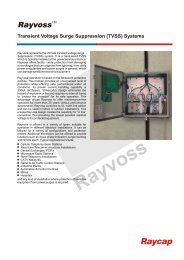
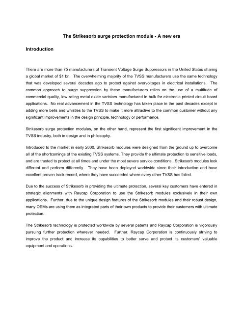
The <strong>Strikesorb</strong> surge protection module - A new eraIntroductionThere are more than 75 manufacturers of Transient Voltage Surge Suppressors in the United States sharinga global market of $1 bn. The overwhelming majority of the TVSS manufacturers use the same technologythat was developed several decades ago to protect against overvoltages in electrical installations. Thecommon approach to surge suppression by these manufacturers relies on the use of a multitude ofcommercial quality, low rating metal oxide varistors manufactured in bulk for electronic printed circuit boardapplications. No real advancement in the TVSS technology has taken place in the past decades except inadding more bells and whistles to the TVSS to make it more attractive to the common customer without anysignificant improvements in the design principle, technology or performance.<strong>Strikesorb</strong> surge protection modules, on the other hand, represent the first significant improvement in theTVSS industry, both in design and in philosophy.Introduced to the market in early 2000, <strong>Strikesorb</strong> modules were designed from the ground up to overcomeall of the shortcomings of the existing TVSS systems. They provide the ultimate protection to sensitive loads,and are trusted to protect at all times and under the most severe service conditions. <strong>Strikesorb</strong> modules lookdifferent and perform differently. They have been deployed worldwide since their introduction and haveexcellent proven track record, where they have succeeded where every other TVSS has failed.Due to the success of <strong>Strikesorb</strong> in providing the ultimate protection, several key customers have entered instrategic alignments with Raycap Corporation to use the <strong>Strikesorb</strong> modules exclusively in their ownapplications. Further, due to the unique design features of the <strong>Strikesorb</strong> modules and their robust design,many OEMs are using them as integrated parts of their own products to provide their customers with ultimateprotection.The <strong>Strikesorb</strong> technology is protected worldwide by several patents and Raycap Corporation is vigorouslypursuing further protection wherever needed. Further, Raycap Corporation is continuously striving toimprove the product and increase its capabilities to better serve and protect its customers’ valuableequipment and operations.
Problems with the current technology.1. Poor design and assumptions in design.It is common practice in the surge protection industry to connect protection devices in parallel in an effort toachieve higher ratings than just one device alone. It is also commonly assumed that the surge performanceof a number of devices is a simple multiplication of the performance of an individual device. This is not thecase both electrically (Standler (1)) and mechanically. Nobody assumes that by welding together ten familycars they obtain a truck even if it is possible to quote a total horsepower equal to a truck.Electrically it would be possible to match devices but this would need to be across the complete range ofoperation of the device and would therefore be prohibitively expensive. Even semiconductor devicesfabricated on the same wafer vary in performance due to minor defects and /or impurities in the lattice of thesemiconductor material.Poor mechanical design can lead to one individual device always having to handle more energy during anevent than its neighbors. As a rule an electrical transient takes the shortest, most conductive path and whenit goes around corners exerts forces on the current carrying conductors (Lorentz forces). The net result isthat for large transient currents, such as those produced by lightning, TVSS devices often explode as a resultof these forces and energies dissipated in one device rather than in all of the parallel connected devices.This is depicted in the following photograph.Photo 1:Exploded ModuleThere are several TVSS products that attempt to achieve equal path lengths for the devices connected inparallel. These products do lead to an increased resistance to transient events but tend to suffer from longerevents as the characteristics of the devices are affected by temperature and by no means do all the devicesin any of these designs have the same ability to dissipate energy as heat equally.2. Inadequate ratingFailure to identify the threat or its level correctly, if at all, often leads to a TVSS being applied for the wrongreason. There are many claims for protectors, such as speed of operation, that are pointless, not tested and
ultimately lead to the purchase of a unit on a “flavor of the month” basis. It is surprising to see how often lowrating fast blow fuses are used to protect the more exotic of the silicon diode arrestors. The argument usedto justify the fuse is that the transient is so fast that the fuse will not have time to operate. Operation of thefuse of course is basically that of getting sufficient I 2 t or energy into it to disrupt the link. It can be easilyshown that a typical 35A, fast blow fuse requires only 850A of a 100µs square impulse current to open. Fora 10µs square impulse the current required to open the fuse is 3000A.The energy contained in an 8/20µs lightning surge waveform is very similar to that in a 10µs square wave. Itis therefore clear that the claim of a 100kA protection capability for this device is unfounded. However, somecustomers believe in this type of protection, as it has no problems other than a fuse maintenance headache.Normally the strikes are not monitored in the field but are assumed to be large because the fuse opens. Thevery need to fuse a protector at this low level is an admission of failure by the manufacturer.3. Lack of testing or inappropriate testingVery few claims made by TVSS manufacturers are tested. Most manufacturers have only limited testequipment and laboratories. Testing is usually performed at around 10kA 8/20µs and the results quoted inthe range of multiple kA capabilities 50/100/200 or even greater than 1MA at best are wishful thinking, atworst are blind guesses. Some manufacturers quote external laboratory tests. One notable example of anindependent test program (Wiley (2)) found that only one of the TVSS units tested was capable of arepetitive high level surge. All the other units tested opened their fuse during the first impulse. The criterionused for the surviving TVSS was that there appeared to be no visible damage. This of course is little helpwhen trying to establish field performance and capability.Inappropriate testing is often performed or testing is misquoted. For example testing to UL 1449 is noindication at all that any useful transient suppression can be obtained. What UL 1449 does do is to indicatethat if the product is installed in exactly the same way the product has been tested then the risk of fire orexplosion has been minimized. No performance parameters are indicated other than the SVR which is onepoint on a graph a long way from the majority of transients. Conformance to UL 1449 does not mean thatfire and explosion will not take place only that it will be limited to the TVSS outer box. Often making holes inthe box to bring in cables can lead to the fire/smoke getting out of the box. Testing is most often rendereduseless by failing to test the actual protection provided to a load in a typical installation. Tests are done withshort cables and voltages measured at the protector and not at the load.4. FusingFusing takes two forms: overcurrent (this was explained earlier), and thermal in response to the fire failuresof earlier devices. It is certainly an indication of inadequate rating, however, fusing does lead to failure of theprotector for a number of reasons. Most obviously when a fuse opens the protector is rendered totallyineffective.
Thermal fuses are known to have reliability issues and age over a period of around five years usuallyaccentuated by thermal cycling. The technology used for thermal fuses in coffee pots, low melting pointmetals supported in wax, is used in some TVSS units. Experience with thermally cycled thermal fusesshows replacement periodically is needed to maintain normal operation. Other examples of thermal fusesare the low melting point solder held in tension by a spring. These devices had the problem that with agesolder cracking occurred and the devices opened for no other reason. The same technology in TVSS unitssuffers from the same conclusion, premature operation. It should be no surprise that this is a problem as it isknown that a soldered joint in tension will crack and lead to a “dry” joint. The cause is soft metal flowing andcracks propagating at the high stress areas.Conventional and Thermal fuses also suffer ageing from mechanical shock. Mechanical shock can becreated during operation of the TVSS by the transients. Martzloff (3) showed that fuses are progressivelyweakened by transient currents. In other words the reliability of the protector is reduced as a result ofincluding a device (fuse) that is present to protect the protector or present to protect the customer from theprotector.5. End of life Failure modeIt is well accepted by the electronics industry that the end of life mode for a series protection componentshould be open circuit. This refers of course to a fuse. The logic is that if the current into a piece ofequipment becomes too high the device operates interrupting the current to the device turning off thefunction of the device. In the telecom world gas discharge tubes have an end of life that is specified as amust and is referred to as “safe failure”. This requirement states that a gas tube should operate to a shortcircuit under certain conditions thereby rendering the equipment protected at all times and alerting theultimate failure of the protector by taking the service off line. This is also the case in the power world wherethe technique is referred to as “crowbaring the supply”. The failure mode of existing TVSS components hasbeen designed towards open circuit. In general a fuse is utilized to disconnect the device from the circuit,under adverse conditions. In other words there are conditions that require an over voltage protection deviceto be disconnected from the power supply, in order to prevent catastrophic failure of the protector. It seemsodd that the load, which is supposed to be protected by the TVSS is left to deal with the problem (faultcoming through the power source) without protection, simply because the protector “has managed to protectitself” by opening the fuse. The only other possible reason is that the TVSS is very weak and is likely to failthus making the use of a disconnect device, a requirement. This also assumes that the load is capable ofworking unprotected.Furthermore it can been shown that the very operation of a fuse causes raised transient voltages at the inputof the fuse and away from the SPD the fuse is protecting.A device that crowbars the supply may have high current circulating through it but the voltage across thedevice is reduced to a very small level. Although the device still fails it fails in a safe manner. Such a device
would need to be able to crowbar high prospective currents and safely open line fuses in the order of severalhundred amperes. Such a device would also need to improve vastly on the reliability of overcurrent devicesin order to avoid nuisance tripping of the line supply. To increase the reliability of this device its capacity todissipate energy from transients and swells should be significantly higher than that previously achieved byconventional TVSS devices.Installation instructions commonly use phrases like “keep the leads as short as possible”, and “use a largediameter wire” etc. Not one mentions the effect of lead inductance or the effect of inductance of any breakeror fuse used to connect to the power supply. There are two basic types of installation of a TVSS as shown inthe diagram below “T” and “In Line” or Kelvin connection.“T” ConnectionINLoad“In Line”, Kelvin ConnectionINLoadFigure 1:Connection methodsIn the “T” connection, the load is exposed to the sum of the voltage drop across the lead wires, the TVSSfuse and the clamping voltage of the Surge Protective Device (SPD), while in the Kelvin connection method,the load voltage is limited to the let-through voltage of the SPD irrespective of the length of the lead wire asshown in Figure 1. Consequently it is easy to conclude that the “T” connection is the least desirable sincethe Kelvin connection eliminates lead inductance completely. However, it requires major changes to thedesign of the TVSS device.6. FiresAs stated earlier the end of life failure of a varistor can be arcing and burning. Revisions of the UL 1449standard have attempted to put in place tests to look for abnormal failure modes of TVSS devices.Specifically a test was put in place under which, the voltage across a varistor is set at twice its nominaloperating level and is maintained at this level for 7 hours. The purpose of the test was to observe the failuremode of the TVSS and to check that no fire or smoke is generated as a result of this permanent overvoltage.The TVSS industry took this test and looked for a practical situation where this doubling of voltage could
occur and came up with the lifted neutral scenario. Several manufacturers have managed to pass therevised UL standard by taking a higher voltage device and labeling it as a lower voltage device, for examplea 240V device is labeled 120V. When the test is performed, the device conducts no current, dissipates noenergy and hence passes the test therefore, meeting the UL1449 2 nd edition requirements.An engineered remedyBased on the above discussion, we summarize in the following, the requirements for a reliable surgeprotector.a) The load should never be exposed to damaging transients/surges whatever the condition of theprotector.b) The protector should operate in such a way as to have no additional safety risks e.g. smoke, fire andexplosion.c) The reliability and lifetime of the protector is greater than the equipment/load being protected.d) Installation should not affect the ability of a protector to perform its intended function.e) The protector should be able to deal with all abnormal line conditions and provide protection at alltimes.These requirements translate into the following “desirable” protector features:i. No flammable material should be used in the protector i.e. no potting material.ii.iii.iv.The protector must be physically robust in order to sustain high amounts of energy withoutdisintegrating.The protector should require no additional fusing in order to meet the UL 1449 safety standard.The protector should have safe end of life, e.g. short circuit.v. The protector must be capable of installation using the “Kelvin” method. However, the protectorcould be installed in “T” configuration if desired.vi.vii.viii.The protector should have a long lifetime, ideally greater than 15 years in an exposed environment.The protector should be able to dissipate absorbed transient/surge energy safely without undueheating.The protector must have minimum internal dynamic resistance and minimum inductance.The <strong>Strikesorb</strong> surge protection module shown in the photograph below is designed to meet the aboverequirements.
Large Thermal Capacity ElectrodesStrong Aluminum Housing1500+ Pounds of PressureNo Fuel to BurnLow Dynamic Resistance& Low Residual VoltageSingle, Distribution-Grade Varistor– No Parallel MOVsFuseless OperationPhoto 2:<strong>Strikesorb</strong> Surge Protection Module<strong>Strikesorb</strong> Design FeaturesMechanical:The protector is housed in a robust, hermetically sealed metal casing. There is no flammable material usedin the protector. The varistor disk is ether 80mm in diameter (<strong>Strikesorb</strong> 80 models) or 40mm in diameter(<strong>Strikesorb</strong> 40 models) and is placed between two electrodes that have high thermal capacity andconductivity. The disk is not rigidly constrained but held under a high pressure to overcome the Piezoelectricand Lorentz forces, occurring during a transient and allow for thermal expansion. Heat generated in thevaristor disk is efficiently dissipated to the environment via the electrodes and the device casing to theconnected bus bars/metalwork. The high thermal conductivity of the materials used ensures that anytemperature rise of the varistor is kept to a minimum. Some polyurethane resin potted protectors claim tohave heat dissipation capabilities but are severely limited by the thermal conductivity of the filled resin whichis more than three decades lower than the material used here. In comparison, <strong>Strikesorb</strong> has the ability toremove from the varistor wafer 1000 times more thermal energy than conventional TVSS devices. Thisleads to less temperature rise in the device and hence a much longer extended lifetime. The thermal heatsinking effect of the electrodes also serves to smooth out any heat gradients across the surface of thevaristor, caused by minor imperfections in the amorphous crystalic MOV material, thus preventing thermalrunaway.
Electrical:<strong>Strikesorb</strong> is designed to have minimum inductance connections while at the same time maximizing thecapacitance of the varistor disk. Its design is characterized by coaxial symmetry. This results in a devicewith minimum impedance and hence minimum response time. The thickness of the electrodes also plays asignificant role in ensuring the current through the varistor is planar/parallel (uniform) and no current‘hogging’ occurs. In conventional varistors using thin wire leads and thinner electrodes, current paths are byno means parallel and current ‘hogging’ occurs leading to reduced device surge capacity, hot spots andultimately failure under surge conditions. Figure 2 illustrates this point.Conventional varistor section unevencurrent<strong>Strikesorb</strong> varistor withparallel current paths.Figure 2:Current distribution in conventional varistors and in the <strong>Strikesorb</strong> module design.As there is insufficient electrode material, current cannot evenly spread out in the varistor disk and currenthogging occurs. It can also be seen that the path lengths for individual current filaments vary considerably,which leads to the following three effects:i. The resistance of the paths towards the outer edge of the device is higher and hence less currentflows there.ii.The transit time of the current traveling through the longer paths is higher.The consequence is that the capacity of the device is reduced below the expected material capability andthat the current density is increased due to the use of less than the total volume of the varistor which resultsin higher clamping voltage and the development of preferential paths and ultimately to failure.The <strong>Strikesorb</strong> device overcomes this by making all path lengths essentially equal and allowing sufficientlyhigh conductivity material to produce parallel current flow in the varistor slice. This leads to a device thatutilizes all varistor material equally at all frequencies.
The following table summarizes the features and benefits of the <strong>Strikesorb</strong> module design:<strong>Strikesorb</strong> FeaturesStrong metallic housingOne varistor designDistribution grade varistorsLarge metallic flatelectrodesVaristor under springcompressionNo fuseCylindrical symmetricaldesign with large.Large connection leadsEnvironmentally SealedPatentedLong LifeTested PerformanceUL RecognizedWarrantyBenefitsDoes not catch on fire, smoke or explode – Efficient heat managementand removal of surge energy from the varistor which leads to a longerservice life High Energy handling capabilityDoes not rely on equal current sharing between multiple smaller ratingMOVs - Eliminates disadvantages of conventional designsLarger MOV - Better quality material - Homogenous wafer - Can handlehigher energy surgesEnsure better contact – lower contact resistance – Efficient cooling ofvaristor and maximum use of the full surface area of the varistorForces do not crush the varistor – Ensures good contact and lowerresistance at electrode interfaces resulting in lower clamping voltages –Ensures a short (fail safe) end of life modeLower clamping voltages - Enables in-line installation - Protection stayson line if connected in-line - No maintenance required.Reduces the inductance of the module – Reduces the let throughvoltage – Increases the mechanical strength of the connection leads –Ensures the fastest possible response time – Avoids the majority of theLorentz forces since the surge current does not go around corners.Enables the <strong>Strikesorb</strong> module to be installed in a circuit capable ofdelivering up to 200kA and operate in short to open a Class J, T, R, H,or K fuse. <strong>Strikesorb</strong> modules have been tested behind 400A,Square D, LA frame with 42kA available short circuit current.Can be installed anywhere without affecting performance – Varistor isnot potted in a polymeric material that is combustible and can causesmoke and act as a fuel for fire.World wide protectionUnder normal conditions life expectance is 20 yearsSpecifications are backed by measurements in in-house as well asoutside independent reputable test laboratories – Tested according tospecifications of secondary surge arrester which are more stringentthan those of the TVSSEnables installation outside of the TVSS box in OEM integratedapplications.Backed by a solid 10 year replacement warrantyElectrical verification testingGiven the practice in the industry i.e. making unfounded claims and estimates of performance, it was decidedat an early stage to perform electrical tests that could verify the performance of the <strong>Strikesorb</strong> modules.Generally, the tests were performed according to known and broadly accepted international standards likethe IEEE-C62, the IEC-61643, VDE-675, UL-1449 2 nd edition and NEMA-LS1. Often the test parameters
were made more onerous than those required by the standards to show the exceptional capabilities of the<strong>Strikesorb</strong> modules.The following table summarizes the performance capabilities of both <strong>Strikesorb</strong> modules.Performanceparameter<strong>Strikesorb</strong>-80Strieksorb-40Energy handling: 250 x 1000A @ 2000µs (2500J/impulse) 250 x 500A @ 2000µs(1250J/impulse)High current impulses:200kA - 8/20µs100 x 65kA – 8/20µs2000 x 10kA – 8/20µs25kA – 10/350µs140kA - 8/20µs2000 x 10kA – 8/20µsAccelerated aging: 1000 hrs @ 115ºC & MCOV 1000 hrs @ 115ºC & MCOVDynamic resistance: < 5mΩ < 5mΩAbnormal overvoltagetest (UL-1449):Upstream overcurrent protection of1200A (100kA IR) and 800A (200kA IR)Upstream overcurrent protectionof 400A (100kA IR)Figure 3 shows a comparison between the let-through voltage of the <strong>Strikesorb</strong> 40-120 and an equivalentcompetetive device based on multiple varistor technology under conditions of 8/20µs lightning current.Let through Voltage at intremediate surge currents1200.01000.0Voltage (V)800.0600.0400.0200.00.010 30 50 60Surge current at 8/20µs (kA)<strong>Strikesorb</strong> 40-120Parallel MOVFigure 3:Let-through voltage/current characteristics.It is intersting to see that at 10kA both protectors perform essentially the same. As the surge current level isincreased the effect of the lead inductance of the small MOVs starts to show more and more and is reflectedas an increase of the let-through voltage. That is assuming of course that the protective fuse does not openand render the whole comparison meaningless.
Field experienceLaboratory tests are essential to provide a good indication for the capabilities of the protector undersomewhat sterilized conditions. One must not forget that all lab tests are designed in a way to provide ameans to compare the performance of different products when tested at different times and locations.However, the real measure of a successful technology, is its performance in the field. No claims is worthmuch unless it translates into better protection of the customer equipment.<strong>Strikesorb</strong> modules were intially deployed in environments with the worst power quality, worst lightning andthe worst history of protector failure that could be found to prove their exceptional performance. Thisstrategy resulted in a significant number of units being located across South America, Southeast Asia andparticular locations in North America and Europe. As a result of the success in the field, deploymentcontinued on a wide scale and to date more than 120,000 protectors are installed worldwide.Examples of success stories are plentiful. One site in particular had a very low mean time to failure, and along mean time to repair (3 days). The site, a mountain top telephone relay site in South America, hadsuffered several TVSS fires and explosions. Various manufacturers of TVSS had been tried always withTVSS failures and usually accompanied with equipment failure and service loss. The longest lasting TVSSbefore Srikesorb (Rayvoss unit was installed) on this site had been 10 days (in the lightning season). TheRayvoss unit installed on this site has been in service for 4 years without any interruption. The onlyengineering work performed to install the Rayvoss system was to arrange for a “Kelvin” type connection at200A per phase.Another more recent example is the case of a surface coal mine in Europe where they had major trouble withPLCs contolling convayor belts being damaged due to surges produced by lightning as well as switchingoperations. Those failures resulted in a huge operational cost due to the intrruption of production. Rayvosswas installed at the mine as part of a field trial, since the owners had bad experience with several otherTVSS systems. As Rayvoss proved to solve the problem the management of the mine decided to protect thewhole mine with Ravoss units. The payback period for their investment was less than one year! Figure 4shows the results of the study performed on-site before and after the installation of the Rayvoss unit.
Figure 4:Power line transient overvoltages in a conveyor belt PLC measured in a 24h period beforeand after installing Rayvoss.Due to its unique design features and its exceptional field performance, the <strong>Strikesorb</strong>/Rayvoss productshave been adopted by several large organizations in their applications. Customers like the FAA, CingularWireless, Schlumberger, Bell Canada, Telus, US Navy, Telefonica, Raytheon, and Telmex are just a fewexamples. Further, Toshiba USA and ASCO are two of those OEMs who adopted the technology in theirown applications.ConclusionUnderstanding the root causes of conventional protector failures has led to a new generation of TVSSdevices based on a completely new concept - <strong>Strikesorb</strong>. During the last 5 years, this technology has beendeployed in a large variety of applications worldwide, with remarkable success. More information on<strong>Strikesorb</strong> and Rayvoss TVSS products is available at http://www.rayvoss.comReferences1) Standler Dr RB, Protection of Electronic Circuits from Over voltages ISBN 0-471-61121-22) Wiley P., November 1999 Power Quality.3) Martzloff F.D., 1985, Matching Surge Protective Devices to Their Environment, IEEE Transactions