Circuit Breakers Timing Test System - Measurement Science Review
Circuit Breakers Timing Test System - Measurement Science Review
Circuit Breakers Timing Test System - Measurement Science Review

Create successful ePaper yourself
Turn your PDF publications into a flip-book with our unique Google optimized e-Paper software.
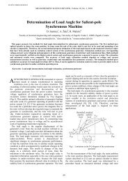
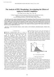
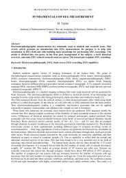
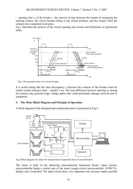
MEASUREMENT SCIENCE REVIEW, Volume 7, Section 3, No. 5, 2007- opening time t o of the breaker -. the interval of time between the instant of energizing theopening release, the circuit breaker being in the closed position, and the instant when thecontacts have separated in all poles.Fig.1 illustrates the process of the switch opening and closure and definitions of operationaltimes.coil currentAPosition Xof movingcontactsmm150100500t msOpen position(Final resting position)closingL3 openingLL LL 21 1 L23contact separationcontact closureclosed position(Final resting position)tdtdtofor L2 tcfor L3Opening pulseClosing pulset msFig.1 The operation times of a circuit-breakerIt is worth noting that the time discrepancy t d between the contacts of the breaker must bewithin certain tolerance limit – usually 5 ms. The time difference between opening or closingall contacts may generate huge voltage spikes that could potentially damage network and itsequipment.3. The Meter Block Diagram and Principle of OperationA block diagram of the designed and constructed meter is presented in Fig.2.controlcircuit+VInput circuit50 VDisplayFD1D2+ VMicrocontrollerRS 232circuit-breakerKeyboardFig.2 Block diagram of a meter for measurement of operation times of circuit breakerThe meter is built of the following interconnected functional blocks: input circuits,microcontroller being a central unit of the meter (single-circuit microcontroller AT89C51),display and a keyboard. The input circuit plays very important role, because makes possible56