To download the DC16 user manual, click here! - Coastal Business ...
To download the DC16 user manual, click here! - Coastal Business ...
To download the DC16 user manual, click here! - Coastal Business ...
You also want an ePaper? Increase the reach of your titles
YUMPU automatically turns print PDFs into web optimized ePapers that Google loves.
Setting TimeFrom <strong>the</strong> normal operating mode, simplyuse <strong>the</strong> Arrow Keys ONLY to set <strong>the</strong>time. Do not touch <strong>the</strong> PRG key.Hold down ei<strong>the</strong>r <strong>the</strong> Up or Down arrowkey for more than 2 seconds and <strong>the</strong> timewill increase rapidly.Press BOTH Arrow Keys and <strong>the</strong> timewill reset to 00 seconds.Pre-Press TimerT<strong>here</strong> is a second timer available foruse, called <strong>the</strong> “Pre-Press Timer”.This feature is useful if a multiple-stepprocess is performed.For example: If a product must bepre-pressed for 5 seconds before amain pressing cycle of 20 seconds, <strong>the</strong>Prepress timer can be set for 5 secs, and<strong>the</strong> main timer for 20. When <strong>the</strong> operator closes <strong>the</strong> press, <strong>the</strong> 5-sectime counts down. When <strong>the</strong> operator opens <strong>the</strong> press, <strong>the</strong> time settingswitches to 20 seconds.The word PREPRESS will be displayed next to <strong>the</strong> pre-press time settingwhen it is active. <strong>To</strong> set <strong>the</strong> pre-press time, simply use <strong>the</strong> Arrow Keysto set <strong>the</strong> time. If PREPRESS is not displayed next to <strong>the</strong> time, quicklyclose and <strong>the</strong>n open <strong>the</strong> press to switch to <strong>the</strong> prepress time.<strong>To</strong> turn ON <strong>the</strong> prepress timer feature, enter <strong>the</strong> User Options Menus(see page 18) and go to <strong>the</strong> PPR setting and turn it ON. (see page 22)6
Setting PressurePressure is set <strong>manual</strong>ly using <strong>the</strong> large black Pressure AdjustmentKnob. T<strong>here</strong> is one important rule of thumb when setting pressure: Thepress MUST LOCK IN PLACE when lowering and clamping <strong>the</strong> press.Do not simply let <strong>the</strong> platen rest on <strong>the</strong> pad. A good solid two-handedlocking force is recommended when first doing transfers to insure goodresults. A “Ka-Thunk” <strong>click</strong>/clamp sound will result when locking <strong>the</strong>press in place.• <strong>To</strong> decrease <strong>the</strong> pressure, turn <strong>the</strong>pressure knob to <strong>the</strong> left, counterclockwise.The top head will rise away from <strong>the</strong> lowertable.• <strong>To</strong> increase <strong>the</strong> pressure, turn <strong>the</strong>pressure knob to <strong>the</strong> right, clockwise. Thetop head will lower toward <strong>the</strong> pressing table.Digital Pressure Bar GraphThe Digital Pressure BarGraph indicates a basic 0-9scale of pressure exerted.The pressure bar graphresets when <strong>the</strong> press isclosed/locked while timing.If <strong>the</strong> pressure adjustment has been changed, or a different thicknessitem has been placed in <strong>the</strong> press, <strong>the</strong> pressure bar graph will not changeuntil <strong>the</strong> press is closed and locked and <strong>the</strong> timer is counting.This bar graph is directly related to <strong>the</strong> amount of pressure, or resistance,being felt and applied to <strong>the</strong> bottom table. If a thicker item is placed in<strong>the</strong> press, and no adjustments are made to <strong>the</strong> pressure knob, <strong>the</strong>n <strong>the</strong>amount of pressure clamping down will be greater, and <strong>the</strong> bar graphwill show a higher number. Here are some bar graph guidelines:A very light pressure slight clamping would be in <strong>the</strong> 0 to 3 range.A good medium pressure for most applications would be 4 to 6.Excessively high pressure for demanding items would be 7-9.7
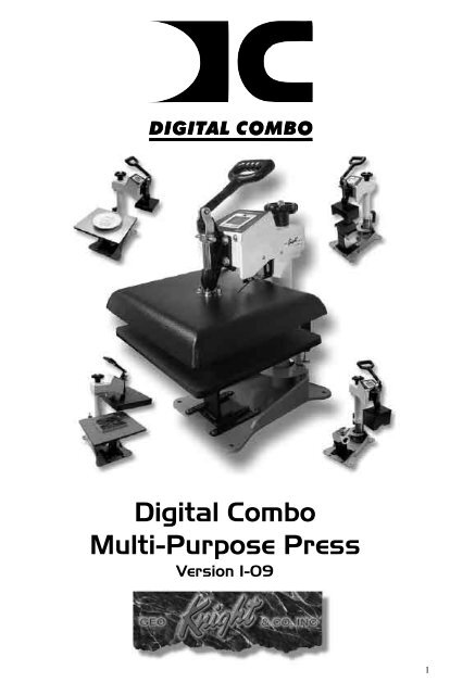
Using AttachmentsThe main feature that makes <strong>the</strong> Digital Combo so versatile is <strong>the</strong>interchangeability of <strong>the</strong> heat platens. Because <strong>the</strong> heat platens aremodular in <strong>the</strong>ir method of connection, one platen can be unpluggedand ano<strong>the</strong>r attached, in its place. These platens are “Hot Swappable”.You do not need to wait for <strong>the</strong> platens to cool off to remove.The following instructions apply to <strong>the</strong> 14x16, 12x14, cap, plate & mugheat platen attachments. All of <strong>the</strong>m disconnect and connect in <strong>the</strong> samemanner.Removing a Heat PlatenThe heat platen can be safely disconnected with<strong>the</strong> machine on. However, <strong>the</strong>rmal gloves oroven mitts must be used when handling hot heatplatens.• Unplug <strong>the</strong> modular connector. This is doneby unscrewing <strong>the</strong> safety lock and pulling <strong>the</strong>connectors apart.• Lower <strong>the</strong> heat platen so it rests on <strong>the</strong> bottomtable, and do not clamp it.• Pull out <strong>the</strong> quick release pin from <strong>the</strong> linkage.It is easiest to remove when <strong>the</strong>re is no pressureon <strong>the</strong> side links or on <strong>the</strong> heat platen shaft.• Once <strong>the</strong> quick release pin is removed, lift <strong>the</strong>handle away, exposing <strong>the</strong> heat platen shaft nowdisconnected from <strong>the</strong> linkage.• Lift up on <strong>the</strong> heat platen slightly, enough to swingit out away from <strong>the</strong> bottom table. Lower <strong>the</strong> heatplaten down and out of <strong>the</strong> clamp linkage.10
Attaching a heat platenThe heat platen can be safely connected with <strong>the</strong> machine on. However,<strong>the</strong>rmal gloves or oven mitts must be used when handling hot heatplatens.• Lift <strong>the</strong> heat platen into <strong>the</strong> clamp linkage. Makesure <strong>the</strong> rear guide fork holds onto <strong>the</strong> guide pinin <strong>the</strong> back post of <strong>the</strong> frame. This holds <strong>the</strong> heatplaten in a straight position and keeps it fromrotating.• Reattach <strong>the</strong> quick release pin through <strong>the</strong> linkageand <strong>the</strong> heat platen shaft.• Reconnect <strong>the</strong> modular connector. An Err displaymight read on <strong>the</strong> controller if in <strong>the</strong> Normaloperating mode. If it does not read a temperatureafter <strong>the</strong> heat platen is reconnected, turn <strong>the</strong>machine off and <strong>the</strong>n on again.11
Cap Hold-down Device (For Cap Attachment Only)T<strong>here</strong> is a curved 1/2-moon capholddown device for stretching <strong>the</strong>cap over <strong>the</strong> curved bottom table.Simply pull <strong>the</strong> back strap of <strong>the</strong>cap behind <strong>the</strong> pedestal and under<strong>the</strong> 1/2-moon shaped bracket. Thiswill hold <strong>the</strong> cap in place for properprinting.Aligning <strong>the</strong> PedestalThe table can be easily adjusted in a straight position if <strong>the</strong> heat platendoes not correctly line up with <strong>the</strong> pressing surface. The pedestal <strong>the</strong>table rests on can slide front to back on <strong>the</strong> base of <strong>the</strong> machine. Loosen<strong>the</strong> screw in <strong>the</strong> gibb plates that holds <strong>the</strong> pedestal in place in order toadjust its position.The pedestal can also be slightly rotated in order to align with <strong>the</strong> upperplaten. Loosen all (4) screws holding <strong>the</strong> gibb plates in place, position/rotate <strong>the</strong> pedestal to <strong>the</strong> desired place, and retighten <strong>the</strong> gibb plates.Optional Forms / Custom PedestalsThe standard tables included with <strong>the</strong> DK7or DK8 will accommodate most items.However <strong>the</strong>re are o<strong>the</strong>r sized bottomtables that are instantly interchangeable.For <strong>the</strong> DK7, <strong>the</strong>re are 3 different curvedforms (<strong>the</strong> top heat platen stays <strong>the</strong> same).The mid-sized and youth-sized formsare not included with <strong>the</strong> press. The midsized“EURO” form is especially usefulfor solving wrinkling of caps in <strong>the</strong> middlearea for lower-profile tight-fit caps.Custom pedestals, bottom tables, and o<strong>the</strong>rcustom solutions are also available from <strong>the</strong> factory.12
How to use <strong>the</strong> Cap AttachmentThe cap attachment works <strong>the</strong> same as acap press. The only difference is that <strong>the</strong>swing-away style Digital Combo pressallows complete access to <strong>the</strong> cap when<strong>the</strong> heat platen is swung out, as opposed totypical stand-alone clamshell cap presses.Here are some tips for using <strong>the</strong> capattachment:Make sure <strong>the</strong> cap holddown device isattached to <strong>the</strong> bottom pedestal.Make sure <strong>the</strong> proper bottom form is used.If wrinkling/folding of <strong>the</strong> middle of <strong>the</strong>cap occurs, this is a good indication that<strong>the</strong> wrong form is being used.Make sure <strong>the</strong> lower pedestal is adjusted and slid forward or backwardto line up with <strong>the</strong> heat platen above.How to use <strong>the</strong> Mug AttachmentThe mug attachment will print one half sideof <strong>the</strong> mug in one pressing cycle. Here aresome tips for using <strong>the</strong> mug attachment:Use <strong>the</strong> Additional 1/8” Green Square Padfor smaller 11 oz mugs. Lay <strong>the</strong> pad on topof <strong>the</strong> transfer paper, <strong>the</strong>n press.Wider “steins” and 15oz mugs do not use<strong>the</strong> extra pad. The heater is sized for largerdiameter mugs.Sublimation transfers can be left on <strong>the</strong>mug, and <strong>the</strong> mug can be flipped andpressed on <strong>the</strong> opposite side for a continuous full wrap-around print.13
How to use <strong>the</strong> Plate AttachmentThe plate attachment allows<strong>the</strong> operator to press downinside a dish or o<strong>the</strong>r indentedobject. Here are some tips forusing <strong>the</strong> plate attachment:Use <strong>the</strong> large T-Shirt flatbottom table.Place <strong>the</strong> 3-sided aluminumtray on top of <strong>the</strong> T-Shirttable. This will protect <strong>the</strong>main T-Shirt silicone padfrom being cut into by <strong>the</strong>plate’s bottom edges.Plate <strong>the</strong> black circular silicone pad on <strong>the</strong> tray. Center <strong>the</strong> pad so thatit is directly underneath <strong>the</strong> plate heater block attachment when swungover. Make sure it lines up directly under <strong>the</strong> plate heat platen. Thenpeel <strong>the</strong> backing off <strong>the</strong> circular black silicone pad and permanentlystick it to <strong>the</strong> tray.The purpose of <strong>the</strong> black circular pad is to automatically center <strong>the</strong> plateunder <strong>the</strong> heat platen. It also provides cushioning when pressing plates.Set <strong>the</strong> clamping pressure of <strong>the</strong> press so <strong>the</strong> black pad is compressed to50% its height. Pressing heavier may risk breaking certain fragile styleplates.Lay <strong>the</strong> 1/8” green circular pad on top of <strong>the</strong> transfer paper in <strong>the</strong> plate.Pressing Ceramic Tile<strong>To</strong> press ceramic tile, use <strong>the</strong> standard T-Shirt heat platen and bottomtable. Lay <strong>the</strong> 1/2” White Nomex Felt padding on top of <strong>the</strong> blacksilicone pad. Then lay <strong>the</strong> transfer paper face-up, and <strong>the</strong> tile face-downinto <strong>the</strong> image. Press <strong>the</strong> tile from <strong>the</strong> back side, firmly. This wraps <strong>the</strong>transfer paper nicely around <strong>the</strong> radius of <strong>the</strong> tile.14
Programmable PresetsHow Presets WorkT<strong>here</strong> are 70 programmable presets in <strong>the</strong> controller. The operator canstore a Temperature, Time, Prepress Time, and Pressure setting in eachpreset.When a preset program is loaded by <strong>the</strong> operator, <strong>the</strong> Current TemperatureSetting, Time and Prepress Settings (if <strong>the</strong>re is a Prepress setting in thatpreset) are updated in <strong>the</strong> normal operating mode.The pressure is NOT set for <strong>the</strong> operator mechanically. A brief displayof <strong>the</strong> pressure value in <strong>the</strong> preset is shown while updating <strong>the</strong> currentsettings. This is simply a reference... a reminder of what pressure setting<strong>the</strong> operator must adjust for that preset.T<strong>here</strong> are 2 main functions to using <strong>the</strong> presets. LOADING and EDITING<strong>the</strong> preset. LOADING a preset simply means selecting a desired preset,and returning to <strong>the</strong> normal operating mode w<strong>here</strong> <strong>the</strong> current settingsare changed. EDITING a preset is when <strong>the</strong> operator actually changes<strong>the</strong> preset’s settings.Loading a Preset<strong>To</strong> enter <strong>the</strong> presets, press <strong>the</strong> PRGkey.SET will display on <strong>the</strong> screen.Use <strong>the</strong> Arrow Keys to select a presetfrom 00 to 70.Press PRG to return to <strong>the</strong> normaloperating mode. The current active Temperature, Time & Prepress timesettings (if <strong>the</strong>re is a prepress setting in that preset) are now updatedwith <strong>the</strong> presets values.15
Editing/Programming a Preset<strong>To</strong> edit a preset and change it’s values to yourown desired settings, you simply use <strong>the</strong> TEMPkey while in <strong>the</strong> SET preset mode.From <strong>the</strong> normal operating mode, press <strong>the</strong> PRGkey. SET displays on <strong>the</strong> screen. Use <strong>the</strong> ArrowKeys to select <strong>the</strong> preset # you wish to edit.Press <strong>the</strong> TEMP key. The temperature will flash.Use <strong>the</strong> Arrow Keys to set <strong>the</strong> temperature forthat preset.Press <strong>the</strong> TEMP key. The time will flash. Use<strong>the</strong> Arrow Keys to set <strong>the</strong> time for that preset.Press <strong>the</strong> TEMP key. The Prepress time willflash. Use <strong>the</strong> Arrow Keys to set <strong>the</strong> Prepresstime. Set <strong>the</strong> Prepress time to 00 if only one timeris to be used for that preset. Setting Prepress to00 will disable <strong>the</strong> Prepress feature.Press <strong>the</strong> TEMP key. The Pressure referencevalue will flash. Use <strong>the</strong> Arrow Keys to set <strong>the</strong>pressure for that preset. This will display 0 to 9for presses configured for Bar Graph Pressurereadout, and will display 0:00 to 10:00 forpresses configured for a Height Gauge readout.Press <strong>the</strong> TEMP key. The screen returns to <strong>the</strong>preset #. Press PRG to return to <strong>the</strong> normaloperating mode, or use <strong>the</strong> Arrow Keys to selecta different preset and edit that as well.16
A Walkthrough Tutorial for using PresetsHere is a tutorial of programming 2 different presets, and <strong>the</strong>n anexample of using <strong>the</strong>m in normal daily operations. Do this walkthroughto practice using presets.Part 1: Programming 2 different presets.From <strong>the</strong> normal operating mode, press PRG. SET appears.Use <strong>the</strong> arrow keys to select SET 01.Press TEMP. Set <strong>the</strong> flashing temperature to 400 with <strong>the</strong> arrow keys.Press TEMP. Set <strong>the</strong> flashing time to 45 with <strong>the</strong> arrow keys.Press TEMP. Set <strong>the</strong> flashing Prepress time to 00 with <strong>the</strong> arrow keys.Press TEMP. Set <strong>the</strong> flashing Pressure ref to 6 with <strong>the</strong> arrow keys.Press TEMP. Use <strong>the</strong> arrow keys to select SET 02.Press TEMP. Set <strong>the</strong> flashing temperature to 350 with <strong>the</strong> arrow keys.Press TEMP. Set <strong>the</strong> flashing time to 12 with <strong>the</strong> arrow keys.Press TEMP. Set <strong>the</strong> flashing Prepress time to 3 with <strong>the</strong> arrow keys.Press TEMP. Set <strong>the</strong> flashing Pressure ref to 8 with <strong>the</strong> arrow keys.Press TEMP. Press PRG to leave <strong>the</strong> preset mode.Presets SET 01 and SET 02 have now been programmed.Part 2: Loading <strong>the</strong> presets. Let’s say we are powering on <strong>the</strong> machineand starting a job. The first job will need to use preset 01, and later on<strong>the</strong> next job will need preset 02.From <strong>the</strong> normal operating mode, press PRG. SET appears.Use <strong>the</strong> arrow keys to select SET 01 <strong>the</strong>n Press PRG. Done!The press is now set for 400°F and 45 seconds and will start to heat tothat temperature. When leaving <strong>the</strong> presets, <strong>the</strong> screen briefly displayedPRS 6 - indicating you must <strong>manual</strong>ly set <strong>the</strong> clamping pressure so <strong>the</strong>bar graph shows 6 (or close to it) at <strong>the</strong> bottom of <strong>the</strong> screen.Now let’s change to <strong>the</strong> next job. Press PRG. SET appears.Use <strong>the</strong> arrow keys to select SET 02 <strong>the</strong>n Press PRG. Done!The press is now set for 350°F, 12 secs, 3 prepress, and you are remindedto set <strong>the</strong> pressure heavier to 8 on <strong>the</strong> bar graph display (when closed).That’s it! You can load a preset as often as needed: just press PRG, pick<strong>the</strong> preset you want with <strong>the</strong> Arrow Keys, and press PRG again.17
User MenusEntering <strong>the</strong> <strong>user</strong> menus & optionsT<strong>here</strong> are many useful features beyond simply setting time & temperature,and storing presets. All of <strong>the</strong>se additional features are available to <strong>the</strong>operator in <strong>the</strong> User Menus.<strong>To</strong> access <strong>the</strong> <strong>user</strong> menus, simply press TEMP & PRG at <strong>the</strong> sametime from <strong>the</strong> normal operating mode and let go.(Try to use two hands and press <strong>the</strong> keys at <strong>the</strong> exact same time. If onekey is pressed too early from <strong>the</strong> o<strong>the</strong>r, <strong>the</strong> temperature setting or presetmodes may be activated instead. Turn <strong>the</strong> press off and <strong>the</strong>n on and tryagain.)Fahrenheit / CelsiusThe current and set temperature can bedisplayed in °F or °C. After entering <strong>the</strong><strong>user</strong> menus (see above), use <strong>the</strong> arrowkeys to select F or C. Press PRG to moveto <strong>the</strong> next menu item.Timer Counter UnitsThe timer and Prepress timer can be setfor mins/secs (default) or hours/mins. Ifspecial applications need a higher timerrange than 99 mins, 59 secs, this can bechanged. After entering <strong>the</strong> <strong>user</strong> menus(see top of page), Press PRG until CNTdisplays. Use <strong>the</strong> arrow keys to selectSEC or HR. Press PRG to move to <strong>the</strong>next menu item.18
Recorded Pressings (User Odometer)T<strong>here</strong> is an “odometer” that recordspressing cycles done. This can be clearedand reset to 0 at any time when needed.The figure scrolls and it’s beginning andend are separated by a “-” sign.After entering <strong>the</strong> <strong>user</strong> menus (seetop of page 18), Press PRG until RECdisplays. Use <strong>the</strong> arrow keys to reset <strong>the</strong>counter to 0. Press PRG to move to <strong>the</strong>next menu item.Pressure Minimum<strong>To</strong> reset and redefine “0” for <strong>the</strong> pressurebar graph, use this calibration menu. DoNOT adjust this setting unless you aresure adjustments are necessary.Adjust <strong>the</strong> pressure of <strong>the</strong> machine so<strong>the</strong>re is barely any locking pressurewhen clamping and locking <strong>the</strong> press.Press ei<strong>the</strong>r Arrow Key. The press nowconsiders this pressure as “0” on <strong>the</strong>Pressure Bar Graph Display.Press PRG to move to <strong>the</strong> next menu item.19
Pressure Maximum<strong>To</strong> reset and redefine “9” for <strong>the</strong> pressurebar graph, use this calibration menu. DoNOT adjust this setting unless you aresure adjustments are necessary.Adjust <strong>the</strong> pressure of <strong>the</strong> machineso <strong>the</strong>re is extremely heavy pressurewhen clamping and locking <strong>the</strong> press.Press ei<strong>the</strong>r Arrow Key. The press nowconsiders this pressure as “9” on <strong>the</strong>Pressure Bar Graph Display.Press PRG to move to <strong>the</strong> next menu item.Temperature Drop SenseThe press can be set to alarm if <strong>the</strong>temperature drops a certain range below<strong>the</strong> set temperature. This is useful towarn <strong>the</strong> operator if <strong>the</strong> press is toofar out of temperature range duringexcessive use.After entering <strong>the</strong> <strong>user</strong> menus (see top ofpage 18), Press PRG until DRP displays.Use <strong>the</strong> arrow keys to set it to OFF (default), or 10, 20, 30, etc.If <strong>the</strong> current temperature drops below <strong>the</strong> set temperature by that manydegrees, and alarm will sound. Press TEMP to silence <strong>the</strong> alarm.Press PRG to move to <strong>the</strong> next menu item.20
Keypad BeeperThe keypad beep can be silenced ifneeded. After entering <strong>the</strong> <strong>user</strong> menus(see top of page 18), Press PRG untilBEP displays. Use <strong>the</strong> arrow keys to setit to ON or OFF.Press PRG to move to <strong>the</strong> next menuitem.AlarmsThe timer alarm can be adjusted fordifferent beeping patterns. This candifferentiate between multiple presses,and allow <strong>the</strong> operator to have a shortbeep or a continuously repeating beep.After entering <strong>the</strong> <strong>user</strong> menus (seetop of page 18), Press PRG until ALRdisplays. Use <strong>the</strong> arrow keys to set it toOFF, or 1 through 10.Press PRG to move to <strong>the</strong> next menu item.• denotes a short beep._ denotes a longer beep.~ denotes infinite loop.Alarm # Alarm PatternOffNo alarm01 • • • _02 • • • _ ~03 • • _04 • • _ ~05 • • •06 • • • ~07 _ ~08 _09 •10 • (shorter)21
Finished Warning BeepThe press can sound a beep on <strong>the</strong> last3 seconds of <strong>the</strong> timer or Prepress timercountdown. This is useful if <strong>the</strong> pressis automatic and <strong>the</strong> operator needs awarning that <strong>the</strong> press is about to finish,open, or pop-up dramatically.After entering <strong>the</strong> <strong>user</strong> menus (see topof page 18), Press PRG until FWBdisplays. Use <strong>the</strong> arrow keys to set it toON or OFF.Press PRG to move to <strong>the</strong> next menu item.Prepress TimerThe press can cycle back and forthbetween two distinct timer settings:<strong>the</strong> normal countdown timer, and a 2ndPrepress timer. (see page 6). This menuitem turns <strong>the</strong> Prepress timer ON orOFF.After entering <strong>the</strong> <strong>user</strong> menus (see top ofpage 18), Press PRG until PPR displays.Use <strong>the</strong> arrow keys to set it to ON orOFF.If PPR is set to OFF, pressing PRG will return to <strong>the</strong> normal operatingmode.If PPR is set to ON, pressing PRG will move to <strong>the</strong> next menu item.22
Prepress AlarmsThe Prepress timer alarm can beadjusted for different beeping patterns.This allows for differentiating from <strong>the</strong>normal timer, and can allow <strong>the</strong> operatorto have a short beep or a continuouslyrepeating beep.After entering <strong>the</strong> <strong>user</strong> menus (see top ofpage 18), Press PRG until AL2 displays.The PPR menu must be set to ON for this menu to be visible. Use <strong>the</strong>arrow keys to set AL2 to OFF, or 1 through 10.Press PRG to move to <strong>the</strong> next menu item.• denotes a short beep._ denotes a longer beep.~ denotes infinite loop.Alarm # Alarm PatternOffNo alarm01 • • • _02 • • • _ ~03 • • _04 • • _ ~05 • • •06 • • • ~07 _ ~08 _09 •10 • (shorter)Operator LockoutAn operator lockout feature is availableto <strong>the</strong> owner of <strong>the</strong> press. This prevents<strong>the</strong> average <strong>user</strong> from changing anysettings or adjusting anything on <strong>the</strong>controller.Contact <strong>the</strong> factory for instructions onusing this feature.23
Parts / Maintenance / MiscInterchangeable TablesThe lower table on <strong>the</strong> machine is interchangeable. Different sizedoptional tables can be obtained for various materials & handlingrequirements.The tables simply fit right onto <strong>the</strong>bottom pedestal. T<strong>here</strong> are two steelpins that look like “bullets” that fitinto <strong>the</strong> two corresponding holesin <strong>the</strong> bottom tables. They may betight from <strong>the</strong> factory, and can bereamed out to allow for a looser fitand faster change-out.Custom lower tables and pedestals are available from <strong>the</strong> factory forspecific needs. <strong>To</strong>ngue-style pedestals with <strong>the</strong> support at <strong>the</strong> rear areoften requested for pocket/bag loading applications. These “divingboard”anvil style pedestals are especially helpful with hard-to-loadapplications.MaintenanceThe majority of <strong>the</strong> press has been designed to be as maintenance freeas possible. T<strong>here</strong> are only a few aspects of <strong>the</strong> machine that should bemonitored to insure proper operation.• The clamp/linkage assembly is <strong>the</strong> greatest area of wear and friction on <strong>the</strong>press. The post that connects to <strong>the</strong> heat platen should be lubricated withSuperLube - a clear high-temperature lubricant.• If <strong>the</strong> pins in <strong>the</strong> clamping mechanism wear, or <strong>the</strong> holes become elongated,eventually <strong>the</strong> press will not lock properly. This can be very detrimentalto pressing results & quality! Contact <strong>the</strong> factory for a very inexpensiveclamp replacement to get <strong>the</strong> clamps back to new condition.• The silicone pad on <strong>the</strong> lower table can degrade after much use and overan extended period of time. This pad is replaceable. If <strong>the</strong> pad becomesdried out, cracked, or <strong>the</strong>re are chunks removed from <strong>the</strong> silicone pad, thiscan result in inconsistent and poor quality transfers.24
Replacement PartsHere is a list of current replaceable parts on <strong>the</strong> <strong>DC16</strong> Digital Combo asof <strong>the</strong> writing of this <strong>manual</strong>:MEN-DCCLP...................DC CLAMP ASBLY W/HANDLE & PINDKA-CTRLC...................DIGITAL KNIGHT PROCESSOR BOARDDKA-CTRLP....................DIGITAL KNIGHT POWER BOARDELN-KM0227A2..............DIGITAL COMBO MEMBRANE KEYPADRPK-DKPWR...................DK POWER INLET/SWITCH/CORD KITELN-VS10N031C............TIMER LEVER MICRO SWITCH<strong>DC16</strong>-HBA120.................<strong>DC16</strong> 14X16 HEATER BLOCK ASBLY 120VRPK-DCPSKIT................DC PRESSURE SENSOR KITCAN-DKKNOB...............DK/DC BLACK KNOBFAS-EM5818....................5/8-18 HEX ACORN NUTMEN-DKPVBLT..............DK/DC PIVOT BOLTFAS-NTA1018..................THRUST BEARING (2 req)MEN-TWB1018...............SMALL WASHER THRUST BEARING (4 req)DCA-1416TBL.................DC 14 X 16 DROP-ON TABLE (w/ silicone pad)SRM-381416....................3/8 X 14 X 16 SILICON SPONGERMN-½NOM1416...........½” X 14 X 16 WHITE NOMEX/HEAT FELTDCA-BASE......................DC BOTTOM BASE W/POSTDKA-PEDESTAL.............DK/DC PEDESTAL W/ LOC POSTSDKA-GIBB.......................DK/DC PEDESTAL SLIDE GIBB (2 req)MEN-DCCLLR................DC STOP COLLARSHN-DCCVR...................DC TOP CONTROL PANEL COVERSHN-<strong>DC16</strong>HBC...............<strong>DC16</strong> 14X16 HEATER BLOCK COVERDCA-LRGPBSFT.............DC LARGE PRESSURE BLOCK & SHAFTDCA-FEMHRN................DC TOP HEAD FEMALE WIRE HARNESSDCA-MALEHRN.............DC HEAT PLATEN MALE WIRE HARNESSELN-MSTB2.5.................OST 5MM TRMNL THERMOCOUPLE PLUG25
26Wiring Diagram
TroubleshootingThe following information attempts to address <strong>the</strong> most probablemechanical and <strong>user</strong> issues with <strong>the</strong> press. Most issues with heat transferpresses are application related. That is, <strong>the</strong>y have to do with <strong>the</strong> resultsof a particular transfer application.For technical support on problems having to do with <strong>the</strong> final resultsof a particular transfer paper or media, please contact <strong>the</strong> supplier ofthat transfer media. Generally, <strong>the</strong> machinery manufacturer is unableto support <strong>the</strong> myriad of different transfer papers, inks and imprintableitems on <strong>the</strong> market from o<strong>the</strong>r resellers.Q. The timer does not start when I close <strong>the</strong> heat platen, or <strong>the</strong> timerdoes not reset when I open <strong>the</strong> press up.A. T<strong>here</strong> are several probable causes for this. The timer is activatedby a micro-switch under <strong>the</strong> head of <strong>the</strong> press. It is located on a sheetmetal bracket with slots. When <strong>the</strong> head of <strong>the</strong> machine is opened, <strong>the</strong>timer’s lever should be depressed and <strong>the</strong> small contact button under<strong>the</strong> lever should <strong>click</strong> in. The timer switch may need to be loosened andmoved along <strong>the</strong> bracket to a position that allows for <strong>the</strong> heat platencover to trigger <strong>the</strong> switch. The wires from <strong>the</strong> timer switch lead into <strong>the</strong>head to a black plug plugging into <strong>the</strong> circuit board. Unplug this plug,and make sure it is plugged back into ALL 6 gold pins on <strong>the</strong> circuitboard.Q. The control displays Err when it first comes on, and I can not set<strong>the</strong> temperature or use <strong>the</strong> press.A. The Err message will display if <strong>the</strong> heating signal from <strong>the</strong> platenhas been cut off, interrupted, or <strong>the</strong> heating sensor has failed. First check<strong>the</strong> Lime Green temperature connector that plugs into <strong>the</strong> digital control.At <strong>the</strong> top of <strong>the</strong> controller, <strong>the</strong>re is a green connector that plugs in with2 small wires. This is <strong>the</strong> temperature sensor wire. Check to make sureis it properly seated. If after unplugging and plugging <strong>the</strong> lime greenconnector <strong>the</strong> Err message still appears. unplug <strong>the</strong> green connector andremove <strong>the</strong> 2 tiny wires from <strong>the</strong> lime green plug. Cut <strong>the</strong>m back 1/4”and strip <strong>the</strong>m so <strong>the</strong>y have new connections. Reconnect <strong>the</strong>m to <strong>the</strong>lime green plug so <strong>the</strong>y are screwed in tightly and can not pull out. Plug<strong>the</strong> green plug back in and turn <strong>the</strong> press on.27
Troubleshooting (cont.)Q. I press <strong>the</strong> keys on <strong>the</strong> keypad, and <strong>the</strong>re is no sound or responsefrom <strong>the</strong> controller.A. Check <strong>the</strong> connection of <strong>the</strong> keypad to <strong>the</strong> controller. This isinside <strong>the</strong> top panel. Unplug <strong>the</strong> power cord. Remove <strong>the</strong> two screws inbetween <strong>the</strong> clamp/linkage that hold down <strong>the</strong> top panel, and carefullylift <strong>the</strong> panel up and look inside at <strong>the</strong> digital controller. The keypadconnector passes in through <strong>the</strong> top panel. It should wind around <strong>the</strong>first circuit board and be seated fully into <strong>the</strong> connector. Check <strong>the</strong>black keypad connector that plugs into <strong>the</strong> circuit board to see if it haspulled apart. Also check <strong>the</strong> area w<strong>here</strong> <strong>the</strong> keypad connects to <strong>the</strong> frontmembrane to see if <strong>the</strong> leads have been damaged. The membrane keypadmay need to be replaced.Q. The clamp becomes extremely difficult to open and close, andsometimes binds up.A. First, Loosen all 4 silver bolts holding <strong>the</strong> clamp on <strong>the</strong> head toallow <strong>the</strong> press to re-center during use. Retighten after considerable use.If this does not resolve it, <strong>the</strong> linkage pins and <strong>the</strong> posts that connect to <strong>the</strong>heat platen must be lubricated with a clear, high temperature lubricant.This type of lubricant can be obtained in any auto parts or hardwarestore. Thoroughly clean <strong>the</strong> posts that come out of <strong>the</strong> heat platen, aswell as <strong>the</strong> pins. Relubricate <strong>the</strong> posts, pins, and all holes & areas in <strong>the</strong>clamp assembly that receive motion. Then add new lubricant after allmoving parts are clean and dry.Q. The press has shut off, and will not come back on after checking<strong>the</strong> power cord.A. Test for power coming from <strong>the</strong> back side of <strong>the</strong> power cord inletsocket. Test for power coming from <strong>the</strong> back side of <strong>the</strong> on/off switch.Test for power coming to <strong>the</strong> end of <strong>the</strong> black & white wires that comefrom <strong>the</strong> on/off switch into <strong>the</strong> control board. This will narrow downwhich power handling component needs replacement. RPK-DKPWR isa common replacement kit that includes all <strong>the</strong>se components.Q. I pressed a transfer upside down. The inks and transfer materialhave burned onto <strong>the</strong> heat platen.A. Cool <strong>the</strong> press down. Using a nonabrasive detergent or cleaner,thoroughly scrub <strong>the</strong> heat platen surface. Do not use an abrasivescrubber, or a pad that will scratch <strong>the</strong> Teflon coating of <strong>the</strong> platen. Ifyou are still unable to remove <strong>the</strong> transfer material, obtain teflon heaterblock cleaner from <strong>the</strong> factory.28
Limited WarrantyGeo Knight & Co warrants that <strong>the</strong> press is free from defects in both material and workmanshipOne Year from <strong>the</strong> date of invoice to <strong>the</strong> buyer. If any parts or workmanship are found to be defective inmanufacture, Geo Knight & Co will repair or replace <strong>the</strong> defective parts or workmanship. In addition, GeoKnight & Co warrants that <strong>the</strong> Digital Knight heat control is free from defects in both material & workmanshipand is covered under no-charge support for (3) years. Geo Knight & Co also warrants that <strong>the</strong> heatingelement is warranted for <strong>the</strong> lifetime of <strong>the</strong> press, provided it is owned by <strong>the</strong> original purchaser. This lifetimewarranty on <strong>the</strong> heating element does not cover temperature sensor failure, damage or disconnection. Thiswarranty covers all parts to repair <strong>the</strong> defects, except when damage results from accident, alteration, misuseor abuse, or when <strong>the</strong> machine has been improperly installed, or modified in any way. If <strong>the</strong> press becomesdefective during <strong>the</strong> limited warranty period of one year for <strong>the</strong> entire press, three years for <strong>the</strong> control, or<strong>the</strong> lifetime of <strong>the</strong> heating element, Geo Knight & Co reserves <strong>the</strong> right to recall <strong>the</strong> defective press to <strong>the</strong>factory for repairs if on site component replacement is deemed not possible by Geo Knight & Co. A returnauthorization must be granted by Geo Knight & Co prior to its return.If a press covered by <strong>the</strong> one year limited warranty must be returned to <strong>the</strong> factory for repairs,Geo Knight & Co shall make every effort to repair buyer’s press. However, Geo Knight & Co reserves <strong>the</strong>exclusive right to determine whe<strong>the</strong>r to repair or replace a defective press. If Geo Knight & Co authorizes areplacement press, <strong>the</strong> warranty of <strong>the</strong> replacement press shall expire on <strong>the</strong> anniversary date of <strong>the</strong> originalmachine’s invoice to <strong>the</strong> buyer.T<strong>here</strong> are no warranties which extend beyond <strong>the</strong> description on <strong>the</strong> face <strong>here</strong>of. Seller disclaimsany implied warranty of merchantability and/or any implied warranty of fitness for a particular purpose, andbuyer agrees that <strong>the</strong> goods are sold “as is”. Geo Knight & Co does not warrant that <strong>the</strong> functions of <strong>the</strong>press will meet <strong>the</strong> buyers requirements or expectations. The entire risk as to use, quality and performanceof <strong>the</strong> press lies with <strong>the</strong> buyer. In no event will Geo Knight & Co be liable for any damages, including lossof profits, destruction of goods or any o<strong>the</strong>r special, incidental, consequential or indirect damages arisingfrom <strong>the</strong> use of <strong>the</strong> press or accompanying materials. This limitation will apply even if Geo Knight & Co orits authorized agent has been advised of <strong>the</strong> possibility of such damage.Geo Knight & Co Inc52 Perkins St, Brockton MA 02302 USA(508)588-0186 - Fax (508) 587-5108info@heatpress.com - www.heatpress.com29


