Photoelasticity Of The Human Cornea - Buzard.info
Photoelasticity Of The Human Cornea - Buzard.info
Photoelasticity Of The Human Cornea - Buzard.info

Create successful ePaper yourself
Turn your PDF publications into a flip-book with our unique Google optimized e-Paper software.
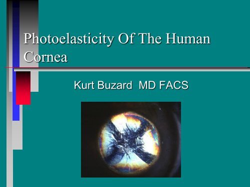
<strong>Photoelasticity</strong> <strong>Of</strong> <strong>The</strong> <strong>Human</strong><strong>Cornea</strong>Kurt <strong>Buzard</strong> MD FACS
• Photography:• Scott Hunt• Machine Tooling:• Craig Cerminara
Morris Klatskin PE• 1945-Adapted Retiniscope WithPolarized Filters To Find Sliver <strong>Of</strong> SteelIn Own Eye• 1946-Raytheon-Manhattan ProjectPolarizing Filters To Show Stress InPlastic Insulators• 1972-Rand Project To Detect GlaucomaOptically.....Unable To Correlate EffectTo Increased IOP
Polarizing Filters• Normal White Light Is Like A WaveVibrating In All Directions• Polarizing Filters Allow Vibration In OnlyOne Direction• If Polarized Light Is Observed With ASecond "Crossed" Polarizing Filter............ No Light Is Passed
Polarizing Filters
Birefringent Materials• Any Material Which Can Change <strong>The</strong>Polarization <strong>Of</strong> Light• Placed Between Crossed PolarizedFilters, Causes Bands <strong>Of</strong> Colored Light• Used In Pathology To Identify CertainBiologic Materials: Amyloid In Lattice<strong>Cornea</strong>l Dystrophy
Stressed Hard Plastic
<strong>Photoelasticity</strong>• Force Applied At A Point On A GlassPlate Generates A Series <strong>Of</strong>Photoelastic Stress Lines• Viewed Through Crossed PolarizingFilters• Internal Material Stress Can Be InferredFrom <strong>The</strong>se Pictures
<strong>Photoelasticity</strong>PhotoelasticStresLinesApliedForce
Non-Parallel Surfaces
IOL with Stress Defect
Experimental Setup• Cadaver Eye Was Bisected, UvealContents Were Eviscerated• Mounted On Plexiglass Tube Filled WithFluid• Polarized Light Directed Through<strong>Cornea</strong>• Observed Through Crossed PolarizedFilter
Experimental Setup
Experimental Setup
Light Microscopy• Low Power Light Microscopy ShowsFibrillar Structure <strong>Of</strong> <strong>Cornea</strong>• Unfortunately Little Additional Detail IsRevealed Concerning Collagen Fibrils• Question Exact Length <strong>Of</strong> IndividualCollagen Fibrils• Question Anchor Points of CollagenFibrils
<strong>Cornea</strong>l Structure
Electron Microscopy (TEM)• <strong>The</strong> Higher Power <strong>Of</strong> ElectronMicroscopy Shows More Details• Alternating Direction <strong>Of</strong> Collagen FibrilLayers• Questions Remain About Length AndAnchoring <strong>Of</strong> Collagen Fibrils
<strong>Cornea</strong>l Structure (TEM)FibrilsPerpendicularFibrilsParallel
Collagen Fibril Distribution• <strong>The</strong>ories <strong>Of</strong> Collagen Fibril DistributionUsually Assume Fibrils Run FromLimbus To Limbus• Little Evidence To Support <strong>The</strong>se<strong>The</strong>ories
Collagen Fibril Distribution<strong>The</strong>oriesSchachar, Black,HuangKeratorefraction1980Pinsky, Datye: Ref &<strong>Cornea</strong>l Surg8;192p164-172
Experimental Results• Unexpected Pattern Observed ThroughCrossed Polarized Filters• <strong>Cornea</strong>l Fibrils Appear To Be Arranged InPeripheral "Leaves" Rather Than EvenLayers• Suggests ThatCollagen Fibrils MayNot Extend FromLimbus To Limbus
Orientation <strong>Of</strong> Crossed Filters• <strong>The</strong> Pattern Observed Seems To Change InIntensity And Color By Rotating RelativePosition <strong>Of</strong> Crossed Polarizing Filters• <strong>Cornea</strong>l Collagen Distribution Seems MoreComplicated Than Originally Thought• Why Certain Layers<strong>Of</strong> Collagen FibrilsRespond To PolarizedLight Not Known
<strong>Cornea</strong>l Support Zones<strong>Cornea</strong>l Astigmatism Mosby-Yearbook 1992
<strong>Cornea</strong>l Support Zones• Polarized light examination of thecornea supports the concept ofperipheral support zones• Structural differences separate thesupport zones and these differenceshave clinical correlation
Arcuate Keratotomy• Enhanced Visualization <strong>Of</strong> Incisions• No Basic Change In Color Pattern
Arcuate Incisions - Coupling• Arcuate incisions are performed with anoptical zone of 7 mm ... In the peripheralsupport zone• T-cuts performed between 5-6 mm OZ,in the intermediate support zone, couplefairly accurately to maintain sphericalequivalent• Coupling of arcuate incisions is muchmore erratic, perhaps related tostructural factors
Mini-RK• Lindstrom Mini-RK has minimizedpenetration intoperipheral supportzone• Slightly less effect• Perhaps betterlong term stabilityOZCenteredOnVisual AxisLimbus
Mini-RKOZ3.5m4-Cut RKAvg5CadaverEyesCorrection Percentage (D)9 1008 .1 181007 80 7 3 .75 .9 8656043 9 .83 .2 3 4032 2010 02 mm 3 mm Limbus 2 mm 3 mm LimbLength <strong>Of</strong> RK Length Incisi OSabates, Friedlander, <strong>Buzard</strong>/ SubmitedForPublication
<strong>Cornea</strong>l Pressure• Preexisting Pattern Seen With CrossedPolarizing Filters Disrupted By SimplePressure Applied With Forceps
<strong>Cornea</strong>l Suture• Disruption <strong>Of</strong> Natural Pattern Seen WithCrossed Filters• Stress Lines Can Be Seen Both Under <strong>The</strong>Suture and At <strong>The</strong> Ends <strong>Of</strong> <strong>The</strong> Suture• This Effect Can ProvideVisual Feedback WithRegards To SutureTension
Probe In <strong>Cornea</strong>l Incision• <strong>Cornea</strong>l Stress Can Be Induced With AHook In <strong>Cornea</strong>l Incision• Note "Wake" <strong>Of</strong> Induced <strong>Cornea</strong>l StressLines
Slit Lamp Adaptation• Adaptation <strong>Of</strong> Slit Lamp Can ProvideClinical Application <strong>Of</strong> CrossedPolarizing Filters• Filter Placed On Slit Beam And CrossedFilter Placed On Optics <strong>Of</strong> Slit Lamp• Polarized Light Is Reflected From IrisThrough <strong>Cornea</strong>
Slit-Lamp AdaptationPolarizingFilterCrosedPolarizingFilter
Basic Pattern• Much Different Color Pattern With Slit LampAdaptation• Typically 3-4 Peripheral Colored BandsSeparated Into 4 Quadrants• Perhaps Bands Related To Rectus Muscles• Colored Bands May Be Related To ChangesIn <strong>Cornea</strong>l Thickness• Similar Patterns Seen InPre-stressed SpectacleLenses
Stromal Fine Structure• Polarizing Filters Eliminate SurfaceGlare• Internal Stromal Structure BecomesMore Visible...<strong>Cornea</strong>l Nerves,Keratitis,Etc.• Lens InternalStructure AlsoMore Apparent
Tight <strong>Cornea</strong>l Suture• Disruption <strong>Of</strong> Color Banding Pattern• Similar Stress Lines As Seen InExperimental Setup• May Provide A Real-Time Method <strong>Of</strong>Assessing Suture Tension In OperatingRoom
Circular <strong>Cornea</strong>l Suture• Good Visualization <strong>Of</strong> Suture• No Disruption <strong>Of</strong> Basic Color Pattern• Note Disruption <strong>Of</strong> Pattern At Location<strong>Of</strong> Suture Knot
Radial Keratotomy• No Change In Basic Color Pattern• Incisions Become Much More Apparent• Improved Determination <strong>Of</strong> IncisionDepth• Eye-Bank Screening For RK
Keratoconus
Keratoconus
Keratoconus
Summary• <strong>Cornea</strong>l Stromal Structure MoreComplex Than Previously <strong>The</strong>orized• Improved Visualization <strong>Of</strong> <strong>Cornea</strong>lIncisions At Slit Lamp...ImprovedDetermination <strong>Of</strong> Incision Depth• Eye-Bank Screening For RK
Summary• Suture Tension Is Seen By Distortion <strong>Of</strong>Basic Pattern And Colored Stress Lines• Possibly Useful As An Adjunct To<strong>Cornea</strong>l Topography• Keratoconus Shows Distortion <strong>Of</strong> BasicPattern• Future Work Will Focus On EnhancingEffect With Different Combinations <strong>Of</strong>Filters